After the engine was restored to working order, the motorcycle started, but the battery did not charge. In connection with this, the generator and relay regulator were completely checked. In the end, the reason was in the relay regulator. Moreover, I changed the relay-regulator to a new one. Or rather new in the sense that it had not been used before, but its year of manufacture was old, which was the reason it did not work. And now in more detail and in order about the process of checking the generator and relay regulator.
Replacing a relay regulator on a motorcycle
Sooner or later, almost all owners of Ural or Dnepr motorcycles are faced with a battery charge problem.
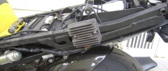
The standard relay-regulator type PP 330 eventually stops working correctly and needs to be cleaned or adjusted. Not every motorbike owner can competently perform these operations. Replacing with a new one is an option, but the cost of a new PP 330 is often quite high. Getting out of the situation, however, is quite simple. After all, you can install in the regular place of the PP 330 an electronic voltage regulator of type 121.3702 for 12V from a VAZ car, which is sold in any auto store, and its cost is several times lower than the PP 330. But for this you will have to work quite a bit with the wires. The electronic voltage regulator is installed in the standard place of the PP 330 with virtually no modifications. During the replacement process, it is necessary to additionally drill one hole in the mounting area of the regulator relay. You also need to replace the screw terminals on the wires that go to the PP with female connectors.
We connect the wire that went to the terminal (VZ) on the PP 330 (upper terminal) to the connector (15) of the electronic relay. We connect the wire that went to terminal (Ш) (lower right terminal for PP 330) to connector (67). We screw the ground wire to the metal base of the electronic relay (31) through the screw securing the housing to the platform. Two wires remain unconnected: LC - control lamp (lower left terminal) and “change” (middle lower terminal). For “lazy” motorcyclists, the conversion process can be considered complete; you just need to insulate these two wires and leave them hanging in the air, screwing them to the frame with something so that they don’t dangle. In this case, the battery will charge, but the alternator warning lamp on your motorcycle will not light up.
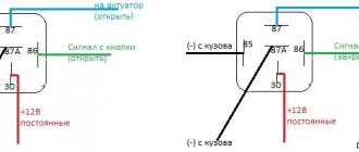
For those owners who are not satisfied with “half measures”, we continue the process. Together with the electronic relay regulator, you need to purchase a small relay of type RS 702 or (75.3777) with normally closed contacts from the auto shop. The RS 702 is remarkable in that when voltage is applied to the relay winding. the relay contacts open. This additional relay can be installed on one of the screws securing the electronic relay-regulator.
We connect the relay type RS 702 as follows. We connect the wire that went to the terminal (change) of PP 330 to connector (86). We connect the wire that went to the terminal (LC) to the connector (87). We dealt with the wires hanging in the air. We connect connector (85) to ground with a separate wire. We connect connector 30/51 to the wire that goes to connector (15) of the electronic relay, which is also positive from the ignition switch.
Relay-regulator PP-330, troubleshooting
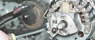
After I determined that the generator was working. I started searching for the faulty relay regulator. To understand the principle of its operation, a little theory.
I will not describe in detail the operation of the relay regulator; I will describe the problem that I fixed. This problem was in two relay regulators, and the reason for it was that due to a long time of inactivity of the contacts, the carbon contacts of the R.N. coil. (in the diagram above) oxidized and did not pass current.
During normal operation of all equipment, the process is as follows. When you turn the key S1: “+” from the battery is supplied to the ignition coil and to the V3 contact of the relay regulator. In the relay, power from the VZ contact passes through the RN coil. and to contact “Ш” of the generator, a rotor winding is connected to it. Thus the armature is excited by the battery. When the engine speed increases, at contact "
» alternating voltage appears, the R.KL relay is activated, and the control lamp turns off.
Also, as the speed increases, the voltage at the “+” contact of the generator also increases. It is connected to the R.N. relay, when a certain voltage threshold is reached, the relay is activated and the power goes not directly through the relay coil with a small resistance, but through the load resistances, thereby reducing the voltage on the rotor. By reducing the voltage level on the rotor, the current strength decreases, and, accordingly, the magnetic force of the rotor decreases. Which leads to a decrease in voltage at the outputs of the stator windings. When the voltage in the relay R.N. decreases The relay holding current drops, thereby the R.N. contacts. return to their original state and the process repeats.
Checking the motorcycle's charging.
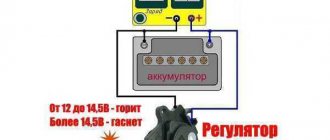
- We take a tester and set it to measure constant voltage (if there is a gradation of measurements, set it to 20 V). We measure the battery with the motorcycle not running. A fully charged battery is 12.8 - 12.9 volts (if less, it is advisable to charge the battery so that further measurements are correct, and also check the battery - you can read how to do this in the article: How to check the battery .)
- If the battery is serviceable and infected, we proceed to check the charging of the motorcycle. We measure the voltage on the battery with a tester, with the motorcycle running (idling, without consumers turned on: lights, heated handles, etc.), the voltage should be 13-15 volts. If the motorcycle charging test does not meet the criteria, move on.
- We turn on only “natural consumers” (lights), the voltage should be at least 12.8 volts (ideally, about 13.5 volts). If less, something is wrong.
- We turn on all consumers (additional equipment), if the voltage drops below 12.8 volts, try raising the idle speed to 1000 - 1100, the voltage should be at least 12.8 volts. If it is smaller, the generator does not pull all consumers (additional equipment) and may burn out.
- We give the gas 3000 - 4000 revolutions, the voltage should rise to 13 - 15 volts with all consumers turned on. On some motorcycles, the voltage rises to a maximum at 3500 -4000 rpm, and at higher rpm it drops, but not more than 13 volts (this is due to increased load at high rpm: the injectors begin to consume more power (they are open almost all the time), this is normal ). If less, something is wrong.
Relay regulator from VAZ together with relay RS-702
Yes, we should. There is still a lot more to drill, saw, cook, digest. It’s funny sometimes to see how some people think that you can go to the store, buy something shiny new, screw it on the side of a motorcycle and it will immediately take off like a rocket. He won't trample. More precisely, it will trample, but you need to invest sooo much effort, time, nerves, money and generally devote half your life to this. And then in the end it turns out that, for example, Japanese or all sorts of American motorcycles are better. . It’s especially funny to see how poor urinal wankers “make” some old grandfather’s old village matatsykla, diligently polishing something there until it shines. In the garage, among the piles of rubbish and other garden and manure crap, it really looks like such a worthless clunker. Sometimes it even starts and rattles violently. But as soon as he is at a party and placed next to, for example, some simple Viraga or something else, you can immediately see what kind of shit it really is. That's why I never intended to make Khorley-Davitsan out of the Dnieper. From the Dnieper with a stroller you can only make a good Dnieper with a stroller. You never make candy out of shit. Regardless of any shiny packaging, the contents will taste the same. So if you want normal carbs, buy Bingi for 30,000 rubles. If you don’t have that kind of money, fuck with the Ketaisk shit, drill holes, drink with a file, etc. . And by the way, setting up a relatively normal motorcycle on shitty carbs is much more difficult than non-German supercarbs. This is a business for real men who do not back down from difficulties. You have the right to cry, get angry, kick your tank in a frenzy and yell “Come on, f.... it's shit!!! This is no one's business and it is your own business. But if you completed your mission to the end and achieved results, you are a man. If your motorcycle doesn't work, is pushed into a corner and is littered with junk, you're a wuss. . Why am I writing this nonsense - apparently you are a newbie. So if the motorcycle is “a bad manufacturer, I tried everything, blew spark plugs, what could be wrong?” - Congratulations. You are on a difficult path of growing up and becoming a person. But nothing, it’s only the first 10 years that are hard. Then you’ll get used to it if you don’t push scrap metal into a ditch. So new carbs not working are just the beginning. Hang in there bro. . I myself drive on the Dnieper with K-301 carbs and a sidecar. It doesn't pull anything, it doesn't move at all. This is when compared, for example, with the Honda CBR 1000 RR Fireblade. I can compare. BUT! Starts up in any frost, rushes like a tank through the mud, carries 5 shit-drunk homies, drags at night through the forest in the rain in waist-deep mud on a rope the second dead Ural, on which there are 5 more of the same drunks, carrying potatoes, manure, bricks , cement, refrigerators, televisions, boards, logs, pipes, etc. At the same time, it does not consume gasoline. No Fire can do anything even close to that. . Again, this is what it’s all about - if you have a Ural, be quiet, behave more modestly and don’t try to make a rocket out of it. And get used to hard sex with a motorcycle. Start with the carbs. Then you get a taste for it - there will be a lot of other sexy things there. . On the abyss of the Dnieper and the Urals - Dnieper
If something is wrong.
- Disconnect the relay regulator (remove the connector). Let's take a tester.
- We set the tester to measure resistance. We check the resistance between ground (engine) and the generator wires (three wires, usually yellow). It shouldn't exist. If at least one has it, your motorcycle's alternator has burned out.
- We check the resistance between the generator wires, the resistance should be the same, about 1 - 3 ohms. If it is more or not the same, your motorcycle's alternator has burned out.
- We set the tester to measure alternating voltage. We start the motorcycle, measure the voltage between the generator wires, it should be more than 18 volts at idle, and more than 40 volts at 3000 - 4000 rpm. If there is no or different voltage, your motorcycle's alternator has burned out.
- If the check in points 2, 3 and 4 went well, most likely your motorcycle has a faulty Relay - Regulator or, which also happens, a wiring fault (clean all terminals, check the integrity of the wires, connections to ground). If your motorcycle's generator burns out, this is the place for you: Rewinding the generator with your own hands.
Our service will help you check the charging of your motorcycle.
Check the integrity of wires and connections.
They will eliminate all problems associated with charging the motorcycle.
If the motorcycle is not sufficiently charged, the following may fail: battery, relay - regulator, generator.
Generator G-11A of the Ural motorcycle.
Checking and adjusting the G-11A generator of the Ural motorcycle can be done in different ways. Serviceability is monitored by a warning light, and if for some reason it is missing or burnt out, then you need to remove one of the wires from the battery terminal at medium engine speeds. If the engine continues to run, then the generator is working.
The generator can also be checked by connecting one end of the wire to a portable lamp to ground, and the other to terminal I of the relay-regulator (in this case, the wires must be disconnected from terminals Ш and И). Then give the engine medium speed, and if the portable lamp lights up, then the generator is working.
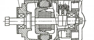
Generator G-424 motorcycle Ural
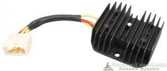
Electric generator G-424 is a three-phase machine, with electromagnetic excitation. Generates alternating current. A VGB-2A rectifier is installed, the function of which is to convert the current into direct current, necessary for the electrical consumers of the motorcycle. For normal operation of an electric machine, a relay-regulator PP-330 is required. The work consists of connecting a generator or battery to the mains at a certain moment.
A distinctive feature of the G-424 generator is its inability to operate with a discharged battery. To start the engine and increase to 2400 rpm, the motorcycle runs on a battery. Only after this threshold is exceeded does the electric generator operate in self-excitation mode.
Generator circuit G-424: 1 - cover; 2 — oil seal; 3 - rotor; 4 - stator winding; 5 - terminal block; 6 — back cover; 7 — shield assembly; 8 - rectifier block; 9 - fan; 10 — protective casing; 11 - bearing.
Technical characteristics of G-424
1 – Voltage – 14 volts. 2 – Power – 150 watts. 3 – Full output current – 11 amperes. 4 – Total weight – 3.8 kg. 5 – The direction of rotation of the armature is right. 6 – The polarity of the motorcycle body is negative (minus). 7 – Specific power – 42 W/kg. 8 – Service life – 40,000 km.
The G-424 rotor is driven by a gear mounted on the engine camshaft. The gear ratio between the shafts is 1.33. The cantilever mounting on the crankcase is made with two studs
Adjusting the noise of G-424 gears
Loosen the nuts of the mounting studs and start the engine, turning the generator in one direction or another. We achieve the lowest gear noise. Having established the required gap, tighten the nuts. This is how the gearing of the drive gears is adjusted.
Incorrectly set drive gear engagement leads to overheating, premature gear wear and shaft failure.
content .. 60 61 62 ..CHAPTER VI.
ELECTRICAL EQUIPMENT FOR MOTORCYCLES “URAL”, “DNEPR”
The electrical equipment of a motorcycle consists of sources and consumers of electrical energy, auxiliary devices and an electrical network. It provides ignition of the working mixture in the engine cylinders, lighting, sound and light signaling.
The electrical network, which consists of low voltage wires, is made using a single-wire system, i.e. From electrical energy sources, users are supplied with one wire from the positive poles of the battery and generator; the functions of the second wire are performed by the frame, as well as the metal parts of the motorcycle.
To control the operation of the generator and relay regulator, a red PD20-E lamp is used. Extinguishing the lamp after starting the engine indicates the serviceability of the generator and relay regulator.
Motorcycles “Dnepr” and “Ural” are equipped with lamps for monitoring emergency oil pressure, neutral, turns, and high beams. The G-414 generator and the ZMT12 battery are used as a current source on motorcycle models with a six-volt voltage "Dnepr" and "Ural", on models with a 12-volt voltage a G-424 generator and two
rechargeable batteries ZMT-6 or one 6MTS-
Rice. 6.1. Electrical diagram of the K-650 "Dnepr" motorcycle: 1 - high and low beam lamp A6-32+32; 2 - key; 3 - fuse 15 A; 4 — indicator lamp PD-20; 5 - warning lamp for emergency oil pressure sensor A6-1; 6 - central switch; 7 - emergency oil pressure sensor; 8 — candle tip; 9 — spark plug; 10 — ignition coil B201; 11 — front lamp of stroller A6-2; 12 — front light of the PF-200 stroller; 13 — sound signal S-37A; 14 — wire connector; 15 — brake light lamp A6-15; 16 - rear parking light lamp A6-3; 17 — rear marker light of the stroller; 18 — rear light FP-230; 19 — brake signal switch; 20 — relay-regulator PP302; 21 - generator G-414; 22 — breaker-distributor PM302; 23 — battery ZMT-12; 24 — sound signal button; 25 — ignition timing lever; 26 — speedometer illumination lamp A6-2; 27 — control lamp for generator operation A6-0.25; 28 — switch for high beam and parking lights; 29 — parking light lamp A6-2
Rice. 6.2. Electrical diagram of the K-650 "Dnepr" motorcycle with a two-terminal ignition coil: 1 - high and low beam lamp A6-32+32; 2 - key; 3 - fuse 15 A; 4 - indicator lamp PD-20; 5 - warning lamp for emergency oil pressure sensor A6-1; 6 - central switch; 7 — emergency oil pressure sensor; 8 — candle tip; 9 — spark plug; 10 — breaker-distributor PM05; 11 — front lamp of stroller A6-2; 12 — front light of the PF-200 stroller; 13 — sound signal S-37 A; 14 - wire connector; 15 — brake light lamp A6-15; 16- rear parking light lamp A6-3; 17 — rear marker light of the stroller; 18 — rear light FP-230; 19 — brake signal switch; 20 — relay-regulator PP302; 21 — generator G-414; 22 — ignition coil B2-B; 23 - rechargeable battery ZMT-12; 24 — sound signal button; 25 — switch for high and low beam; 26 — speedometer illumination lamp A6-2; 27 - control lamp for generator operation A6-0.25; 28 — parking light lamp A6-2
Rice. 6.3. Electrical diagram of the MT9 motorcycle: 1 - high and low beam lamp A6-32+32; 2 - lamp A6-15; 3 — direction indicator light UP-223; 4 — ignition key; 5 - fuse 15 A; 6 — indicator lamp PD-20; 7 — warning lamp for emergency oil pressure sensor A6-1; 8 — emergency oil pressure sensor MM106A; 9 - central switch; 10 — wire connector; 11 — turn switch P25; 12 — lamp A6-3; 13 — front light of the PF-232 stroller; 14-candle tip; 15 — spark plug A8U; 16-breaker-distributor PM05; 17-ignition coil B2-B; 18 — sound signal S-37A; 19 — rear light of the FP219 stroller; 20 — lamp A6-21 +3; 21 — brake signal switch VK854; 22 — rear light of the FP-217 motorcycle; 23 — relay-regulator PP-302; 24 — direct current generator G-414; 25 — battery ZMT-12; 26 — speedometer illumination lamp A6-2; 27 — sound signal button; 28 — RS419 turn signal interrupter relay; 29 — ignition timing adjustment lever; 30 — neutral sensor (contact plug); 31 — light switch cable; 32 — indicator lamp PD-20G; 33 — indicator lamp for the neutral position of the gear shift lever A6-1; 34 — light switch P45; 35 - control lamp for turning on the generator A6-0.25; 36 - parking light lamp A6-2; 37 — headlight FG-116; wire colors: I - black; II - white; III - red; IV - green; V - brown; VI - yellow; VII - blue; VIII - purple; IX - gray
Rice. 6.4. Electrical diagram of an MT9 motorcycle with a two-terminal ignition coil: 1 - high and low beam lamp A6-32+32; 2 — lamp A6-15; 3-turn signal lamp UP-223; 4 - ignition key; 5 - fuse 15 A; 6 — indicator lamp PD-20; 7 — warning lamp for emergency oil pressure sensor A6-1; 8 — emergency oil pressure sensor MM106A; 9 - central switch; 10 — wire connector; 11 — turn switch P201; 12-lampA6-3; 13 — front light of the PF-232 stroller; 14-candle tip; 15 — spark plug A8U; 16-ignition coil B201 A; 17 — breaker PM302; 18-sound signal S-37 A; 19 — rear light of the FP219 stroller; 20 — lamp A6-21+3; 21 — brake signal switch VK854; 22 — rear light of the FP-217 motorcycle; 23 — relay-regulator PP-302; 24 — direct current generator G-414; 25 — battery ZMT-12; 26 — speedometer illumination lamp A6-2; 27 — sound signal button; 28 — RS419 turn signal interrupter relay; 29 — light switch P25; 30 — neutral sensor (contact plug); 31 — indicator lamp PD-20G; 32 indicator lamp for the neutral position of the gear shift lever A6-1; 33 — control lamp for turning on the generator; 34 — parking light lamp A6-2; 35 — headlight FG-116; wire colors: I - black; II - white; III - red; IV - green; V - brown; VI - yellow; VII - blue; VIII - purple; IX - gray
Rice. 6.5. Electrical diagram of the K-750M motorcycle: 1 - high and low beam lamp; 2 — ignition key; 3 - fuse; 4 - headlight; 5 - central switch; 6 — wire — “ground”; 7 - high voltage wire; 8 — spark plugs; 9 - high voltage wire; 10 — ignition coil; 11 — front light of the stroller; 12 — sound signal; 13 - wire for the front light of the stroller; 14 — rear light of the stroller; 15 — rear lamp of a motorcycle; 16 - brake light sensor; 17 - relay-regulator; 18 - DC generator; 19 — battery; 20 — low voltage wiring harness; 21 - battery wire - ground; 22 - breaker; 23 - distributor; 24 - high voltage wire; 25 — ignition coil wire; 26 — signal button; 27 - signal wire; 28 — ignition timing adjustment lever; 29 — cable for switching parking and high beams; 30 — switch for parking and high beams; 31 — control lamp; 32 — parking light lamp; 33 — speedometer illumination lamp; 34 — wire connector; 35 — wire for stroller lights; 36 — wire from the sensor to the brake light lamps; 37 - wire from the connector to the license plate lamp
Rice. 6.6. Electrical diagram of the motorcycle "Dnepr-11": 1 - direction indicator 162 3726; 2 — lamp A12-21-3.3; 3 — front lamp PF232V of the side trailer; 4 — lamp A 12-21+6; 5 — switch 171 3709; 6 — contact plug; 7 - emergency oil pressure sensor MM 126; 8 — switch VK854B; 9 - wire “switch 46 3710 - ground” voltage regulator 33 3702; 10 — rear side trailer lamp FP219V; 11- PD20D lamp of the direction indicator warning lamp; 12 — PD20D lamp for the neutral sensor warning lamp; 13 - flashlight PD20E warning lamp for emergency oil pressure, 14 - turn signal switch RS427; 15 — PRIM fuse block; 16 - voltage regulator 33 3702; 17 - battery negative wire - switch 46 3710; 18 — direction indicator 163 3726; 19 — battery 6MTS9; 20 — instrument panel; 21 — generator G424; 22 — noise suppression tip A14; 23 - PP cartridge 1-200 lamps; 24 - rear lamp 171 3716; 25 — lamp A12-5; 26 - headlight FG137B; 27 - lamp A12-45+40; 28 lamp A12-4; 29 — flashlight PD20M high beam warning lamp; 30 — PD20E lamp for the generator operation warning lamp; 31 — ignition switch 141 3704; 32 — switch 181 3709; 33 — sound signal S205B; 34 — wire “ignition coil breaker; 35 — ignition coil B204; 36 - spark plug A14B; 37 — breaker PM302A; 38 - high voltage wire; 39 — speedometer; 40 — handbrake brake light switch 13 3720; 41 — lamp A12-8; 42 - switch 46 3710; 43 - lamp A12-1; 44 — fuse PR 9B-210; wire colors: g - blue; g - yellow; z - green; k - red; kch - brown; o - orange; c - gray; f - purple; h - black
Rice. 6.7. Electrical diagram of motorcycles "Ural" M62, M63, M66: I - direction indicator switch P-201; 2 - right direction indicators with A6-15 lamps on a single motorcycle; 3 — connecting block; 4 - headlight lamp A6-32+32; 5 — parking light lamp for headlight A6-2; 6 — relay-interrupter of direction indicators; 7 - left direction indicators with lamps from A6-15; 8 — sound signal S-37A; 9 — light switch with sound signal button P-200; 10 — speedometer scale illumination lamp A6-2; II - fuses 15A; 12-centre switch; 13 — generator G-414; 14 — control lamp for generator operation A6-0.25; 15 — relay-regulator PP-302A; 16 — ignition coil B201; 17 — breaker PM302; 18 — right direction indicators with lamps A6-15 (on the sidecar); 19 — front parking light on a sidecar with lamp A6-2; 20 — brake light lamps A6-15; 21 — rear marker lamps A6-22; 22 — battery ZMT-6; 23 — brake light switch; 24 - warning lamp for emergency oil pressure A6-2; 25 - oil pressure sensor (only Ural M66 are equipped with direction indicators).
Rice. 6.8. Electrical diagram of the Ural motorcycles M67 and M67-36: 1 - right turn indicators on a single motorcycle with A12-21-3 lamps; 2 — headlight lamp A12-45+40; 3 front parking light lamp A12-4; 4 — left direction indicators with lamps A12-21-3; 5 — direction indicator switch P201; 6 — relay-interrupter of direction indicators; 7 — indicator lamp A12-1; 8 — speedometer scale illumination lamp A12-1; 9 — fuse block; 10 — control lamp for generator operation A12-1; 11 — ignition switch VK857; 12 — light switch with sound signal button P200; 13 — sound signal S205B; 14 — right direction indicators with lamps A12-21-3; 15 — front side light with lamp A12-5; 16 — relay-regulator PP-330; 17 — generator G-424; 18 — ignition coil B204; 19 — spark plugs A14B; 20 — breaker PM302A; 21 — tail light and brake light lamp A12-21+5; 22 — brake light lamp A12-21-3; 23 — brake light switch; 24 -6MTS-9 or two ZMT-6 batteries; 26 - ground switch
Rice. 6.9. Electrical diagram of the Ural motorcycles IMZ-3.103-10, IMZ-8.103-30, IM3-8.103-40 and IMZ-8.123: 1 - emergency ignition switch; 2 - day-night switch; 3 — plug connector blocks; 4 — handbrake brake light switch; 5 — relay-interrupter of direction indicators; 6 — fuse block; 7 neutral indicator lamp in the A-12-1 gearbox (green); 8 — indicator lamp A12-1 (orange); 9 — lamps A12-1 for illuminating the speedometer scale; 10-headlight lamp A12-45+40; 11 — side (parking) light lamp in headlight A12-4; 12 — left direction indicators with lamps A12-21; 13 — high beam indicator lamp A12-1 (blue); 14 — control lamp for generator operation A12-1 (red); 15 - ignition switch; 16 — direction indicator switch; 17 — light switch; 18 — right direction indicators (on a wheelchair) with lamps A12-21; 19 — side (parking) light lamp on the front sidecar A12-5; 20 — two-filament lamp for rear parking light and brake light A12-21+5; 21 — relay-regulator PP-330; 22 — foot brake brake light switch; 23 — ground switch; 24 — neutral control lamp switch; 25 — sound signal S-304; 26 — ignition coil B204; 27 — generator G-424 with rectifier; 28 — breaker PM302A; 29 — sound signal button; 30 — lamp AI2-21 brake light; 31 — lamp A12-5 rear marker (parking) light; 32 — 6MTS-9 battery (or two ZMT-6 batteries); 33 — switch of the contactless electronic ignition system (BESZ); 34 — BESZ sensor; 35 - electronic voltage regulator 33 3702; 36 — right direction indicators on a single motorcycle with A12-21 lamps
content .. 60 61 62 ..
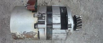
Generator G-414 of the Ural motorcycle.
The first production of motorcycles used six-volt electrical equipment. Accordingly, the generator generated direct current at the required voltage. It is installed in a special hole in the engine crankcase and secured with a tightening tape. Adjusting the gear engagement as on the G-11A is described above.
Generator circuit G-414:
1 – anchor; 2 – winding; 3 – bandage; 4 – collector; 5 – cover; 6 – rear bearing; 7 – cover; 8 – output; 9 – shields; 10 – coil; 11 – body; 12 – front cover; 13 – protective washer; 14 – front bearing; 15 – oil seal; 16 – key; 17 – castle nut.
GENERATOR 700 W | OPPOZIT.RU | motorcycles Ural, Dnepr, BMW
The resistance between the windings must be the same. The engine is started and the rotor rotates in the stator winding, voltage is supplied to the excitation winding through the PP and the generator is excited.
As practice has shown, pieces of nails driven into holes cope with the task. If the voltage is outside the technical specifications, replace the regulator. In particular, automatic ignition timing was introduced, since the motorcycle received a new power unit, and the old manual control of the timing advance did not meet the technical requirements. The voltmeter reading is noted and, by bending the shank in the voltage relay, the spring tension is increased, and with it the generator voltage by 0.4 V. An additional rectifier arm is also introduced into the electrical circuit. During this period, you can slightly increase the generator voltage.
On a URAL car there is a voltage regulator. If the voltage is outside the technical specifications, replace the regulator. Adjust the position of the front wedge stops 9 on the closed lid 6 of the container 10 after installing the batteries 1 and the upper clamps into the container. If they come out of the special sockets, the phase leads may break off during generator operation.
Motorcycle relay regulator
Motorcycle equipment is equipped with a large number of mechanisms that must work efficiently and smoothly every day during the motorcycle season. The operation of all systems and components of motorcycle equipment must be regulated so that sooner or later the motorcycle does not fail and does not turn into a pile of metal. For this, there is a certain mechanism called a relay regulator. They are used to ensure that the voltage for the movement of the motorcycle is supplied to a certain level.
How does a relay regulator work for a bike?
Normally, the voltage supplied to the on-board circuit of any motorcycle device should not exceed twelve volts. However, the generator is capable of producing a higher voltage level. Typically it ranges from eight to forty-five volts. If such voltage is regularly applied, all motorcycle electronics may fail. The motorcycle will turn into a pile of metal. It is to protect against power outages that a motorcycle relay regulator is installed on motorcycle equipment.
Relay regulators are installed on all imported motorcycle vehicles. The role of the regulator relay is colossal. Thanks to it, you can avoid expensive motorcycle repairs. In addition, all systems are guaranteed to work like a well-oiled mechanism and will not fail for a long time due to failures in the voltage supply to the on-board networks of the motorcycle.
Motorcycle Voltage Regulator Relay Diagram
What to do if the relay regulator is broken
Sometimes a situation occurs when the relay regulator becomes faulty. In this case, there is no need to panic. It is very important to take certain measures to prevent all motorcycle systems from failing.
First, you urgently need to disconnect this device from the generator and from the battery so that they do not fail. The voltage will be supplied alternately.
The main thing is to pay attention to ensure that the generator does not fail. In this case, the voltage will be supplied from the battery, where there is a possibility that it will begin to boil away and increase in size. The result will be an explosive situation.
The motorcycle regulator relay diagram shows its structure. Thanks to this, you can figure out how to repair it and connect it.
How to check the relay?
In general it was like this. I was getting ready to start my trike, which had been sitting outside all winter. After charging the battery, cleaning the contacts and replacing some substance in the gas tank with gasoline, I finally revived it. And since the ignition key was lost and the lock itself was completely broken, I could not turn off the ignition. This means the engine is working, but I don’t have the brains to take off the candle holder to turn it off (there is no engine stop). So, instead of disconnecting the positive wire going to the coil, I short it to ground. The engine died down and, in general, all signs of life along with it. I looked at the fuses, one was burned out, I replaced it, everything was still dead. To clarify, this means that the charging control lamp does not light up. Then I took a piece of wire and connected the plus directly to the coil. The lamp does not light, mind you. So I start it and the light comes on. I have a separate breaker for the generator, so I turn on the generator, the lamp starts blinking. I turn off the engine, the lamp goes out. So the main question! Which of the two relays burned out? The wiring works according to the scheme described in https://custom26.ucoz.ru/forum/5-127-1
nait9, the control light is in your hands. and check for the presence of a plus where it should be. With a multimeter in low-resistance circuits, there is little that can be adequately checked other than the integrity of the wires.
IMHO the relay-regulator burned out. When my control lamp relay burned out after a short circuit, the control lamp was constantly shining, despite the fact that the RR was regularly charging. If you buy a new RR, look for one with diagnostic LEDs. RRs are the size of a matchbox.
All is good! The topic can be closed. I decided to do as Vetal41rus advised. I checked the power supply to the lock using a test lamp. Not finding it there, I took a piece of wire and connected it directly from the plus of the generator to the lock. The lamp works, the engine starts, the gene snorts. Looks like the wire has burnt out. Remove the tank. I just filmed it again. Eh.
In what cases can you ride a motorcycle without a regulator relay?
It is not recommended to drive without a regulator relay. However, there are situations when it fails. It takes a lot of time to restore it. Therefore, many motorcyclists do not wait for repairs and risk going on trips without this device.
Experts are skeptical about such risky trips and recommend driving without a regulator relay if:
- the battery has an absolutely full charge level,
- The battery is in perfect working order,
- The relay regulator must be in the off state.