Checking the motorcycle's charging.
- We take a tester and set it to measure constant voltage (if there is a gradation of measurements, set it to 20 V). We measure the battery with the motorcycle not running. A fully charged battery is 12.8 - 12.9 volts (if less, it is advisable to charge the battery so that further measurements are correct, and also check the battery - you can read how to do this in the article: How to check the battery .)
- If the battery is serviceable and infected, we proceed to check the charging of the motorcycle. We measure the voltage on the battery with a tester, with the motorcycle running (idling, without consumers turned on: lights, heated handles, etc.), the voltage should be 13-15 volts. If the motorcycle charging test does not meet the criteria, move on.
- We turn on only “natural consumers” (lights), the voltage should be at least 12.8 volts (ideally, about 13.5 volts). If less, something is wrong.
- We turn on all consumers (additional equipment), if the voltage drops below 12.8 volts, try raising the idle speed to 1000 - 1100, the voltage should be at least 12.8 volts. If it is smaller, the generator does not pull all consumers (additional equipment) and may burn out.
- We give the gas 3000 - 4000 revolutions, the voltage should rise to 13 - 15 volts with all consumers turned on. On some motorcycles, the voltage rises to a maximum at 3500 -4000 rpm, and at higher rpm it drops, but not more than 13 volts (this is due to increased load at high rpm: the injectors begin to consume more power (they are open almost all the time), this is normal ). If less, something is wrong.
If something is wrong.
- Disconnect the relay regulator (remove the connector). Let's take a tester.
- We set the tester to measure resistance. We check the resistance between ground (engine) and the generator wires (three wires, usually yellow). It shouldn't exist. If at least one has it, your motorcycle's alternator has burned out.
- We check the resistance between the generator wires, the resistance should be the same, about 1 - 3 ohms. If it is more or not the same, your motorcycle's alternator has burned out.
- We set the tester to measure alternating voltage. We start the motorcycle, measure the voltage between the generator wires, it should be more than 18 volts at idle, and more than 40 volts at 3000 - 4000 rpm. If there is no or different voltage, your motorcycle's alternator has burned out.
- If the check in points 2, 3 and 4 went well, most likely your motorcycle has a faulty Relay - Regulator or, which also happens, a wiring fault (clean all terminals, check the integrity of the wires, connections to ground). If your motorcycle's generator burns out, this is the place for you: Rewinding the generator with your own hands.
Our service will help you check the charging of your motorcycle.
Check the integrity of wires and connections.
They will eliminate all problems associated with charging the motorcycle.
If the motorcycle is not sufficiently charged, the following may fail: battery, relay - regulator, generator.
Checking the relay regulator
The relay-regulator should be checked when the battery charge voltage is not within the permissible range (instructions for checking the battery charge voltage)
In the version with a split seat, the relay-regulator is located on the left under the rear facing plastic, which must be removed (instructions for removing the rear plastic for a model with a split seat).
Photos of the location of the relay regulator:
In the version with a one-piece seat, the relay-regulator is located on the right under the rear facing plastic:
Disconnect the connectors of the relay regulator (black 6-pin and white 3-pin connectors) and check them for oxides and poor contact. The location of the connectors is shown in the figure below:
Measure the voltage, resistance and short circuit at the connector side of the main wiring harness according to the table:
If all charging system components are normal
(all readings meet the requirements of the table above) and there is no loss of contact in the connectors themselves, the wires between the main wiring harness and the relay-regulator, but a problem with the charge is observed -
replace the relay-regulator
.
How to properly configure the ignition of Izh Planet 5
It is preferable to carry out and regulate the ignition of the Izh Planet using a special tool, which at one time was included in the factory kit of each individual model. But if you don’t have such a tool, you can use a regular caliper.
So, to set up the launch system on Izh Planet 5, you will need the following tools:
- a probe or light bulb operating on 12 volts with two wires;
- depth gauge (vernier caliper);
- special feelers for accurately measuring gaps.
To correctly install the Izh Planet ignition, you first need to remove the cover from the generator. Alternatively, for convenience, you can also unscrew the right cover on the crankcase.
Next, to adjust the ignition of Planet 5, you should perform the following steps one by one:
- turn the crankshaft clockwise until the breaker opens as much as possible;
- loosen the bolt a little while turning the eccentric;
- set the necessary gaps (0.4 - 0.6 mm);
- tighten the bolt again;
- turning the crankshaft clockwise again, set the piston to the TDC mark;
- turning the crankshaft in the opposite direction, place the piston at a distance of 3 - 3.5 mm to the TDC mark;
- loosen the bolts;
- set the beginning of contact opening;
- tighten the bolts again and turn on the Planet 5 ignition.
Checking the relay regulator for diode integrity
The relay regulator can be checked for the integrity of the diodes present in it, which can also indicate a malfunction.
A multimeter is required for this test.
In the mode of testing the integrity of semiconductor diodes, the multimeter generates a small test voltage and current, which is applied to the diode being tested. If the diode is working properly, then when you connect the red probe (plus) of the multimeter to the anode, and the black probe to the cathode, the display will show the value of the voltage drop at the pn junction of the diode. If the connection polarity is reversed (red probe - cathode, black probe - anode), the display will show one, since the diode conducts current only in one direction. [1]
The relay regulator has two connectors: a black 6-pin with 4 contacts, which connects to the motorcycle wiring, and a white 3-pin, which connects to the generator. Disconnect the relay-regulator connectors from the generator and motorcycle wiring.
Set the multimeter to diode test mode.
Check the readings between the contacts of the white chip: 1 — 2, 1 — 3, 2 — 3
.
The multimeter should show 1
(no current flowing).
Black probe (negative) of the multimeter
connect
the green wire (negative) to the contact of the black connector
and check the readings one by one with the three contacts of the white connector.
In all cases, the multimeter should show 1
(no current flowing).
Black probe (negative) of the multimeter
connect to the contact of
the red wire (positive) of the black connector
and check the readings one by one with the three contacts of the white connector.
In all cases, the multimeter should show values such as 519
.
How to check PP with a multimeter on a moped?
The relay regulator on a Chinese scooter is checked using a multimeter with a voltmeter function. For this purpose, a simple DT-830 (or equivalent) is usually used. It is better to carry out diagnostics and measurement of output voltage with the device removed.
Verification algorithm:
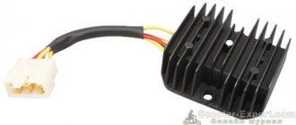
- You need to unscrew the fairing with the central phase and find on the frame a device with 4 wires: red, green, yellow and white.
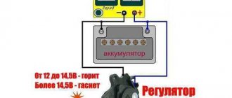
- Then start the scooter and check the voltage at idle: measure it between the green and red wires, setting the multimeter to the maximum value of 20 V.
- If the multimeter display shows a figure of 14.6-14.8 V, this is normal. For stabilizers on Chinese mopeds, this is the operating standard voltage. If at idle the multimeter shows a value of 15-16 V, this is a high voltage indicator. This indicates a malfunction of the relay regulator.
- Then you need to check the voltage supplied to the lighting lamps. An alternating voltage is supplied to the central low beam (high beam) lamp, so the multimeter should be switched to the alternating current measurement mode with a parameter of 20 V.
- Next, we measure the voltage between the green and yellow wires (green is the general electrical network of the moped). If the multimeter shows a network voltage of up to 12 V, then the electrical appliances are operating without additional load.
- If at idle this value is 16 V or higher, and with a sharp increase in engine speed it jumps to 25 V, the device does not stabilize the voltage and, therefore, does not work. With such readings, the device must be replaced with a new one.
Using a multimeter, they check the relay regulator on a Chinese scooter
On 4T scooters, the relay regulator is checked using a tester. Typically a mechanical tester is used for these purposes, although there are also electronic models.
In order to take a measurement, you need:
- switch the device to the “KiloOhm” mode and remove the regulator;
- then place the probes on the first pair of terminals (AB). The tester should show a value of no more than 18 kOhm;
- after that, we change the position of the probes on the terminals in the opposite direction (VA) and measure the voltage again - the arrow on the device should show 0;
- then we install the probes on the next pair of terminals (SD) and measure the readings on this pair;
- swap the probes (DS) and measure the indicator again;
- the remaining measurements have no contact and are not checked. The indicator when checking them should be zero.
In this way, regulators are tested on popular Japanese models with small engine volumes from brands such as Honda (Leard, Dio, Tact), Suzuki, Yamaha.
Checking the relay regulator and generator ZZR 400
Many owners of Japanese motorcycles experience various problems during their operation. I want to talk about one of them in more detail in my article.
Many have heard about it, and someone may have personally encountered the problem of charging the battery. Are the “Japanese” electrics really so unreliable? Which very often fails.
Let's look at this problem using the Kawasaki ZZ-R 400 motorcycle as an example.
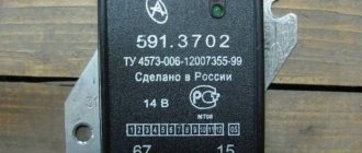
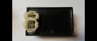
Often the main reason for the lack of battery charge is the failure of the relay regulator, the appearance is shown in the photo:
The RR has two main tasks: 1. To rectify the three-phase alternating current generated by the generator. voltage at 13.5-14.5 V.
Most often, RR is diagnosed with two “diagnoses”:
1. “WILL NOT CHARGE”
2. “NO LIMIT”
“WILL NOT CHARGE”
The problem is caused by the “burnout” of the rectifier bridge diodes. It is enough to simply mix up the “+”/“-” when connecting the battery. Exceeding the current consumption of the motorcycle's electrics leads to the same consequences. It could be a short circuit in the wiring. As a result of the RR failure, there may be consequences of “stupid tuning” of the motorcycle - installing additional “gadgets” in the form of different lights, additional headlights, increased power lamps, MUSIC. As you know, the generator has a maximum permissible power, exceeding which does not lead to anything good.
I would like to draw special attention to “lighting” a car, which is often practiced after “hibernation” and most often happens like this: they asked the motorist to “light” your horse, put a motorcycle next to it, put on wires and began to turn the motorcycle’s starter. As a result, after some time the motorcycle will start (if you’re lucky) and the motorcycle generator begins to charge both its dead battery and the dead car battery through the RR. The load is not small!
“NO LIMIT”
The RR must cut off excess generator energy from entering the motorcycle's on-board network; if this does not happen, the battery is recharged. It is obvious that the voltage regulation circuits in the PP circuit are destroyed. Everything produced by the generator passes into the on-board network of the motorcycle (and this is about 50 V and above, at maximum engine speed). Symptoms: the battery case gets hot, the temperature is more than 40 degrees. Motorcycle lamps burn too brightly and often burn out.
The result is boiling off of the electrolyte and rapid loss of capacity.
Another reason is caused by oxidation of the contacts in the PP block. As soon as one of the generator contacts to the RR has oxidized and partially lost its conductivity, a phase imbalance immediately occurs in the generator. Oxidized contact causes local overheating in the contact connections.
To avoid this, it is necessary to measure the voltage at the battery terminals at least once a month with the engine running, and monitor the condition of the generator and PP connectors.
But sometimes it happens that no one’s playful hands got into the electrics of the motorcycle, that is, all the electrics are “stock”, the motorcycle was not “lit.” Why did the RR burn down?
Let’s not forget that a motorcycle battery is essentially a “consumable” and its service life is two to three years.
It is also subject to wear and aging, loses capacity, and its own leakage current appears. During battery operation, sediment forms on the bottom of the battery. This sediment, upon contact with the plates, discharges the battery - self-discharge occurs. And this leads to constant recharging of the battery. An additional load is placed on the relay-regulator, which causes thermal overheating and destruction of the RR. I talked about possible problems and how to avoid them, now I’ll tell you how to check the functionality of the Relay-Regulator on your own, without contacting servicemen.
To check we need:
1. Sober head;
2. Basic knowledge of electrical engineering;
3. Lamp 12V/5W , preferably with a socket;
4. Six wires, at least 30-40 cm ;
5. Three charged batteries (you can get by with one, but this requires a power supply with a constant voltage of 12 to 24 V.
6. Multimeter DT-838 (any other is possible)
During engine operation, the RR should heat up within 40-50 degrees.
If the heat sink body has a higher temperature or is completely cold. These are signs that the RR is faulty.
First of all, we measure the voltage at the battery terminals, with the engine running, at idle U = 12.5-13.8 V.
At speeds of 4000-5000 thousand U = 14.2-14.5 V and with increasing speeds, the voltage SHOULD NOT INCREASE . Under no circumstances should you check the operation of the generator by disconnecting one terminal from the battery. There is a risk of burning the switch. This method only works on “soviet cycles”.
This is what the relay regulator looks like from the terminal block connector side:
The winding of a 3-phase generator is connected to the bottom row of contacts (three yellow wires)
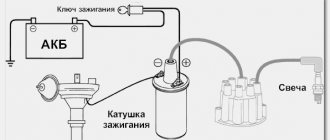
Installation and configuration instructions
In IZH Planet motorcycles, be it version 3, 4 or 5, the ignition installation in accordance with the diagram must be carried out using the device that came with the motorcycle. But since it is not so easy to find this device today, we will make do with improvised means. Non-contact ignition is configured by adjusting and setting the gap of the distributor contacts. An equally important nuance is the correct setting of the moment of sparking.
Diagram and designation of parts of the IZH distributor
If your IZH Planet 3 is equipped with a single-cylinder internal combustion engine with a G-36 M generator device, then in this case the procedure for setting the gap is carried out by turning the eccentric, marked in the diagram with the number 1. In this case, bolt 2 according to the diagram must be loosened, and the eccentric itself is turned or right or left. Before setting the BSZ on products from the IZHMASH plant, the crankshaft must be turned. It rotates until the moment of greatest divergence of contacts occurs. It is in this position that the ignition of the IZH Planet 5 is adjusted - you need to ensure that the maximum gap on the contacts is around 0.35-0.45 mm.
According to experts, the ignition system should be adjusted with the cylinder head removed. In this case, the piston itself must be located in a position where it does not reach the dead center; to find out what the clearance should be in this case, you need to use the instruction book. For example, in versions 3 this parameter should be 3.5-4 mm, in Planets 4 - from 3 to 3.5 mm, and in Sports versions - from 3.5 to 3.8 mm. It is in this position that the spark will appear. The adjustment procedure in this case is performed by turning the interrupter assembly, while the bolts marked in the diagram as number 10 must be loosened.
Assembly diagram for IL
Adjusting the ignition, in particular, setting the gaps between the contacts of the interrupter device, should be performed in the following order:
- First of all, the crankshaft is turned by the kick starter.
- One of the interrupting elements is set to the contact opening position. In this case, the bolt marked number 4 in the diagram must be loosened.
- Next, using the eccentric number 3, the gap is set; this figure should be from 0.4 to 0.6 mm. After this, the same actions are carried out with the second pair of contacts.
It should be noted that the entire procedure must be carried out with the candles unscrewed. When you place the dipstick in the corresponding hole for the spark plug in the right cylinder, you need to turn the crankshaft with the kick starter. You need to find the top dead center and having found it, you should make several marks on the dipstick - one of the marks should be placed at the level of the hole, and the other should be located slightly higher - about 2-3 mm. After this, the crankshaft must continue to be turned, this is done until the upper mark reaches the position in which the first mark at top dead center was set (video author - Garage in the USSR).
In this position, the elements of the interrupter assembly, which is located on the lower surface, will begin to open. It should be noted that the procedure for setting the contact opening is done by turning the base, but to do this you need to loosen the bolts numbered 2 and 7. And when you can make the adjustment correctly, these screws will need to be tightened. As for directly determining the moment of rupture, it can be detected thanks to a light bulb, which must be connected in advance to the body ground and the distributor terminal.
After the torque on the right cylinder has been set, the same procedure is performed in a similar way only on the left cylinder. In general, the situation is similar, only in this case it is not the lower, but the upper base that rotates, and in this case, bolts 1 and 7 should be loosened.
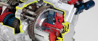
Generator G-424
To understand the principle of operation of the generator and relay regulator, a little theory.
Electric generator G-424 is a three-phase machine, with electromagnetic excitation. Generates alternating current. VGB-2A rectifier converts current into direct current. For normal operation of an electric machine, a relay-regulator PP-330 . The job is to regulate the voltage of the motorcycle's on-board network so that it does not exceed 14 volts.
The G-424 generator is not able to work with a discharged battery. To start the engine and increase to 2400 rpm, the motorcycle runs on a battery. Only after this threshold is exceeded does the electric generator operate in self-excitation mode.
Generator G-424 is PROHIBITED to be turned on without load!
Generator circuit G-424: 1 - cover; 2 — oil seal; 3 - rotor; 4 - stator winding; 5 - terminal block; 6 — back cover; 7 — shield assembly; 8 - rectifier block; 9 - fan; 10 — protective casing; 11 - bearing.
Troubleshooting the generator
The method for determining the malfunction was as follows (I tried several methods, since replacing the relay regulator did not help):
Indirect determination of generator performance
This method does not allow you to accurately determine the malfunction of the generator, but it can still be used to determine whether the generator is “dead,” or there is still hope and the cause of the malfunction lies elsewhere.
Disconnect the wire from terminal “Ш” on the generator. And we apply + from the battery to this terminal, bring the wrench to the generator body, it should be magnetic, not much, but it is noticeable. If it is magnetic, then the rotor winding is working properly. Turn it off.
We connect a 12 volt lamp to the “+” terminal on the generator, and the other end of the lamp to ground. And we connect “+” from the battery to the “Ш” terminal. And we turn the engine with the kickstarter, the light should light up. If this happens, then the generator is working.
In my case, the light was on, I changed the relay-regulator, but the battery still did not charge, and when the engine was running, the red battery charge control light did not go out.
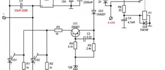
Relay-regulator PP-330, troubleshooting
After I determined that the generator was working. I started searching for the faulty relay regulator. To understand the principle of its operation, a little theory.
I will not describe in detail the operation of the relay regulator; I will describe the problem that I fixed. This problem was in two relay regulators, and the reason for it was that due to a long time of inactivity of the contacts, the carbon contacts of the R.N. coil. (in the diagram above) oxidized and did not pass current.
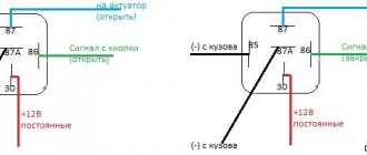
During normal operation of all equipment, the process is as follows. When you turn the key S1: “+” from the battery is supplied to the ignition coil and to the V3 contact of the relay regulator. In the relay, power from the VZ contact passes through the RN coil. and to contact “Ш” of the generator, a rotor winding is connected to it. Thus the armature is excited by the battery. When the engine speed increases, at contact "
» alternating voltage appears, the R.KL relay is activated, and the control lamp turns off.
Also, as the speed increases, the voltage at the “+” contact of the generator also increases. It is connected to the R.N. relay, when a certain voltage threshold is reached, the relay is activated and the power goes not directly through the relay coil with a small resistance, but through the load resistances, thereby reducing the voltage on the rotor. By reducing the voltage level on the rotor, the current strength decreases, and, accordingly, the magnetic force of the rotor decreases. Which leads to a decrease in voltage at the outputs of the stator windings. When the voltage in the relay R.N. decreases The relay holding current drops, thereby the R.N. contacts. return to their original state and the process repeats.
If the generator is spun up without a relay-regulator and a load, but the armature is excited, then as the speed increases, the EMF in the stator windings will increase, which theoretically can damage them (break through the insulation). Therefore, it is prohibited to turn on and spin up the G 424 generator without a load.
In my case, the carbon contacts of the R.N. relay were oxidized , thereby providing insufficient voltage to the rotor to excite it. The generator simply did not produce voltage.
Simply cleaning the contacts solved the problem .
Setting up contact ignition on Izh Jupiter - 5
Let's take a step-by-step look at how to set up contact ignition on this device:
- Align the piston of the desired cylinder: - insert a screwdriver into the cylinder - rotate the crankshaft while holding the screwdriver
- Take a ruler and place it next to the screwdriver.
- Rotate the crankshaft, holding the screwdriver down with your finger so that it is level. We find a dead point.
- Turn the crankshaft in the opposite direction (1.5-2 mm).
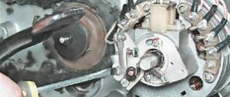
- A spark is generated when the cam opens, locate the two adjusting bolts.
- Take a light bulb with two contacts, connect one to ground, the other to the contact.
- Turn on the ignition switch.
- You need to find the moment when the light comes on (the moment it lights up, the start occurs), and when it goes out, the contact closes on the contrary.
- Turn off the ignition, do and adjust the same with the second cylinder