The most basic function of the generator is to charge the battery and power the electrical equipment of the engine.
Therefore, let’s take a closer look at
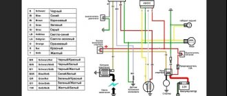
the generator circuit , how to connect it correctly, and also give some tips on how to check it yourself.
A generator is a mechanism that converts mechanical energy into electrical energy. The generator has a shaft on which a pulley is mounted, through which it receives rotation from the engine crankshaft.
- Accumulator battery
- Generator output "+"
- Ignition switch
- Generator health indicator lamp
- Noise suppression capacitor
- Positive power rectifier diodes
- Negative power rectifier diodes
- Generator "mass"
- Field winding diodes
- Windings of three stator phases
- Field winding power supply, reference voltage for voltage regulator
- Field winding (rotor)
- Voltage regulator
A car generator is used to power electrical consumers, such as the ignition system, on-board computer, car lighting, diagnostic system, and it is also possible to charge a car battery. The power of a passenger car generator is approximately 1 kW. Car generators are quite reliable in operation because they ensure uninterrupted operation of many devices in the car, and therefore the requirements for them are appropriate.
Generator device
The design of a car generator implies the presence of its own rectifier and control circuit. The generating part of the generator, using a stationary winding (stator), generates three-phase alternating current, which is then rectified by a series of six large diodes and the direct current charges the battery. Alternating current is induced by the rotating magnetic field of the winding (around the field winding or rotor). Next, the current is supplied to the electronic circuit through the brushes and slip rings.
Generator structure: 1.Nut. 2. Washer. 3.Pulley 4.Front cover. 5. Distance ring. 6.Rotor. 7.Stator. 8.Back cover. 9.Casing. 10. Gasket. 11.Protective sleeve. 12. Rectifier unit with capacitor. 13. Brush holder with voltage regulator.
The generator is located at the front of the car engine and is started using the crankshaft. The connection diagram and operating principle of a car generator are the same for any car. There are, of course, some differences, but they are usually associated with the quality of the manufactured product, the power and the layout of the components in the motor. All modern cars are equipped with alternating current generator sets, which include not only the generator itself, but also a voltage regulator. The regulator equally distributes the current in the excitation winding, and it is due to this that the power of the generator set itself fluctuates at a time when the voltage at the power output terminals remains unchanged.
New cars are most often equipped with an electronic unit on the voltage regulator, so the on-board computer can control the amount of load on the generator set. In turn, on hybrid cars the generator performs the work of the starter-generator; a similar circuit is used in other designs of the stop-start system.
The principle of operation of a car generator
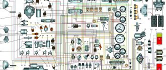
Connection diagram for the VAZ 2110-2115 generator
The alternator connection diagram includes the following components:
- Battery.
- Generator.
- Fuse block.
- Ignition.
- Dashboard.
- Rectifier block and additional diodes.
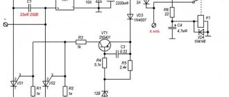
The principle of operation is quite simple: when you turn on the ignition, the plus goes through the ignition switch through the fuse box, the light bulb, the diode bridge and goes through the resistor to the minus. When the light on the dashboard lights up, then the plus goes to the generator (to the excitation winding), then during the process of starting the engine, the pulley begins to rotate, the armature also rotates, due to electromagnetic induction, electromotive force is generated and alternating current appears.
The most dangerous thing for the generator is the short circuit of the heat sink plates connected to the “ground” and the “+” terminal of the generator by metal objects accidentally falling between them or conductive bridges formed by contamination.
Next, the diode passes plus into the rectifier block through a sine wave into the left arm, and minus into the right arm. Additional diodes on the light bulb cut off the negatives and only positives are obtained, then it goes to the dashboard assembly, and the diode that is there allows only the negative to pass through, as a result the light goes out and the positive then goes through the resistor and goes to the negative.
The principle of operation of a car DC generator can be explained as follows: a small direct current begins to flow through the excitation winding, which is regulated by the control unit and is maintained by it at a level of slightly more than 14 V. Most generators in a car are capable of generating at least 45 amperes. The generator operates at 3000 rpm and above - if you look at the ratio of the size of the fan belts for the pulleys, it will be two or three to one in relation to the engine frequency.
To avoid this, the plates and other parts of the generator rectifier are partially or completely covered with an insulating layer. The heat sinks are combined into a monolithic design of the rectifier unit mainly by mounting plates made of insulating material, reinforced with connecting bars.
Next, let's look at the connection diagram for a car generator using the example of a VAZ-2107 car.
How to test a relay with a lamp
On many modern cars, the relay is combined with brushes. In this case, you can check the regulator using an incandescent lamp. The procedure will be as follows:
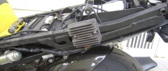
- To get to the part, you need to unscrew the mounting bolts and remove the terminals. The relay is located at the rear of the generator.
- To check, you need to prepare a 12V light bulb with a socket, wires, a voltmeter, and a power supply (no more than 20V).
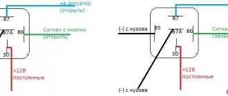
- Next you will need to assemble the following circuit.
- After connecting the light bulb, it should light up. At the same time, the voltage gradually increases. When it reaches 14.5V, the light should go out. If this happens later, it means the relay regulator is faulty.
When the voltage decreases, the lamp should light up again.
This test method can also be used for some models of regulators that are not combined with brushes.
Generator connection diagram for VAZ 2107
The VAZ 2107 charging scheme depends on what type of generator is used. To recharge the battery on cars such as VAZ-2107, VAZ-2104, VAZ-2105, which have a carburetor engine, you will need a G-222 type generator or its equivalent with a maximum output current of 55A. In turn, VAZ-2107 cars with an injection engine use a generator 5142.3771 or its prototype, which is called a high-energy generator, with a maximum output current of 80-90A. It is also possible to install more powerful generators with an output current of up to 100A. Absolutely all types of alternating current generators have built-in rectifier units and voltage regulators; they are usually made in the same housing with brushes or are removable and mounted on the housing itself.
The VAZ 2107 charging circuit has minor differences depending on the year of manufacture of the car. The most important difference is the presence or absence of a charge indicator lamp, which is located on the instrument panel, as well as the method of connecting it and the presence or absence of a voltmeter. Such circuits are mainly used on carburetor cars, while on cars with injection engines the circuit does not change, it is identical to those cars that were manufactured previously.
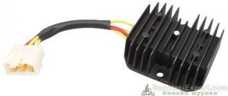
Generator set designations:
- “Plus” of the power rectifier: “+”, V, 30, V+, WAT.
- “Ground”: “-”, D-, 31, B-, M, E, GRD.
- Excitation winding output: Ш, 67, DF, F, EXC, E, FLD.
- Output for connection to the serviceability lamp: D, D+, 61, L, WL, IND.
- Phase output: ~, W, R, STA.
- Output of the stator winding zero point: 0, MP.
- Output of the voltage regulator for connecting it to the on-board network, usually to the “+” of the battery: B, 15, S.
- Voltage regulator output for powering it from the ignition switch: IG.
- Voltage regulator output for connecting it to the on-board computer: FR, F.
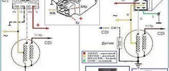
Scheme of the VAZ-2107 generator type 37.3701
- Accumulator battery.
- Generator.
- Voltage regulator.
- Mounting block.
- Ignition switch.
- Voltmeter.
- Battery charge indicator lamp.
When the ignition is turned on, the plus from the lock goes to fuse No. 10, and then goes to the battery charge indicator lamp relay, then goes to the contact and to the coil output. The second terminal of the coil interacts with the central terminal of the starter, where all three windings are connected. If the relay contacts close, then the control lamp lights up. When the engine starts, the generator generates current and an alternating voltage of 7V appears on the windings. Current passes through the relay coil and the armature begins to attract, and the contacts open. Generator No. 15 passes current through fuse No. 9. Similarly, the excitation winding receives power through the brush voltage generator.
Checking the combined relay-regulator of the car
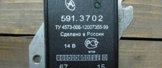
First we will check the combined relay-regulator circuit together with the brush assembly. These are now installed on many foreign cars, and by the way, on many domestic cars (often labeled Y212A).
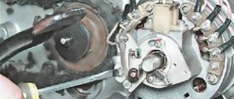
As you understand, it is necessary to remove the generator and disassemble it, since this combined unit is attached at the back next to the generator shaft, along which these brushes run. For this:
- We look for a special “window” on the back of the generator where the brushes are immersed.
- Unscrew the fastening bolt.
- Remove the brush assembly.
- We clean it - as a rule, it will be covered in graphite dust; the brushes are made of graphite, using special carbon.
Then we need to check it, but for this we assemble a certain circuit, it is advisable to use a power supply with an adjustable load or a charger. We also need to take a regular 12V light bulb from a car, for example from a “dimensions”, we will need wires to assemble the entire system.
We may need a battery, because many chargers do not work without it. But from the wire from the battery we connect the relay-regulator, to the brushes of which we connect a 12V light bulb, this can be done with small alligator clips, the main thing is not to break the graphite elements. A small diagram for understanding.
Read also: Autonomous diesel oven
If you connect everything in a calm state, the light will simply light up and stay lit, this is normal, since the brush assembly is a conductor of electricity from the shaft. Let me remind you that in a calm state, the voltage on the brushes will be approximately 12.7V.
Now we need to raise the voltage on the charger to 14.5 V, the lamp will light, but when this threshold is reached it should go out! That is, 14.5 V is a kind of “cutoff” for a further increase in voltage! If you lower the value, the lamp should light up again. Then your relay-regulator is working, it passed the test.
If the voltage reaches 15 - 16V and the light is on, this means the relay has failed and needs to be replaced! It does not cause a “cut-off” and will help recharge the battery. Here's a simple check. Now a short video on the topic.
Charging diagram for VAZ with injection engines
This scheme is identical to the schemes on other VAZ models. It differs from the previous ones in the method of exciting and monitoring the serviceability of the generator. It can be carried out using a special control lamp and a voltmeter on the instrument panel. Also, through the charge lamp, the generator is initially excited at the moment it starts working. During operation, the generator operates “anonymously,” that is, excitation comes directly from pin 30. When the ignition is turned on, power through fuse No. 10 goes to the charging lamp in the instrument panel. Then it goes through the mounting block to pin 61. Three additional diodes provide power to the voltage regulator, which in turn transmits it to the excitation winding of the generator. In this case, the indicator lamp will light up. It is at that moment when the generator operates on the plates of the rectifier bridge that the voltage will be much higher than that of the battery. In this case, the control lamp will not light up, because the voltage on its side on the additional diodes will be lower than on the side of the stator winding and the diodes will close. If the control lamp lights up while the generator is running, this may mean that additional diodes are broken.
Possible causes of failure of the regulator relay
Modern relay models have a relatively long service life. But some factors can lead to premature failure of the element, namely:
- Low quality of the part itself.
- The occurrence of a short circuit.
- Mechanical damage to the part.
The problem may also be caused by water ingress.
On some generator models, replacement of the electronic regulator relay will be necessary if the brushes are worn out. Under normal conditions, the life of the voltage regulator exceeds 60,000 km.
Checking generator operation
You can check the functionality of the generator in several ways using certain methods, for example: you can check the output voltage of the generator, the voltage drop on the wire that connects the current output of the generator to the battery, or check the regulated voltage.
To check, you will need a multimeter, a car battery and a lamp with soldered wires, wires for connecting between the generator and the battery, and you can also take a drill with a suitable head, since you may have to twist the rotor by the nut on the pulley.
How to check the relay - regulator without removing it from the car?
Indirect signs
If your “regulator” is out of order, you will notice it very quickly, especially if it is winter and frost outside. The fact is that there will be either an “undercharge” or an overcharge of the battery . If the charge is under-charged , you simply won’t start your car - you come to the parking lot, insert the key, and the car barely turns the engine, or doesn’t start at all, sometimes even the lights go out.
When recharging , almost the same thing will happen, only the reason will be boiling away of the electrolyte from the battery cans. It can be indirectly determined by the rapid decrease in electrolyte in the banks, and a white coating on the top of the battery, as well as on parts of the body underneath it. It’s worth thinking about it and checking the regulator relay.
However, this is not our method, we need to make sure more precisely.
Correct Method
To do this, we will use our voltmeter; we need to measure the voltage at the battery terminals with the engine running. To begin with, I would like to note that when the engine is not running, the normal voltage should be within 12.7V, perhaps a little less, but if you already have 12V, then the battery needs to be recharged! Or look for reasons for undercharging.
- Start the engine
- We set the multimeter to a value of up to 20 Volts
- Connecting the probes to the terminals
- If the voltage is approximately 13.2 - 14V, this is normal.
- We increase the speed (say to 2000 - 2500), the voltage will begin to increase, from about 13.6 to 14.2 V, this is also normal.
- Next, we try at maximum speed (more than 3500), the voltage should be from 14 to 14.5V, but no more!
If you have deviations, up or down, namely at any speed the voltage remains at 12.7V, or even drops to 12V, then this indicates a malfunction of the relay regulator.
Also, if the voltage is higher than 14.5V, for example - 15 - 16V, again the relay regulator is faulty and needs to be replaced.
To be completely honest, it is not always the relay that indicates a malfunction; often the generator itself fails. If the “regulator” is located separately, then you need to change it first; if nothing has changed, remove the generator and completely check the system. If the brush assembly is combined with the relay, then the generator must be removed!
The first signs of a malfunction of the relay regulator
How to check the generator relay regulator. The main sign of a deviation in the generator output voltage is difficulty starting the engine. This is especially true during the cold season. Check the battery. It must be clean and dry. There should be no white discharge on it. If they are present, then the regulator may have failed and the battery is being recharged, causing the electrolyte to boil.
The car's incandescent light bulbs are too bright. However, they often burn out. There is a smell of burnt wiring in the car interior. It is not uncommon for fuses to blow. When the headlights are on, the brightness of the light directly depends on the engine speed. All this suggests that the voltage stabilizer may have failed. It's simply a regulator. By the way, difficulty starting the engine can occur with both excess and insufficient voltage.
Watch the charging current indicator light. It is located on the instrument panel. Lights up red with the battery symbol. It can burn either at full heat or at half heat. When the engine is running, this indicates a generator malfunction.
Electrical failure of the generator can manifest itself in three ways:
- Complete absence of any tension.
- Severely low voltage.
- Extremely high voltage.
If any of the above problems occur, it is first recommended to check the functionality of the generator relay regulator.