I thought about this thing last winter, when short trips around the city (home-work, home-shop, etc.) with all consumers turned on began to make themselves felt. Many people have probably heard about installing a “boost diode on the voltage regulator,” and so, after reading this article, I thought: in this situation, the voltage in the on-board network is not manually regulated, it simply becomes greater by the value by which the voltage drops when current passes through a diode. First, a little theory: when current passes through a diode, the voltage drops by an average of 0.5 volts (depending on the diode), and the standard regulator thinks that the voltage has dropped in the on-board network and makes the generator produce more voltage. Practice: we take the same circuit as for the “boost diode” and add to it a second diode and a 3-position switch, and you can use any diode, just so that it is designed for a current of at least 5A, then we assemble everything like this scheme
And voila first position 14.2 V, second position 15.4 V, third position 14.8 V
The voltage stabilizer in the on-board electrical system of a car is the most important component without any exaggeration. Not only the stability and longevity of the battery will depend on the quality of its work. At the same time, even a completely serviceable stabilization device does not always guarantee compliance with the voltage and quality of power supply of the vehicle’s electrical network. Car enthusiasts often wonder how to make the generator voltage regulator relay more reliable - contact a service station specialist, assemble or improve it yourself? There are many options.
Modern stabilizers
On modern vehicles, as a rule, self-oscillating relays are installed. They work on the principle of turning off the power to the excitation coil when the voltage reaches the upper limit of 13.5-13.8 V and connecting at the lower voltage threshold of 14.5-14.6 V.
Thus, the output voltage fluctuates constantly. Theoretically, this is not considered a disadvantage, since the voltage does not exceed acceptable limits. Still, this is not entirely safe. Surely experienced drivers know that the weak point of this type of relay is the transition moments when the rotor speed or load current changes sharply. A particularly unfavorable moment occurs with a large load current at low speeds. At these moments, voltage fluctuations often exceed the upper threshold. Due to the short duration of such surges, the battery will not fail immediately, but each time its capacity and, accordingly, resource is reduced.
This problem is solved in different ways. Sometimes car enthusiasts simply replace the self-oscillating relay with an outdated contact-vibration relay. A more optimal solution would be to replace the relay with a pulse-width stabilizer or upgrade the “native” one with the help of small additions.
Solenoid valve for motorcycle Yamaha XV1600ASN Midnight Star (2001), XV1600ASNC Midnight Star (2001), XV1600AL Road Star (1999), XV1600ALC Road Star (1999), XV1600ALM Road Star Limited Edition (2000), XV1600ALMC Road Star Limited Edition (2000) , XV1600AM Road Star (2000), XV1600AMC Road Star (2000), XV1600AN Road Star (2001), XV1600ANC Road Star (2001), XV1600AP Road Star (2002), XV1600APC Road Star (2002), XV1600AR Road Star (2003), XV1600ARC Road Star (2003), XV1600ALER Road Star Limited Edition (2003), XV1600ASR Midnight Star (2003), XV1600ASRC Midnight Star (2003), XV17AWT Road Star (Cast Wheels) (2005), XV17AWTC Road Star (Cast Wheels) (2005) ), XV17AT Road Star (Spoke Wheels) (2005), XV17ATC Road Star (Spoke Wheels) (2005), XV17AS Road Star (2004), XV17ASC Road Star (2004), XV17AWW Road Star (2007), XV17AWWC Road Star (2007 ), XV17AWWC-F Road Star (with Flames) (2007), XV17AWV Road Star (Cast Wheels) (2006), XV17AWVC Road Star (Cast Wheels) (2006), XV17AMS Road Star Midnight (2004), XV17AMSC Road Star Midnight ( 2004), XV17AMT Road Star Midnight (2005), XV17AMTC Road Star Midnight (2005), XV17AMV Road Star Midnight (2006), XV17AMW Road Star Midnight (2007), XV17AMVC Road Star Midnight (2006), XV17AMWC Road Star Midnight (2007) , XV17ATMS Road Star Silverado (2004), XV17ATMSC Road Star Silverado (2004), XV17ATMT Road Star Midnight Silverado (2005), XV17ATMTC Road Star Midnight Silverado (2005), XV17ATMV Road Star Midnight Silverado (2006), XV17ATMW Road Star Midnight Silverado ( 2007), XVS1100AWR V-Star Classic Coast (Cast Wheel) (2003), XVS11AS V-Star Classic (2004), XVS11ASC V-Star Classic (2004), XVS11AWT V-Star Classic (2005), XVS11AWTC V-Star Classic ( 2005), XVS11AWW V-Star Classic (2007), XVS11AWXB V-Star Classic (2008), XVS11AWXCB V-Star Classic (2008), XVS11AWXCW V-Star Classic (2008), XVS11AWXW V-Star Classic (2008), XVS11AWYCG V -Star Classic (2009), XVS11AWYCR V-Star Classic (2009), XVS11AWYG V-Star Classic (2009), XVS11AWYR V-Star Classic (2009), XVS11AWWC V-Star Classic (2007), XVS11AWV V-Star Classic (Cast Wheel) (2006), XVS11S V-Star Custom (2004), XVS11W V-Star Custom (2007), XVS11XL V-Star Custom (2008), XVS11YR V-Star Custom (2009), XVS11W-M V-Star Midnight Custom (2007), XVS11V-F V-Star Custom (with Flames) (2006), XVS11T V-Star Midnight Custom (2005), XVS11XCB V-Star Midnight Custom (2008), XVS11ATS V-Star Silverado (2004), XVS1100AP V -Star Classic (2002), XVS1100PC V-Star Custom (2002)
art.: 4WM-14896-00-00 4WM148960000 4WM-14896-00
SHI stabilizer
Pulse-width stabilizers are characterized by more stable operation, that is, an almost constant voltage is supplied to the vehicle network, and small deviations within the normal range are smooth. The device circuit uses the same parts as in the original, but at the same time the K561TL1 microcircuit is included. This made it possible to assemble a multivibrator and a short pulse shaper on the 1st node. The output switch control unit has also been simplified due to the use of a field-effect transistor with increased power.
Stabilizer operation cycle
When the ignition is turned on, a low logic level appears at the output of trigger DD1.1. As a result, transistor VT1 opens with the charging current of the capacitor SZ. It, in turn, begins to supply a high level to the inputs of element DD1.2, simultaneously discharging capacitor C4. When a low level appears at the output, DD1.2 opens the field-effect transistor VT3. The current from the stabilizer output flows through the excitation winding of the generator.
After the pulse stops, a high level is formed at the output of DD1.1 and transistor VT1 closes. Capacitor C4 is charged by the current passing through resistor R5 from the generator, which is controlled by transistor VT2. While the voltage on capacitor C4 drops to the lower switching limit of trigger DD1.2, it will switch. A high level will appear at its output, which will close transistor VT3. In order to protect the input circuits of the DD1 microcircuit, the voltage of capacitor C4 is limited by the diode VD4, which, when it is subsequently charged, will not lead to switching DD1.2. When a low-level pulse is again formed at the output of the generator, the process begins to repeat.
Thus, stabilization is carried out by the duration of the on state of the field-effect transistor, and the process is controlled by a measuring device, as well as a current generator. When the voltage at the generator output increases, the collector current of transistor VT2 increases. As the amperage increases, capacitor C4 begins to charge faster and the duration of the on state of transistor VT3 decreases. As a result, the current that flows through the excitation winding of the generator decreases and, of course, the output voltage of the generator decreases.
When the voltage at the output from the generator decreases, the current at the collector of transistor VT2 decreases. As a result, the charging time of capacitor C4 increases. This leads to a longer period of switching on of the transistor VT3 and the current that flows through the excitation winding of the generator increases. The generator output voltage also increases.
Order payment methods
Cash
— you can pay for your order in cash when purchasing in a store or upon receiving an order from a courier service employee;
Cashless payments
— this payment method is possible for individuals and legal entities. To pay for your order, we issue you an invoice for payment, which you can pay from any bank branch;
Payment by bank card - we accept payments by plastic cards both when paying for goods directly in the store, and online through the cart of our online store
;
To pay for goods using a bank card, when placing an order, you must click the “Payment by bank card” button.
Payment is made through the authorization server of the Bank's Processing Center using Bank credit cards of the following payment systems:
When paying for goods through an online store, you need to enter:
- Your credit card number;
- Expiration date of your credit card, month/year;
- CVV code for Visa cards / CVC code for Master Card (last 3 digits on the back of the card):
If your card does not have a CVC / CVV code, then the card may not be suitable for CNP transactions (i.e. transactions in which the card itself is not present, but its details are used), and you should contact your bank for detailed information. information.
How the data transfer process occurs:
To pay for the purchase, you will be redirected to the payment gateway of Sberbank of Russia PJSC to enter your card details. Please prepare your plastic card in advance. The connection to the payment gateway and the transfer of information is carried out in a secure mode using the SSL encryption protocol.
If your bank supports the Verified By Visa or MasterCard Secure Code technology for secure online payments, you may also need to enter a special password to make a payment. You can check the methods and possibility of obtaining passwords for making online payments with the bank that issued the card.
This site supports 256-bit encryption.
Confidentiality of the reported personal information is ensured by PJSC Sberbank of Russia
.
The entered information will not be provided to third parties except in cases provided for by the legislation of the Russian Federation. Payments by bank cards are carried out in strict accordance with the requirements of Visa Int payment systems. and MasterCard Europe Sprl. When canceling an order:
When canceling items from a paid order (or when canceling the entire order), you can order another product for this amount, or return the entire amount to the card by first writing an e-mail or calling us.
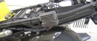
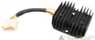
Voltage Regulator Upgrade
This is another option to improve the quality of the relay and its resistance to transient moments. The standard relay 50.3702-01 was taken as a basis, with only one resistor and capacitor added to the circuit.
In the diagram, the modification is indicated in red and, as you can see, does not require much effort or special experience in radio electronics. When the voltage in the on-board electrical network increases, capacitor C2 begins to charge. In this case, part of the current flows through the base of transistor VT1 and is proportional in magnitude to the rate of voltage increase. This leads to the opening of transistor VT1 and the closing of transistors VT2 and VT3. In this case, the current in the excitation coil decreases, and earlier than without an additional installed circuit. This allows you to significantly reduce voltage fluctuations in the network or eliminate them altogether. The same goes for reducing voltage. In other words, the permissible voltage limits are narrowed, and the smoothness of stabilization increases.
In this diagram, you can also introduce another rational proposal. As you know, the output voltage of the generator is optimized depending on the ambient temperature and in winter it should be higher by 0.8 V, reaching somewhere around 14.6 V. According to the standard, seasonal adjustment is performed by removing or installing jumpers S1, S2 and S3. Installing jumpers eliminates resistors R1, R2 and R3 from the circuit and the output voltage increases. When the jumpers are removed, the transistors turn on again and the voltage drops. To avoid this, the mentioned transistors can be replaced with one trimmer and the output voltage can be adjusted more easily and with greater accuracy.
A generator voltage regulator relay has been created to adjust the “voltage” supplied to the on-board network and to the battery terminals in a given range of 13.8 - 14.5 V (less often up to 14.8 V). In addition, the regulator adjusts the voltage on the self-excitation winding of the generator.
The secret to reassembling
To avoid the long and tedious hassle of installing the rotor into the housing, secure the brushes from moving out in their sockets with toothpicks, lubricate the rotor axles with some refractory grease, install the rotor in the housing and remove the toothpicks. This will make it much easier and faster, and most importantly, you won’t break or twist anything.
And one more thing: if after assembly the starter rotates in the other direction, do the following: unscrew the bolts holding the housing together and rotate the housing with magnets 180 degrees relative to the second half of the housing and the problem will go away.
Purpose of the voltage regulator relay
Regardless of experience and driving style, the car owner cannot ensure the same engine speed at different times. That is, the crankshaft of the internal combustion engine, which transmits torque to the generator, rotates at different speeds. Accordingly, the generator produces different voltages, which is extremely dangerous for the battery and other consumers of the on-board network.
Therefore, replacing the alternator regulator relay should be done when the battery is undercharged or overcharged, the light is on, the headlights are flashing and other interruptions in the power supply to the on-board network.
Interconnection of car current sources
The vehicle contains at least two sources of electricity:
- battery - required at the moment of starting the internal combustion engine and the primary excitation of the generator winding; it does not create energy, but only consumes and accumulates at the time of recharging
- generator – powers the on-board network at any speed and recharges the battery only at high speeds
Both of these sources must be connected to the on-board network for the correct operation of the engine and other electricity consumers. If the generator breaks down, the battery will last for a maximum of 2 hours, and without the battery, the engine driving the generator rotor will not start.
There are exceptions - for example, due to the residual magnetization of the excitation winding, the standard GAZ-21 generator starts on its own, subject to constant operation of the machine. You can start a car “from a pusher” if it has a DC generator installed; with an AC device, such a trick is impossible.
Voltage regulator tasks
From a school physics course, every car enthusiast should remember the principle of operation of a generator:
- when the frame and the surrounding magnetic field move mutually, an electromotive force arises in it
- The stators serve as the electromagnet of DC generators, the EMF, accordingly, arises in the armature, the current is removed from the collector rings
- In the alternating current generator, the armature is magnetized, electricity appears in the stator windings
In a simplified way, we can imagine that the magnitude of the voltage output from the generator is influenced by the value of the magnetic force and the speed of rotation of the field. The main problem of DC generators - burning and sticking of brushes when removing large currents from the armature - has been solved by switching to alternating current generators. The excitation current supplied to the rotor to excite magnetic induction is an order of magnitude lower, making it much easier to remove electricity from a stationary stator.
However, instead of terminals “–” and “+” constantly located in space, car manufacturers received a constant change in plus and minus. Recharging the battery with alternating current is not possible in principle, so it is first rectified with a diode bridge.
From these nuances the tasks solved by the generator relay flow smoothly:
- adjusting the current in the excitation winding
- maintaining a range of 13.5 - 14.5 V in the on-board network and at the battery terminals
- cutting off the power to the excitation winding from the battery when the engine is turned off
Therefore, the voltage regulator is also called a charging relay, and the panel displays a warning light for the battery charging process. The design of alternating current generators includes a reverse current cut-off function by default.
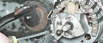
Cleaning the collector
We place the rotor on some clean surface, preferably wooden, and use any suitable needle to clean out the dirt between the collector lamellas.
After cleaning, take a piece of some lint-free cloth, thoroughly moisten it in clean gasoline, wrap it around the commutator and begin to rotate the rotor commutator in it. It is not necessary to rub the collector much; it will be enough just to wash it from dirt to approximately the same condition as in the photo.
Types of regulator relays
Before you independently repair the voltage regulation device, you must take into account that there are several types of regulators:
- external – increase the maintainability of the generator
- built-in – in the rectifier plate or brush assembly
- regulating by minus - an additional wire appears
- positive regulating – economical connection scheme
- for alternating current generators - there is no function for limiting the voltage on the excitation winding, since it is built into the generator itself
- for DC generators – an additional option for cutting off the battery when the internal combustion engine is not working
- two-level - obsolete, rarely used, adjustment by springs and a small lever
- three-level – supplemented with a special comparison device board and a matching indicator
- multi-level - the circuit has 3 - 5 additional resistors and a tracking system
- transistor - not used in modern cars
- relay – improved feedback
- relay-transistor - universal circuit
- microprocessor - small dimensions, smooth adjustment of the lower/upper threshold of operation
- integral - built into brush holders, therefore they are replaced after the brushes wear out
Procedure for returning and exchanging goods
Return Policy
The product is accepted for return/exchange if:
- a claim regarding the quality of a product is made before the expiration of the product’s warranty period - the guarantee provided by:
- The law of the Russian Federation is 14 days, not counting the date of purchase (in accordance with the Federal Law of the Russian Federation, Article 25, clause 2, paragraph 2);
- Warranty provided by the motorcycle and bicycle market “Tourist”;
- Warranty provided for the product by the manufacturer;
- the detected defect is not a consequence of improper use of the product - there is a cash register or sales receipt (FZoPP, Article 25, clause 1, paragraph 3);
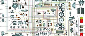
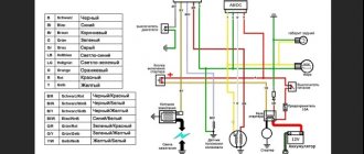
ELECTRONICS OF ALPHA AND DELTA MOPEDS
Due to the fact that more and more owners of devices with engines of the 139FMB type and lights at recess are faced with six-coil generators (replacing the motor or preferably a more powerful generator), there is a need to write this article. First, let's figure out what the differences are. The picture shows a diagram
The electrical equipment of the mopeds under consideration consists of a source and consumers of electronic energy, auxiliary devices and an electronic network. Electrical equipment ensures timely ignition of the working mixture in the engine cylinder, operation of lighting devices and
Operating principle of the regulator relay
Thanks to built-in resistors and special circuits, the relay is able to compare the amount of voltage generated by the generator. After which, too high a value leads to the relay being turned off, so as not to overcharge the battery and damage electrical appliances connected to the on-board network.
Any malfunctions lead to precisely these consequences: the battery becomes faulty or the operating budget increases sharply.
Summer/winter switch
Regardless of the season and air temperature, the operation of the generator is always stable. As soon as its pulley begins to rotate, electric current is generated by default. However, in winter the insides of the battery freeze, and it replenishes the charge much worse than in summer.
The summer/winter switches are either on the body of the voltage regulator, or the corresponding connectors are marked with this designation, which you need to find and connect the wiring to them depending on the season.
There is nothing unusual in this switch, these are just rough settings of the regulator relay, which allows you to increase the voltage at the battery terminals to 15 V.
Connection to the generator's on-board network
If, when replacing a generator, you connect a new device yourself, you need to take into account the following nuances:
- First you should check the integrity and reliability of the contact of the wire from the car body to the generator housing
- then you can connect terminal B of the regulator relay with the “+” of the generator
- Instead of “twists” that begin to heat up after 1–2 years of operation, it is better to use soldering of wires
- the factory wire must be replaced with a cable with a minimum cross-section of 6 mm2 if, instead of a standard generator, an electrical appliance rated for a current of more than 60 A is installed
- The ammeter in the generator/battery circuit shows which power source is currently higher in the on-board network
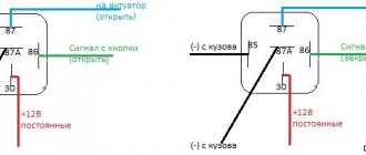
Electronics protection
Starting the engine causes a voltage drop in the starting battery circuit. If the engine is started while the batteries are combined, a voltage surge may also be felt in the service battery circuit. Harsh transients can not only reset GPS and navigation equipment, but also damage sensitive electronics. It is therefore important that the batteries are isolated at this point.
Isolation relay connection diagram. To protect expensive electronics from power surges that occur when starting the engine, the relay is connected to the starter solenoid. As soon as voltage appears on it, the relay disconnects the batteries
Some relay models have this feature. When the ignition key is turned, voltage from the ignition switch is applied to the starter solenoid and the Start Interlock relay connector. The relay opens and disconnects the batteries before the engine starts. It will reconnect the batteries only after the starter stops working. The same relay connector can be used to control the device remotely.
Regulator relay diagnostics
Voltage regulator failures can be determined by indirect signs. First of all, this is incorrect battery charging:
- overcharge - the electrolyte boils away, the acid solution gets on the body parts
- undercharging - the internal combustion engine does not start, the lamps are dimly lit
However, it is preferable to diagnose with instruments - a voltmeter or tester. Any deviation from the maximum voltage value of 14.5 V (in some cars the on-board network is designed for 14.8 V) at high speeds or the minimum value of 12.8 V at low speeds becomes the reason for replacing/repairing the regulator relay.
Built-in
Most often, the voltage regulator is integrated into the generator brushes, so a level inspection of this unit is necessary:
- After removing the protective cover and loosening the screws, the brush assembly is removed out
- When the brushes are worn out (less than 5 mm of their length remains), replacement must be carried out without fail.
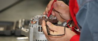
- Generator diagnostics with a multimeter are carried out complete with a battery or charger
- The “negative” wire from the current source is closed to the corresponding regulator plate
- The “positive” wire from the charger or battery is connected to a similar relay connector
- the tester is set to voltmeter mode 0 - 20 V, the probes are placed on the brushes
- in the range of 12.8 - 14.5 V there should be voltage between the brushes
- when the voltage increases above 14.5 V, the voltmeter needle should be at zero
In this case, instead of a voltmeter, you can use a lamp, which should light in the specified voltage range and go out when this characteristic increases above this value.
The wire that controls the tachometer (marked W only on relays for diesel engines) is tested with a multimeter in tester mode. It should have a resistance of about 10 ohms. If this value decreases, the wire is “broken” and should be replaced with a new one.
Remote
There are no differences in diagnostics for the remote relay, but it does not need to be removed from the generator housing. You can check the generator voltage regulator relay with the engine running, changing the speed from low to medium, then high. Simultaneously with the increase in speed, you need to turn on the high beams (at a minimum), the air conditioner, the monitor and other consumers (at a maximum).
Thus, if necessary, the vehicle owner can replace the standard voltage regulator relay with a more modern modification of a built-in or remote type. Diagnostics of performance is available on your own with a regular car lamp.
Scooter starter malfunctions: identifying and fixing the problem
The presence of a starter in a scooter, unlike a car, is not mandatory. However, it makes life much easier for the driver, adding a little comfort while working. Everyone knows that the starter works thanks to the battery, and it consists of:
The principle of its operation is no different from any other starter, although some breakdowns may differ from the usual ones.
Why doesn't the starter work?
Initially, you need to exclude battery discharge from the list of possible breakdowns. If this were the case and the battery suddenly became low, you would hear a peculiar sound when you press the “start” button. This sound indicates that the starter is not engaged with the bendix and is running without load, idle. If you still hear this sound when starting up, do certain things:
In most cases, these points will help you solve the problem with your scooter.
However, there may be other breakdowns, which in themselves are considered more serious when compared to a dead battery. We are talking about audible clicks when the starter operates. This is a deeper problem and it is necessary to look for its causes.
Causes and solutions
Step 1: With the ignition on, try honking the horn. If everything worked out and you could hear a loud and ringing sound, everything is fine, you can start the engine. If the sound was very quiet or could not be heard at all, there were problems with the battery or power supply (recharge the battery, clean the terminals).
Step 2. When you press the engine start button, you hear the sound of the relay turning on. If yes, then try bridging the power terminals of the relay. If there is no sound, disconnect the relay from the power supply, and then use the wires to connect the battery and starter.
Step 3. Once you have connected the starter, it works fine. If yes, then you just need to replace the relay. If not, check the contacts of the start button, the wires from the starter, and replace all worn parts.
Moped maintenance
Like any vehicle, Alpha mopeds require routine maintenance, the essence of which boils down to:
- Replacement of parts and assemblies whose service life has expired;
- Setting up and restoring the factory parameters of the main components and assemblies;
- Visual inspection of the moped to identify damage.
Chinese engines quite confidently “maintain” 20,000 km on our domestic fuels and lubricants without breakdowns or overhaul of the piston group. The main thing is to change the oil in a timely manner, especially during the break-in period.
If you do not operate the moped in harsh conditions (winter, cross-country racing, etc.), then all oil seals and rubber seals will also last a long time.
Tip: Change your air filter often. This will save the carburetor and make it easier to start the engine in all operating modes.