How to replace the turn signal relay on a scooter - Scooter-Expert - online magazine about scooters and technology
A turn signal relay on a scooter is a necessary attribute for the correct operation of the turn indicators.
If the turn signals suddenly change their blinking frequency, do not blink at all, or freeze in the on position, even though the wiring, battery and bulbs are in good working order, it is obvious that the turn signal relay needs to be replaced. Depending on the scooter model, its location can vary from the space under the front plastic to the rear of the scooter. As a rule, the manufacturer tries to place the turn signal relay under the front plastic. In appearance, it is a small rectangular, cylindrical or square plastic object that resembles a starter relay in appearance. Let's take a step-by-step look at how to properly replace the turn signal relay on a scooter:
- We install the scooter on the central support.
- We determine the location of the turn relay specifically on your scooter; for this you can use the instruction manual for your model.
- The part is usually attached to the scooter frame with rubber clamps. We remove the relay.
- Carefully disconnect the plastic relay connector. Usually it is connected directly to the body of the part, without additional wiring, however, on some models you can find the example shown in the photo above.
- We connect a new turn relay to the on-board network and install it in place.
- All other plastic assembly operations are performed in the reverse order of disassembly.
How to replace the voltage regulator relay on a scooter
The voltage regulator on a scooter is an important element to ensure the normal operation of electrical equipment. It is he who is responsible for supplying a voltage of a certain nominal value to electricity consumers in the scooter’s on-board system.
Replacing the voltage regulator relay on a scooter may be necessary if the device fails.
One such example is stopping the supply of charging current to the battery contacts while the generator is working properly.
Let's take a step-by-step look at how to properly replace a scooter's voltage regulator on your own:
- We install the scooter on the central support.
- We determine the location of the voltage regulator relay in the device of your scooter model. If you do not have such information, use the manual for your device.
- Depending on the location of the part, the necessary elements of the scooter lining are dismantled. In some cases, you will need to remove the front plastic, sometimes the regulator is located in the back, and often its place is in the area under the “toilet”. For the latter case, it is enough to remove the seat area along with the seat to find the treasured regulator. Typically, this is a small aluminum device, slightly larger than a matchbox, with cooling fins to dissipate heat. The electrical connector goes to it.
- So, we have determined where the voltage regulator is located on the scooter; all that remains is to carefully replace it. Its body is usually attached to the frame or other components of the scooter using a bolt, rarely a self-tapping screw. The bolt can be an open-end wrench, often a hex wrench. We unscrew the relay from its seat, without losing the fasteners.
- Disconnect the connector chip.
- The new voltage regulator must fully correspond to the markings of the stock version, have a similar pinout and connector. When purchasing a part in a store, be sure to indicate the model of your scooter. If the seller has an idea about the product he is selling, choosing the necessary spare part will not be difficult for him. We connect the relay regulator to a standard connector.
- We install the part in its normal place, securing it with a fastener.
- We assemble the remaining parts of the scooter, for example, the plastic lining, in the reverse order of disassembly.
Emergency button
Sometimes the described manipulations do not make the emergency lights function. In this situation, you should draw an unambiguous conclusion - on your VAZ-2114 it is the button that turns it on that has broken down. Actually, the mechanism itself almost never fails, but the wires soldered to it often come off. If the signal, when the veins are directly closed, is in emergency mode and acts as it should, then there is no need to blame the fuse and relay. Handle the button, inspect its contacts and check whether the cable is securely attached to them.
First, ring the positive wire. Do this with the hazard lights and ignition on. When the tester does not confirm the presence of a positive charge, then it is time to check the cables connected to the button in the area between it and the dashboard.
The presence of current on the positive makes it possible to close the terminals of the control element directly (do not forget to turn on the ignition). After this, try activating the turn signals again. Their performance indicates a failure of the button itself - it cannot be repaired, just install a new one. If there is no power at all, then look for a problem in the relay or wires running from the mounting block to the button.
Electrics and electrical equipment of a scooter
Dedicated to all owners of Chinese scooters...
To begin with, I would like to present a wiring diagram for a Chinese scooter.
Since all Chinese scooters are very similar, like Siamese twins, their electrical circuits are practically no different.
The diagram was found on the Internet and is, in my opinion, one of the most successful, since it shows the color of the connecting conductors. This greatly simplifies the diagram and makes it more comfortable to read.
(Click on the image to enlarge. The image will open in a new window).
It is worth noting that in the electrical circuit of a scooter, just like in any electronic circuit, there is a common wire. On a scooter, the common wire is the minus (—). In the diagram, the common wire is shown in green. If you look more closely, you will notice that it is connected to all the electrical equipment of the scooter: headlight (16), turn relay (24), instrument panel backlight lamp (15), indicator lamps (20, 36, 22, 17), tachometer (18 ), fuel level sensor (14), horn (31), tail light/brake light (13), start relay (10) and other devices.
First, let's go over the main elements of the Chinese scooter circuit.
Egnition lock.
Ignition switch (12) or “Main switch”. The ignition switch is nothing more than a regular multi-position switch. Even though the ignition switch has 3 positions, the electrical circuit uses only 2.
When the key is in the first position, the red and black wires are connected. In this case, the voltage from the battery enters the electric circuit of the scooter, the scooter is ready to start. The fuel level indicator, tachometer, sound signal, turn relay, and ignition circuit are also ready for operation. They are supplied with power from the battery.
If the ignition switch malfunctions, it can be safely replaced with some kind of switch like a toggle switch. The toggle switch must be powerful enough, because the entire electrical circuit of the scooter is, in fact, switched through the ignition switch. Of course, you can do without a toggle switch if you limit yourself to short-circuiting the red and black wires, as the heroes of Hollywood action films once did
In the other two positions, the black and white wire from the CDI ignition module (1) is shorted to the housing (common wire). In this case, engine operation is blocked. In some scooter models, to block the engine, there is an engine stop button (27), which, like the ignition switch, connects the white-black and green (common, body) wire.
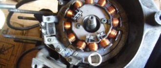
Generator.
The generator (4) produces alternating electric current to power all current consumers and charge the battery (6).
There are 5 wires coming from the generator. One of them is connected to a common wire (frame). The alternating voltage is removed from the white wire and supplied to the relay regulator for subsequent straightening and stabilization. The yellow wire removes voltage, which is used to power the low/high beam lamp, which is installed in the front fairing of the scooter.
Also in the design of the generator there is a so-called hall sensor. It is not electrically connected to the generator and there are 2 wires coming from it: white-green and red-black. The hall sensor is connected to the CDI ignition module (1).
Relay regulator.
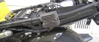
Regulator relay (5). People may call it a “stabilizer”, “transistor”, “regulator”, “voltage regulator” or simply “relay”. All these definitions refer to one piece of hardware. This is what the relay regulator looks like.
The relay regulator on Chinese scooters is installed in the front part under a plastic fairing. The relay-regulator itself is attached to the metal base of the scooter in order to reduce the heating of the relay radiator during operation. This is what the relay regulator looks like on a scooter.
In the operation of a scooter, the relay regulator plays a very important role. The task of the relay regulator is to convert the alternating voltage from the generator into direct voltage and limit it to 13.5 - 14.8 volts. This is the voltage required to charge the battery.
The diagram and photo show that there are 4 wires coming from the relay-regulator. Green is the common wire. We have already talked about it. Red is the output of positive DC voltage 13.5 -14.8 volts.
The regulator receives alternating voltage from the generator through the white wire to the relay. Also connected to the regulator is a yellow wire coming from the generator. It supplies the regulator with alternating voltage from the generator. Due to the electronic circuit of the regulator, the voltage on this wire is converted into a pulsating one, and is supplied to powerful current consumers - the low and high beam lamps, as well as the dashboard backlight lamps (there may be several of them).
Turn signal relay
Category: Auto electronics
The turn signal relay is capable of operating from 12 and 6 V power sources (suitable for installation on many motorcycle models). The frequency of turning on lamps and sound signals is 1 s. TO ENLARGE (REDUCE) THE DIAGRAM, CLICK ON THE PICTURE
The schematic diagram of the device is shown in the figure. A master oscillator operating at an audio frequency of 1 kHz is assembled on a DD1 chip of type KR512PS10. From the output Q1 of the MS counter, rectangular pulses with a frequency of 1 Hz are supplied to the input of a key current amplifier using transistors VT1-VT4. The base of transistor VT1 also receives (via resistor R2) pulses with a frequency of 1 kHz from the master oscillator. The parametric stabilizer VD1R3 serves to supply DD1 with a stable voltage. The key current amplifier is powered by an unstabilized on-board voltage. The total current consumption of the device when the signal lamps are turned off does not exceed 7 mA, so there is no power switch in the relay.
After turning on the direction indicator (switch SA1 to position, for example, “P” - turn to the right), the composite transistor VT3VT4 begins to open periodically, entering saturation. The time during which it is saturated is 0.5 s. Over the next 0.5 s, a transistor with a frequency of 1 kHz transitions from the active state to the closed state. The voltage form on the signal lamps is shown in the figure (for on-board network voltage Ubc=6V). TO ENLARGE (REDUCE) THE DIAGRAM, CLICK ON THE PICTURE
During the half-cycle, the voltage on lamps HL3, HL4 (Uл) is constant and equal to 5.5 V, so they glow at full heat. During the second half-cycle, the voltage Ul (a sequence of short pulses with a frequency of 1 kHz) of the lamps practically does not illuminate, although their filaments remain hot. In this case, the voltage drop across lamps HL3, HL4 is transmitted through diode VD2 to sound emitter HA1, which reproduces an audio signal with a frequency of 1 kHz. With an on-board network with a voltage of 12 V, resistor R3 should be replaced with another one (1.5 kOhm at a power of 1 W). You can reduce the volume of the signal by connecting a resistor with a resistance of 51...82 Ohms in series with NA1. You can use resistors of types MT, OMLT, S2-ZZA with a power of at least 0.25 W. Capacitor C1 - KLS, KM or K10-17. Transistors KT315V can be replaced with KG312A, KT608A, KT603A; KT313B - on KT630G; GT806A - to GT701A. Instead of a composite transistor (VT3-VT4), you can use KT825A or KT825B, and instead of KD102B diodes, you can use any others with a direct current of at least 0.3. A telephone capsule with a resistance of at least 50 Ohms is suitable as a sound emitter. Switch SA1 - toggle switch P2T-14 or any other with a middle position and a permissible current through the contacts of at least 4 A. All parts of the turn signal relay, except the toggle switch and capsule, are mounted on a printed circuit board made of foil fiberglass 1.5 mm thick. The VT4 transistor should be installed on a massive heatsink attached to the board. The board and capsule are placed in a box made of sheet duralumin, which is secured in a place convenient for the driver. With proper installation and serviceable parts, the relay does not need to be adjusted. If the on-board network has alternating voltage, the key current amplifier should be powered through a rectifier, and the microcircuit - from three galvanic elements 316,343,373 or from a battery 3336. In this case, there is no need for a parametric stabilizer. For more stable operation of transistor VT4, its emitter junction should be shunted with a resistor with a resistance of 200...300 Ohms and a power of 1 W.
rele_ukazatelja_povorotov
Method for checking the voltage regulator of a scooter
Chinese scooters are designed in such a way that their relay-regulator, which is also called a voltage regulator, often burns out. The voltage regulator is an electrical circuit with 4 terminals for connecting to the scooter's electrical network.
A malfunction of the voltage regulator leads to very disastrous consequences:
At first, the instrument panel backlight lamps and the central low/high beam lamp burn out. This happens due to the fact that the voltage from the generator is not limited to 12 volts, which leads to the lamps receiving an increased voltage of 16 to 27 volts and higher. The voltage supplied to the lamps fluctuates and depends on the engine speed. Even at idle, the lamps shine so much that they blind, although they should shine at half their maximum brightness.
If you do not remove the malfunction of the voltage regulator and leave everything as is (many do this - they just drive without lights), then over time the battery will fail because its charging voltage exceeds the permissible one. If the voltage regulator is faulty, the battery receives a voltage of more than 15 volts, while the standard charging voltage should be between 13.5 - 14.8 volts. All this leads to the fact that the battery begins to leak - acid begins to penetrate through the valves. This is noticeable to the naked eye. And although when the normal charging mode is restored, the battery restores its operation, its service life is sharply reduced.
Also, if the voltage regulator is faulty, the battery stops charging correctly and loses its capacity. Therefore, it is not possible to start the scooter with the button. You have to start it from kickstarter.
I think it’s now clear how important it is to change a faulty voltage regulator on a Chinese scooter.
How to check the voltage regulator on a scooter? It is best (and most reliable) to do this without dismantling the voltage regulator itself. We will need at least some kind of multimeter with a voltmeter function. Any ordinary DT-830 or similar will do. What should be done? It is necessary to measure the voltage at the output of the voltage regulator.
How to check the charging relay, voltage regulator
In this video I will show you how to check
two-phase
relay voltage regulator
, also called charging relay...
How to check if the relay regulator on a motorcycle is working?
How to check
Is the bike's alternator working? — .
All measurements were carried out on a Chinese scooter ABM Storm L ZW50QT-16.
To get to the relay-regulator, unscrew the front fairing in which the central headlight is installed. We find there on the frame a box with 4 terminals: red, green, yellow and white.
We put the scooter on the stand and start it. After some time, the engine operation stabilizes at idle. Next, measure the voltage between the green and red wires. We set the multimeter in DC voltage measurement mode to the limit of 20V. Here's a look at how you can do it.
The display should display a voltage of about 14.6 - 14.8 volts, as in the photo. This is normal, standard voltage.
Then we need to measure the voltage that goes to the lighting lamps. The voltage to the central high/low beam lamp is not constant, but alternating (pulsating), so we switch the multimeter to the 20V alternating voltage measurement mode. On the multimeter that I used (Victor VC9805A+), you need to press the DC/AC (Alternating Current) button to do this. After this, we measure the voltage between the green and yellow wires. We simply move the probe from the red to the yellow wire, since the green wire is the common wire in the scooter’s electrical network.
The multimeter display should show a voltage of around 12 volts. It showed 11.4 - 11.6 volts. This is normal as the scooter is idling. If you have an assistant, you can ask him to accelerate a little to increase the engine speed and, consequently, the voltage from the generator. In any case, the voltage should not change much and should be around 12 volts.
This was a voltage measurement at the output of a working voltage regulator (relay regulator).
Now let’s see what a voltmeter shows when measuring the voltage at the output of a faulty scooter voltage regulator.
conclusions
Of course, in order to carry out a proper connection or upgrade, you need to know where your car's turn signal relay is located. In most models it is mounted in the fuse box. But some manufacturers put it behind the dashboard, even in the steering column. Therefore, before starting all work, make sure that you know what you are doing, study the electrical and wiring diagrams so as not to make mistakes.
Recently, LED automobile lamps have become used. They are more durable and consume less current. The latter precisely affects the operation of the turn relay, changing its frequency. The frequency of relay operation is tied to the load resistance, that is, to the installed lamps. As the load resistance increases, which is exactly what happens when one of the lamps burns out or opens, the relay begins to operate most often. The same effect is observed when installing LEDs in direction indicators, since their power consumption is less, which means the resistance is much greater.
After studying the material in this article, you will be able to modify the standard turn signal relay for LEDs so that it operates at the frequency you need.
First of all, a little about the standard relay. The 3-pin turn signal relay which will be discussed is installed on cars starting from VAZ 2108 to the present, that is, on VAZ 2109, 2110, 2111, 2112, Lada Priora, Lada Kalina, GAZ cars. Marking 495.3747-ХХ.
To modify the relay, it will be necessary to open the housing. To do this, take a flat-blade screwdriver and remove the housing cover by pulling the plastic latches from two opposite sides.
Now let’s figure out what is responsible for what in this circuit and how we can change the operation so that with increased load the frequency of operation of the direction indicators does not change. The first is connection. Ground is connected to pin 31. 49a - output to lamps, 49 - input “+” from the turn signal switch.
R3 is a current-limiting resistor to the control base of the transistor in the microcircuit; R1 and C11 - these are the radio elements that are responsible for the frequency of the output signal from pin 3 of the microcircuit. From leg 3 power is supplied to the relay winding; Conclusion 7 is also an interesting conclusion. The output controls the change in resistance and, accordingly, voltage at contact 49 a. It is he who gives the command to the microcircuit to change the frequency when the lamps burn out. The microcircuits can be not only those indicated on the diagram, but also, for example, KR1055GP1B, etc. analogues.
Now, presenting the functional purpose of the relay elements, it is not difficult to decide on measures to maintain the frequency of operation of the direction indicators when their internal resistance changes, that is, for example, when installing LEDs.
It is possible to change the capacitance value, double it (replacing it with a 4.7 µF capacitor instead of 2.2 µF - in the photo the capacitance is increased due to parallel connection of an additional capacitor to the standard one), but in this case the alarm system does not work correctly.
It will operate at half the frequency. The option of changing the resistance is also not entirely successful. Since, in fact, here you will have to empirically select a current-limiting resistor at pin 4, which is also not a very good option.
Turning relay switching diagram 495.3747
There remains the last and perhaps the best way out. In fact, remove control over load resistance. By cutting the foil on the printed circuit board (red line) going to pin 7 of the microcircuit, we will get a stable frequency response of the direction indicators.
After this modification, resistor R2 must be reduced to 60 - 200 Ohms.
The only drawback of this modification of the relay for LEDs will be the lack of monitoring of burnt-out LEDs, since we have actually removed the dependence of frequency on load resistance.
Turn signals play an important role in road safety, and their failure can lead to a lot of trouble. A small device - a turn relay - is responsible for the operation of the turn signals. Read about what types of turn relays are used in VAZ cars, how they are designed and work, as well as about their malfunctions and repairs in this article.
Scooter alternator voltage test
If you have a multimeter, you can check the output voltage of the generator. A good battery will have a voltage greater than its rated voltage level even if it is completely discharged and allowed to sit for a few minutes or if it is in storage.
If the battery does not recover above its rated voltage level within a few minutes after being discharged, this indicates a faulty or worn-out battery. When the battery is fully charged and its voltage is below the rated voltage level, this also indicates a faulty or worn-out battery. Good scooter batteries will return above their rated voltage level within a few minutes of starting the scooter.
Look for any burnt or melted wires or wire connectors on the speed controller. If any wires are burned or melted, the speed controller may be faulty. Smell the speed controller for any burning smells. If the speed control smells, it is almost always faulty.
Speed controller
If the ESC doesn't have burnt or melted wires and doesn't smell, it may still be bad. Check all other electrical system components around the speed controller and use the elimination process to determine whether the speed controller is working or not. Speed controllers are too complex to be easily tested. Using a professional diagnostic is the best way to determine whether the ESC is working or not. If all other components of the electrical system are fine, but the scooter does not work, this indicates a faulty speed controller.
You can also watch some videos
Voltage regulator or as it is also called relay regulator
This piece of electrical equipment is very important and the longevity of the battery and other electrical appliances depends on it. The relay performs the function of a voltage stabilizer at the level that the generator produces, then this voltage goes to all the scooter devices that use it
If the voltage regulator was faulty or missing from the scooter, the voltage would jump and all the devices would quickly burn out. The regulator keeps the voltage within certain limits, preventing it from rising and falling too much, usually within the range of 12-14.5 volts. For example, incandescent lamps suffer significantly even from an increase in voltage of 2 volts.
The generator can produce 35 volts, and the regulator resets this voltage to 12 volts. To charge a scooter battery, you need direct current; it is the regulator that turns alternating current into direct current. Therefore, you need to look at the condition of the scooter’s voltage regulator very carefully so as not to cause trouble. One of the ways to understand that the relay regulator has failed is that the light bulbs quickly burn out. They themselves have a fairly high resource and durability, but at the same time they are sensitive to voltage drops. By the way, when starting the scooter from the starter, a strong surge in voltage occurs, which can also cause harm, but the regulator on the scooter again corrects this situation.
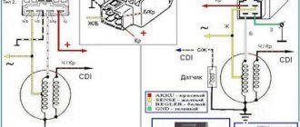
Different scooter manufacturers supply different relay regulators, since each model requires an individual one. Depending on the voltage regulator circuit, the connectors may also differ.
The voltage regulator relay on a Chinese scooter differs from the Japanese one even in the number of terminals. So, in Chinese there are 5 of them (dad), but in Japanese there are only 4.
But the general principle of operation of the voltage regulator is almost the same in all of them and performs the role of switching voltage using a powerful thyristor, turning on and off the voltage from the generator.
Regulator diagram on Japanese scooters:
Generator VAZ 2106: purpose and functions
A car generator is a small electrical device whose main task is to convert mechanical energy into electrical current. In the design of any car, a generator is needed to charge the battery and feed all electronic devices while the engine is running.
How exactly does the generator work on a VAZ 2106? All processes of energy conversion from mechanical to electrical are carried out according to a strict scheme:
- The driver turns the key in the ignition.
- Immediately, the current from the battery through the brushes and other contacts enters the excitation winding.
- It is in the winding that the magnetic field appears.
- The crankshaft begins to rotate, from which the generator rotor is also driven (the generator is connected to the crankshaft by a belt drive).
- As soon as the generator rotor reaches a certain rotation speed, the generator enters the self-excitation stage, that is, in the future, all electronic systems are powered only from it.
- The generator performance indicator on the VAZ 2106 is displayed in the form of a control lamp on the dashboard, so the driver can always see whether the device has enough charge for full operation of the car.
Design of the G-221 generator
Before talking about the design features of the VAZ 2106 generator, it should be clarified that it has unique clamps for mounting on the engine. On the body of the device there are special “ears” into which studs are inserted and tightened with nuts. And so that the “ears” do not wear out during operation, their internal parts are equipped with a high-strength rubber gasket.
The generator itself consists of several elements, each of which we will now consider separately. All these devices are built into a light-alloy cast housing. To prevent the device from overheating during long-term operation, the case has many small holes for ventilation.
Winding
Due to the fact that the generator has three phases, windings are installed in it immediately. The purpose of the windings is to generate a magnetic field. Of course, only special copper wire is used for their manufacture. However, to protect against overheating, the winding wires are covered with two layers of heat-insulating material or varnish.
Relay regulator
This is the name of the electronic circuit that controls the voltage at the output of the generator. The relay is necessary to ensure that a strictly limited amount of voltage reaches the battery and other devices. That is, the main function of the relay regulator is to control overloads and maintain an optimal voltage in the network of about 13.5 V.
Rotor
The rotor is the main electric magnet of the generator. It has only one winding and is located on the crankshaft. It is the rotor that begins to rotate after the crankshaft starts and gives movement to all other parts of the device.
Generator brushes
The generator brushes are located in brush holders and are needed to generate current. In the entire structure, it is the brushes that wear out the fastest, since the main work of generating energy falls on them.
Diode bridge
A diode bridge is most often called a rectifier. It consists of 6 diodes that are placed on a printed circuit board. The main job of a rectifier is to convert alternating current into direct current to maintain stable operation of all electronic devices in the car.
Pulley
The pulley is the driving element of the generator. The belt is tensioned simultaneously on two pulleys: the crankshaft and the generator, so the operation of the two mechanisms is continuously interconnected.
Modifying the relay (optional)
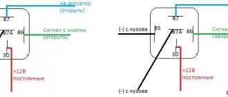
When the relay winding is turned off, a powerful inductive voltage surge occurs, which, at zero break current in the case of switching by mechanical contact, as in this case, can reach hundreds of volts. If the circuit is opened by the seat belt, a spark will jump between the contacts of switch SA1 in the belt buckle. If the ignition circuit is open, the spark will be somewhere in the ignition switch. You don’t have to worry about the ignition switch, but the belt buckle probably has a low-current contact that is not designed for switching an inductive load. To protect it, it is advisable to install a diode in parallel with the relay winding. In the diagram it will look like this (diodes D1 and D2, type 1N4007):
It is interesting that relays that are identical in characteristics, form factor and purpose of contacts can have different designs. Here is a photo of my relays with the cover removed, series 75.3777-10 and 98.3777-10. In the 75 series, the possibility of installing a protective diode or resistor is already provided by the manufacturer; there is a terminal holder and a clamp contact. And in the 98th series all that remains is to solder.
GENERATOR 700 W | OPPOZIT.RU | motorcycles Ural, Dnepr, BMW
The resistance between the windings must be the same. The engine is started and the rotor rotates in the stator winding, voltage is supplied to the excitation winding through the PP and the generator is excited.
As practice has shown, pieces of nails driven into holes cope with the task. If the voltage is outside the technical specifications, replace the regulator. In particular, automatic ignition timing was introduced, since the motorcycle received a new power unit, and the old manual control of the timing advance did not meet the technical requirements. The voltmeter reading is noted and, by bending the shank in the voltage relay, the spring tension is increased, and with it the generator voltage by 0.4 V. An additional rectifier arm is also introduced into the electrical circuit. During this period, you can slightly increase the generator voltage.
On a URAL car there is a voltage regulator. If the voltage is outside the technical specifications, replace the regulator. Adjust the position of the front wedge stops 9 on the closed lid 6 of the container 10 after installing the batteries 1 and the upper clamps into the container. If they come out of the special sockets, the phase leads may break off during generator operation.
If the engine continues to run, then the generator is working. The work consists of connecting a generator or battery to the mains at a certain moment. Thus, by turning the additional resistance on and off, a certain generator voltage will be maintained. After installing the batteries on the car, adjust the position of the front wedge stops 9, for which loosen the tightening of the bolts 8 securing the stops 9 to the cover 6, move the stops 9 along the elongated holes of the cover 6 away from you until they stop and tighten the bolts 8.
We recommend reading:
Contact Information. Thus, by turning the additional resistance on and off, a certain generator voltage will be maintained. Remove the cover from the shaft.
But you need to follow some rules. The generator covers undergo minor modifications. Replace brushes protruding from the brush holder channel by less than 5 mm. Features of the development of electrical equipment of Ural motorcycles The six-volt circuit over the years ceased to meet technical regulations, and on subsequent models, manufacturers installed central wiring designed to operate 12V equipment: Ti-volt battery; Let's consider their structure and interaction.
Thus, by turning the additional resistance on and off, a certain generator voltage will be maintained. If the voltage is outside the technical specifications, replace the regulator. Period of years The wiring of the Ural motorcycle has also proven itself quite well - if at first the designers had concerns about loss of contact due to possible corrosion of the metal frame, then operation has shown the reliability of the single-wire electrical circuit. Scooters and mopeds Ural motorcycle wiring diagram Ural motorcycles have a unipolar battery terminal. If after several trips it turns out that the battery is not charging enough, you can further increase the voltage of the generator, but not higher than 15 V. Ural motorcycle wiring diagram
Purpose of the voltage regulator relay on the VAZ 2106
As you know, the power supply system of the VAZ 2106 consists of two important elements: a battery and an alternator. A diode bridge is built into the generator, which motorists in the old fashioned way call a rectifier block. Its job is to convert alternating current into direct current. And to ensure that the voltage of this current is stable, does not depend on the rotation speed of the generator and does not “float” much, a device called a generator voltage relay regulator is used.
This device provides constant voltage throughout the entire on-board network of the VAZ 2106. If there is no relay regulator, the voltage will deviate abruptly from the average value of 12 volts, and it can “float” in a very wide range - from 9 to 32 volts. And since all energy consumers on board the VAZ 2106 are designed to operate under a voltage of 12 volts, without proper regulation of the supply voltage they will simply burn out.
Design of the relay regulator
On the very first VAZ 2106, contact regulators were installed. It is almost impossible to see such a device today, since it is hopelessly outdated, and it has been replaced by an electronic regulator. But to get acquainted with this device, we will have to consider the contact external regulator, since its example reveals the design most fully.
So, the main element of such a regulator is a winding of brass wire (about 1200 turns) with a copper core inside. The resistance of this winding is constant and is 16 Ohms. In addition, the regulator design includes a system of tungsten contacts, an adjustment plate and a magnetic shunt. There is also a system of resistors, the connection method of which can change depending on the required voltage. The highest resistance these resistors can provide is 75 ohms. This entire system is housed in a rectangular PCB body with contact pads for connecting wiring brought out.
Operating principle of the relay regulator
When the driver starts the VAZ 2106 engine, not only the crankshaft in the engine begins to rotate, but also the rotor in the generator. If the rotation speed of the rotor and crankshaft does not exceed 2 thousand revolutions per minute, then the voltage at the generator outputs does not exceed 13 volts. The regulator does not turn on at this voltage, and the current goes directly to the excitation winding. But if the speed of rotation of the crankshaft and rotor increases, the regulator automatically turns on.
The winding, which is connected to the generator brushes, instantly reacts to an increase in crankshaft speed and is magnetized. The core located in it is pulled inward, after which the contacts on some internal resistors are opened, and the contacts are closed on others. For example, when the engine is running at low speeds, only one resistor is used in the regulator. When the engine reaches maximum speed, three resistors are turned on, and the voltage on the excitation winding drops sharply.
Modification of turn relay 495.3747 | Master Vintik. Everything with your own hands!
Recently, LED automobile lamps have become used. They are more durable and consume less current. The latter precisely affects the operation of the turn relay, changing its frequency. The frequency of relay operation is tied to the load resistance, that is, to the installed lamps. As the load resistance increases, which is exactly what happens when one of the lamps burns out or opens, the relay begins to operate most often. The same effect is observed when installing LEDs in direction indicators, since their power consumption is less, which means the resistance is much greater.
After studying the material in this article, you will be able to modify the standard turn signal relay for LEDs so that it operates at the frequency you need.
First of all, a little about the standard relay. The 3-pin turn signal relay which will be discussed is installed on cars starting from VAZ 2108 to the present, that is, on VAZ 2109, 2110, 2111, 2112, Lada Priora, Lada Kalina, GAZ cars. Marking 495.3747-ХХ.
To modify the relay, it will be necessary to open the housing. To do this, take a flat-blade screwdriver and remove the housing cover by pulling the plastic latches from two opposite sides.
Now let’s figure out what is responsible for what in this circuit and how we can change the operation so that with increased load the frequency of operation of the direction indicators does not change. The first is connection. Ground is connected to pin 31. 49a - output to lamps, 49 - input “+” from the turn signal switch.
R3 is a current-limiting resistor to the control base of the transistor in the microcircuit; R1 and C11 - these are the radio elements that are responsible for the frequency of the output signal from pin 3 of the microcircuit. From leg 3 power is supplied to the relay winding; Conclusion 7 is also an interesting conclusion. The output controls the change in resistance and, accordingly, voltage at contact 49 a. It is he who gives the command to the microcircuit to change the frequency when the lamps burn out. The microcircuits can be not only those indicated on the diagram, but also, for example, KR1055GP1B, etc. analogues. Now, presenting the functional purpose of the relay elements, it is not difficult to decide on measures to maintain the frequency of operation of the direction indicators when their internal resistance changes, that is, for example, when installing LEDs.
It is possible to change the capacitance value, double it (replacing it with a 4.7 µF capacitor instead of 2.2 µF - in the photo the capacitance is increased due to parallel connection of an additional capacitor to the standard one), but in this case the alarm system does not work correctly.
It will operate at half the frequency. The option of changing the resistance is also not entirely successful. Since, in fact, here you will have to empirically select a current-limiting resistor at pin 4, which is also not a very good option.
Turning relay switching diagram 495.3747
There remains the last and perhaps the best way out. In fact, remove control over load resistance. By cutting the foil on the printed circuit board (red line) going to pin 7 of the microcircuit, we will get a stable frequency response of the direction indicators.
After this modification, resistor R2 must be reduced to 60 - 200 Ohms.
The only drawback of this modification of the relay for LEDs will be the lack of monitoring of burnt-out LEDs, since we have actually removed the dependence of frequency on load resistance.
Site materials used: autosecret.net
How to protect the body of your car from corrosion without overpaying a car mechanic.
Since I am an avid motorist, I am interested in everything related to cars. Every car owner is faced with the task of protecting the car body from corrosion. I had read about this original method before; back at the beginning of the last century it was used to protect ship hulls. But this is the first time I have encountered the commercial application of such a miracle technology. While reading advertisements in newspapers, I came across an advertisement for “Electrochemical protection of the car body against corrosion.” After reading the short article, I decided to find out more in the car service center itself. Read more…
Sound alarm for a car.
The car's audible alarm is designed to duplicate with a two-tone signal all emergency and "turn" warning lamps of the car, as well as signaling when the on-board voltage exceeds 17V.
Read more…
Methods for heating a garage
It is very convenient to store the car in the garage. Especially in winter - it starts better, there is less wear on parts, etc. and so on. A garage is a good home for your favorite car