Electrical circuit of the motor scooter Ant TG 200
To download the diagram click on the link below
The Ant TG 200 is based on its passenger car predecessor, the Tula T-200. The wiring diagram does not have complex components and is suitable for analogues of the Ant TG 200 scooter: TG-200F, TG-200I, TGA 200, TGA 200-01.
Download the electrical diagram of the Ant TG 200 scooter:
- Direction indicators
- Scooter battery
- Speedometer
- Speedometer backlight
- Spark plug
- Ignition coil
- Capacitor
- High beam and horn buttons
- Front side lights
- Low and high beam headlight
- Turn signal switch
- Sound signal
- Turn signal relay
- Switch
- Side light switch
- Battery charging indicator
- Neutral indicator
- Neutral sensor
- Clutch
- Scooter engine starter
- Breaker
- Egnition lock
- Fuse
- Brake light switch
- Relay regulator
- Switch block
- Brake light
- Tail light
Electrical circuit of the motor scooter Ant 2M
To download the diagram click on the link below
The electrical wiring of the Ant 2 and 2M scooter (prototype – Tulitsa 2) is located at the bottom of the scooter. The cargo-passenger version is slightly different in appearance and electrical equipment. A more detailed power supply diagram of Ant 2M allows you to repair and tune the electrical equipment of the scooter.
Download the electrical diagram of the Ant 2M scooter:
- Direction indicators
- headlight
- Indicator light (red) for dynastarter operation in generator mode
- Indicator lamp (green) for neutral activation
- Indicator lamp (orange) for direction indicator operation
- Indicator lamp (blue) for turning on the high beam headlights and the speedometer scale illumination lamp
- Sound signal
- Light breaker relay
- Side light switch
- Ignition switch and handbrake brake switch
- Switch for high/low beam and direction indicators
- Relay regulator
- Dynastarter
- Day/night switch with emergency engine shutdown
- Breaker
- Circuit breakers
- Capacitor
- Ignition coil
- Spark plug
- Neutral warning lamp switch
- Rechargeable batteries ZMTR-10
- Foot Brake Light Switch
- Rear light with brake light
To watch online, click on the video ⤵
Generator from Oka to AntMore details
Cargo scooter ANT with car ignition and generatorMore details
Generator from the fret on the "Ant"More details
homemade generator on an ant scooter. AVIMore
Homemade generator on AntRead more
Contactless ignition for antRead more
VAZ generator for an “ant” engine on a homemade buggy.Read more
Installation of an external generator from ZAZ on Izh MuraveyMore details
Converting an Ant scooter to a car ignitionMore details
Review of the generator from the Zhiguli for the Ant scooterRead more
Non-contact ignition of BSZ on MOTOROLER ANT 2 mMore details
Ignition from a scooter to an Ant scooterRead more
Contactless ignition BSZ Ant, TMZ. My versionMore details
Connection diagram of the relay regulator on TMZ enginesMore details
How to put car wheels on an Ant scooter. Read more
The Ant scooter works without the usual ignition! Read more
Ant 4-wheel scooter (full review)More details
Motor scooter ant BSZ. Answers to subscribers' questions. Connection example!More details
4# Installing a generator on the T200m engine. End of assemblyRead more
Source
Schematic diagram
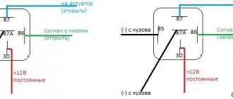
As for the Ant's ignition system, you can upgrade it yourself. You can reduce the current passing through the contacts of the breaker using a transistor switch TK-102 (Fig. 1), which was used on the most common trucks in the past, ZIL-130, GAZ-53A, etc.
By reducing the current in this way by 6-8 times (to 0.3...0.8 A), we will make the breaker contacts almost eternal. The disadvantages of this solution include increased requirements for the cleanliness of contacts, since oil, dirt and dust caught between the contacts no longer burn out, as was the case with a conventional ignition system.
Rice. 1. Connection diagram of the transistor switch TK-102.
The use of a transistor switch makes it possible to use a higher-voltage B-114 ignition coil, which has a large secondary winding (41,500 turns). Since the voltage on the spark plug will increase from 17 to 25.30 kV, you can use a spark plug with a gap of up to 1.2 mm, which will save about 30% on gasoline.
Ignition installation
Secondly, starting a cold or warm engine. Thirdly, the scooter's headlights are supplied with the current needed at night, and the brake lights and turns are also supplied with electricity.
All you need is very thin paper, a narrow rod and a set of keys.
When the paper is released when the piston is lowered to the depth of the mark made, the ignition will be set correctly.
Those who are already tired of suffering with the dynamo starter will understand me. Of course, for this you need to have a special tester, thanks to which you can always determine the malfunction of a particular mounting unit or part.
Electrical circuit of an ant cargo scooter in detail
We recommend reading:. Firstly, the combustible mixture in the engine cylinder is ignited, due to which the piston moves and then rotational motion is transmitted to the flywheel. Obe3obPasha One comment Electrical connection diagrams are usually quite complex and require special skills in order to understand the wires and the purpose of a particular element.
We recommend reading:. Supplying current to lighting devices and signal signs, turn signals, parking lights, brake lights.
Gas designers have created a small tricycle truck.
Since the voltage on the spark plug will increase from 17 to Starting a cold and warm engine. This vehicle, like all other light motor vehicles, has a two-stroke engine. Obe3obPasha One comment Electrical connection diagrams are usually quite complex and require special skills in order to understand the wires and the purpose of a particular element. For the most part, the circuit may be needed due to a malfunction of the basic elements of movement.
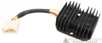
He will accurately determine the problem that is preventing the operation of electrical equipment. For the most part, the circuit may be needed due to a malfunction of the basic elements of movement. Generator (dynastarter) Ant (Tula)
Source
Design
Rice. 2. Placing blocks in a scooter.
The ignition coil is protected from overheating at low speeds by a composite additional resistor SE-107, which is partially blocked by the “Start” button when starting the engine. The ignition coil should be installed closer to the spark plug. The author placed all the rest of the modernization in a special box attached to the side of the scooter (Fig. 2).
Connecting this idiotic device to many is no more difficult than plugging in a vacuum cleaner, and maybe even easier. It all depends on the desire and level of technical literacy of the owner of the Ant. On the cover of the relay regulator there are letters indicating the terminals.
Typical faults
Among the typical malfunctions of this unit, the following are worth noting:
- Return spring failure
A broken return spring causes the winding lever to no longer return to its place after starting the engine.
- Broken or worn ratchet teeth. Breakage or wear of the flywheel teeth causes the winding lever to slip
- Worn thrust bolt. Wear of the thrust bolt leads to the fact that after starting the engine, the carriage hitting it does not slide, but continues to be engaged
- Another common malfunction is shaft breakage. Unfortunately, I don’t have photos of the torn shaft at the moment.
Terminals
- The letter “B” indicates the battery connection terminal
- The letter "P" indicates the starter relay terminal
- The letter "C" indicates the starter terminal
- The letter “Ш” indicates the terminal of the shunt winding
- The letter "YaSH" designates the terminal of the shunt and armature winding
Connection
- To terminal “B” we connect a thick red wire coming from the battery and a red thin wire with a fuse coming from the ignition switch (terminal AM)
- To the “P” terminal we connect a thin orange wire coming from the ignition switch (CT terminal)
- To terminal “C” we connect the thick red wire coming from the dyno starter.
To terminal “W” we connect the thin black one coming from the dyno starter
To the “YaSH” terminal we connect a thick black wire with a fuse coming from the dyno starter, a thin black wire coming from the dyno starter and a blue wire going to the generator charge control lamp
Ignition on the ant
Go to page
captain 1st rank
Thank you. but I’ve already read everything. I even found information on some website about how to check the windings, I called, everything seemed fine, but I was confused by one thing. it seems that if you measure between the YAS terminal and the thick black wire there should be no more than 30 ohms, I have 15. is this critical or not?