The gearbox of the T-200M scooter is a complex unit. And many of our readers are perplexed by the question: how to properly disassemble and reassemble it?
To know this, information only about the assembly sequence and tools is not enough; you need to familiarize yourself in detail with the box, with the operation of its parts and mechanisms. At the request of the editors, engineers V. Kamerilov and L. Boyarnikov talk about the T-200M box.
When starting to talk about the device, I would like readers to carefully read this table. Later, during assembly, it will provide you with a service.
The gearbox consists of two shafts, four pairs of gears and a gear shift mechanism.
Rice. 1. Internal arrangement of shafts and gears in the gearbox
The primary shaft 1 (Fig. 1) of the gearbox rests on two ball bearings 2 and 7, pressed into the holes of the left and right halves of the crankcase. It has a through hole through which the clutch rods pass. Gear 3 of the first gear is made integral with the shaft. Gear 4 of the second gear and gear 6 of the fourth gear rotate freely on the input shaft. These gears are engaged using the movable gear 5 of the third gear, which moves on the splines of the input shaft.
The secondary shaft 9 of the gearbox is mounted on 14 roller and 8 ball bearings, pressed into the crankcase holes. Gear 13 of the first gear and gear 11 of the third rotate freely on the secondary shaft. Gear 10 of fourth gear is stationary. It is secured to the shaft using a press fit.
Gear 12 of the second gear, moving on the shaft splines, alternates between first and third gears.
The transmissions are included in this sequence.
Neutral gear, in which the secondary shaft does not rotate, will be engaged when gears 5 and 12 are in the middle position and their cams do not engage with the cams of adjacent gears. When the clutch mechanism is engaged, the rotation of the gearbox input shaft is transmitted through gear 3 to gear 13.
Rice. 2. Gear shift diagram: a - first, b - second; c - third; g - fourth
The first gear is engaged at the moment when the cams of gear 12, when moving to the left along the splines of the secondary shaft, engage with the cams of gear 13. In this case, gear 5 is in the neutral position (Fig. 2, a).
The second gear (see Fig. 2,b) is obtained by moving the movable gear 5 (see Fig. 1) to the left along the splines of the input shaft. Its cams engage with the cams of gear 4, which is in constant mesh with gear 12, and the latter moves to the middle (neutral) position. In this case, the force from the primary shaft to the secondary one will be transmitted through gears 4 and 12.
The third gear will be engaged after the secondary shaft gear 12 moves to the right, when its cams engage with the cams of gear 11. At the same time, gear 5 is moved to the neutral position. Rotation is transmitted through gears 5 and 11 (see Fig. 2, c).
When gear 5 moves to the right until it engages with the cams of gear 6, fourth gear is engaged (see Fig. 2, d). Thus, rotation from the primary shaft to the secondary shaft is transmitted through a pair of gears 6 and 10. The movable gear 12 of the secondary shaft is at this time in a neutral position.
Rice. 3. Gear shift mechanism
All these switchings are carried out using a special mechanism (Fig. 3). Activation occurs sequentially by pressing the rear shoulder of the two-arm shift lever. The lever rotates around its axis and carries with it a rod, which turns shift roller 1.
On the roller 1, a crank 3 with a pawl 4 having two protrusions is installed on the splines. A gear sector 7 with a ratchet, connected to the shift drum 9, and a return spring 6 are freely mounted on it. The shift drum has two shaped grooves on its surface. It is fitted with shift forks 10 and 11, which fit into the annular grooves of the movable gears of the primary and secondary shafts.
Thus, when the shaft is turned, the movement is transmitted to the crank with the pawl. One of the protrusions of the pawl fits into the corresponding cavity of the sector ratchet, which turns the shift drum. The drum, in turn, causes the shift forks to move axially, which turn the movable gears on the shafts on or off.
To hold the shift drum in a specific position, a locking device is used. It consists of a locking disk 12, a latch 13 with a roller and a spring 2 that presses the latch to the disk.
When assembling the gearbox, you will need a drift made of soft non-ferrous metal or wood to press in the bearings and input shaft and a screwdriver to check the rotation of the gears and the tightening of the screws holding the crankcase halves together.
At the time of assembly, the gears and shift mechanism should be positioned as if they were in fourth gear.
First you need to press the bearings and support bushings into the crankcase. Only after this can you proceed directly to assembling the box itself.
In the left half of the crankcase, into the ball bearing 2 (see Fig. 1), the input shaft assembly with gear 4 is inserted with light blows of a drift. At the same time, gear 13 of the first gear of the secondary shaft should be inserted into the crankcase, engaging it with gear 3.
Then you need to assemble the gear shift drum 9 (see Fig. 3) with shift forks 11 and 10 and the locking disk 12. Insert gear 5 into the fork 11 for shifting the second and fourth gears (see Fig. 1), and into the fork 10 ( see Fig. 3) shifting first and third gears - gear
12 (see Fig. 1).
After this, the shift drum together with the gears must be inserted into the support sleeve of the left half of the crankcase and at the same time pass the input shaft through gear 5.
13 and 12 in the roller bearing of the secondary shaft. Finally, gear 6 is put on the input shaft.
After the work has been done, by rotating the secondary shaft with a screwdriver inserted into the end groove, check the operation of the gears. They should rotate without jamming.
Before installing gear shift roller 1 (see Fig. 3), you must do the following: put crank 3 assembled with pawl 4, roller return spring 2, gear shift disc lock roller 13 onto the shift roller.
Now, when inserting the roller into the left half of the crankcase, you need to pay attention to the fact that the locking roller enters the recess of the shift drum disk in such a position that the fork 11 engages gear 5 (see Fig. 1) with the end cams with gear 6.
Roller return spring 2 (see Fig. 3) must be inserted with one end into the groove in the crankcase, and the other end rested against the lever of the lock roller 13.
Next, we put sector 1 on the roller and make sure that the first right tooth of the sector engages with the shift drum gear. Only now we put the pawl return spring on the switching sector and separate the ends of the spring to connect with the finger on which the pawl sits.
Before connecting the left half of the crankcase to the right, it is necessary to place a gasket soaked in bakelite varnish or autosol between them, and put support washers 8 and 5 on the shift drum and shift shaft.
The carter is connected by lightly tapping its right half. In this case, you should pay attention to the fact that the pawl lock passes between the ends of the return spring and fixes it. Place washers under the tightening screws and tighten them evenly with a screwdriver.
V. KAMERILOV, L. BOYARNIKOV, engineers
Just a couple of months ago, an old client asked to overhaul the engine of his Ant for the season. He is not greedy for money - he promised to buy everything needed for repairs. We agreed, the client brought it for repairs. The piston, crankshaft, motor chain and almost all bearings were worn out.
The customer insisted on purchasing a new crankshaft. They are now in abundance in any store - I don’t want to take them, but their quality is still good... I resisted for a long time and in the end the client found a used engine from which I pulled the crankshaft. Of course, it was slightly worn out, but the bearing of the lower head of the connecting rod was intact and intact, and we didn’t need anything more.
Photo report: Assembly of the gearbox (box) of the “Ant” scooter
After completely disassembling the engine of the Ant scooter, many, especially beginners, have difficulty reassembling the gearbox, and this is not surprising.
There is very little reference information, there are too many “ant” experts, the matter is further complicated by the fact that there are no marks on the gearbox parts that greatly simplify the work on the correct orientation of the gearbox parts relative to each other. In fact, everything is not as complicated as it might seem at first glance...
The gearbox, after disassembling the engine and troubleshooting the parts, turned out to be in very good condition; only one gear of the first gear had to be replaced (extreme wear of the bushing and, as a consequence, increased backlash of the gear on the shaft) and all the bearings (due to severe wear). All other gearbox parts were checked for wear and so on without any problems. Complete disassembly of the “ant” engine is described in detail in the article: Photo report: Disassembling the engine of the “Ant” scooter
Before assembling the gearbox, we carefully wash all the parts from dirt, pay special attention to the engine crankcase and the condition of the threaded connections, buy a new set of oil seals and gaskets (preferably made of paronite). The general principles of engine crankcase repair are described in detail in the article: Photo report: Repairing a scooter engine crankcase
And so, the right half of the crankcase is completely washed, laid on wooden blocks and is completely ready for the introduction of our gearbox into it.
We insert the retaining ring into the mounting hole of the secondary shaft bearing.
Using a mandrel, install the bearings into their mounting holes. Don't forget to place a special washer under the input shaft bearing.
We check the performance of the copier, for this: we press on it with a screwdriver or a finger and release it - several times, there should be no jamming or excessive play in its operation, the working surface should be strictly in the form of a cone (not “slicked”).
We carefully inspect the teeth of the “pawl” of the gear shift mechanism; there should be no cracks, chips, or wear. The teeth should be sharp (not “slick”).
In the same way, we inspect the teeth of the crescent of the gear shift mechanism.
We assemble the gearshift shaft and install the return spring.
We install the gearshift shaft into the engine crankcase.
We install the secondary shaft in its place.
We put the fourth gear gear in its place.
Apply any grease to the thrust washer of the tracing shaft (marked with an arrow) and place it on the mounting hole of the tracing shaft.
We unfold the crescent of the gear shift mechanism so that its last tooth (marked by an arrow) engages with the gear of the copier shaft.
We take the copy shaft and carefully inspect the forks of the gear shift mechanism, they should not show signs of excessive wear and signs of overheating (blue), wear on the working surface of the forks should not be more than 0.5 mm. You should also check the ease of movement of the forks on the shaft and the play, which should not be excessive.
These small abrasions on the forks are considered quite normal for this engine.
We take the copy shaft in our hand (with the daisy pointing towards us) and turn the forks of the gear shift mechanism all the way to the right (clockwise), the forks should take the position as in the photo.
We put the gearbox gears on the forks; the first and third gear gears (large) are placed on the long fork; the second and fourth gear gears (small) are placed on the short fork.
We install the copy shaft assembly with gears in place, while carefully ensuring that it is the last tooth of the crescent of the gear shift mechanism that engages with the gear of the copy shaft (as in the photo). If the crescent meshes with the gear with another tooth, then the gearbox will not work correctly in this case.
Reinstall the input shaft.
We put the first gear gear on the secondary shaft and swing it; if large play is detected, we replace the gear with a new one.
We install the copy shaft clamp along with the spring on the gear shift mechanism shaft.
After assembling the gearbox, we must check its functionality and prepare the engine for final assembly. The final assembly of the engine is described in detail in the article: Repairing the Ant scooter engine
Source
Photo report: Repair and assembly of the gearbox of the Ant, Tula scooter
An old acquaintance approached me with a request to repair the gearbox of his Tula or Ant - I still didn’t understand. The engine was half disassembled: without a cylinder and clutch. To be honest, I had nothing to do with the “Tula” in terms of repairs; I only repaired the “Ants” all the time. I only heard that the “Tula” shifts gears like a regular motorcycle, and not like the “Ant”
As for the problems with this particular checkpoint, I can only guess what problems it had. The client himself did not fully understand everything: either the third and second gears were knocked out, or these gears were slipping - I still didn’t understand... However, this is not the point. Another thing is important: the client, knowing my dislike for “left-handed” spare parts, brought a bunch of used parts in addition to the engine, which actually could not but make me happy and reassuring about the expected result of my intervention in this gearbox
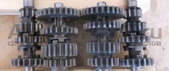
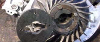
From all the heaps of used spare parts, I managed to assemble two fully functional gearboxes, which, by the way, have some differences. That gearbox (on the right) which has a wider third gear intermediate gear is clearly not “Muravyovskaya” - I’ll assume that it’s either from Tula or from the old “Muravyov” or I don’t understand something anymore...
In that pile there were two serviceable copying shafts with different “daisies”. The left shaft, judging by the “daisy”, is clearly not “Ant”. I'm guessing he's from Tula. Again, I could be wrong, since I always repaired only “Ants” and I have never seen a copy shaft with such a “daisy” in them
And so I thought and this way: the “Tula” gearbox does not give any advantages and it is not very familiar to me in terms of repairs, and I decided to stop at the “Muravyinnaya” and, as for me, the gear shift algorithm of the “Ant” is much more convenient
At what speed is the ant's gearbox assembled? Ant scooter repair
As for the problems with this particular checkpoint, I can only guess what problems it had. The client himself did not fully understand everything: either the third and second gears were knocked out, or these gears were slipping - I still didn’t understand... However, this is not the point. Another thing is important: the client, knowing my dislike for “left-handed” spare parts, brought a bunch of used parts in addition to the engine, which actually could not but make me happy and reassuring about the expected result of my intervention in this gearbox
From all the heaps of used spare parts, I managed to assemble two fully functional gearboxes, which, by the way, have some differences. That gearbox (on the right) which has a wider third gear intermediate gear is clearly not “Muravyovskaya” - I’ll assume that it’s either from Tula or from the old “Muravyov” or I don’t understand something anymore...
In that pile there were two serviceable copying shafts with different “daisies”. The left shaft, judging by the “daisy”, is clearly not “Ant”. I'm guessing he's from Tula. Again, I could be wrong, since I always repaired only “Ants” and I have never seen a copy shaft with such a “daisy” in them
And so I thought and this way: the “Tula” gearbox does not give any advantages and it is not very familiar to me in terms of repairs, and I decided to stop at the “Muravyinnaya” and, as for me, the gear shift algorithm of the “Ant” is much more convenient
Ant scooter gearbox. Ant scooter repair
An old acquaintance approached me with a request to repair the gearbox of his Tula or Ant - I still didn’t understand.
The engine was half disassembled: without a cylinder and clutch. To be honest, I had nothing to do with the “Tula” in terms of repairs; I only repaired the “Ants” all the time. I only heard that the Tula shifts gears like a regular motorcycle, and not like the Ant. As for the problems with this particular gearbox, I can only guess what problems it had. The client himself did not fully understand everything: either the third and second gears were knocked out, or these gears were slipping - I still didn’t understand... However, this is not the point. Another thing is important: the client, knowing my dislike for “left-handed” spare parts, brought a bunch of used parts in addition to the engine, which actually could not but make me happy and reassuring about the expected result of my intervention in this gearbox
From all the heaps of used spare parts, I managed to assemble two fully functional gearboxes, which, by the way, have some differences. That gearbox (on the right) which has a wider third gear intermediate gear is clearly not “Muravyovskaya” - I’ll assume that it’s either from Tula or from the old “Muravyov” or I don’t understand something anymore...
In that pile there were two serviceable copying shafts with different “daisies”. The left shaft, judging by the “daisy”, is clearly not “Ant”. I'm guessing he's from Tula. Again, I could be wrong, since I always repaired only “Ants” and I have never seen a copy shaft with such a “daisy” in them
And so I thought and this way: the “Tula” gearbox does not give any advantages and it is not very familiar to me in terms of repairs, and I decided to stop at the “Muravyinnaya” and, as for me, the gear shift algorithm of the “Ant” is much more convenient
Malfunctions
Due to the fact that when starting the engine, the force from the kickstarter is directly transmitted to the first gear gear, the bushing with which the gear rests on the input shaft wears out and wears out so that the gear simply begins to dangle on the shaft
- Before assembly, we put the first gear gear in its place and try to swing it. If the gear is loose, replace it with a new one, or, if you have experience in this area, change only the bushing and leave the gear
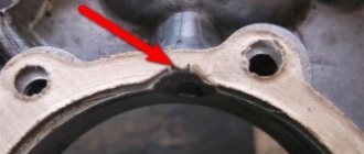
- The second typical malfunction is due to the fact that the roller that fixes the copy shaft does not always work exactly on the “daisy”, but often jumps off it and instead of the roller, the “daisy” is fixed by the locking bar, as in my case. Such a malfunction leads to the fact that the gears begin to knock out, fail to engage or jump over one
Notice how the contact with the “chamomile” erased the bar and cut off one tendril of the cotter pin
- This malfunction can be eliminated very easily and simply: place the retainer bar along with its spring on the gearshift shaft and insert the shaft into the crankcase. Then insert the copy shaft there and turn it several times and see where the roller runs.
- If the roller does not run along the “daisy”, use pliers to bend the clamp bar in the desired direction so that the roller runs strictly along the “daisy” of the copy shaft
Correct roller position
All other malfunctions that this gearbox suffers from are typical for Soviet-made motorcycle gearboxes and consist of wear on the working edges of the cam clutches, gear teeth and gear shift forks
For clarity, I dug out for you from a pile of rubbish the input shaft with truly extreme wear on the teeth of the first gear drive gear. Its tooth wear is about 1mm. It seems that the only thing they were doing with this scooter was that they were “pulling GAZelles”... Such wear on the gears is critical and the shaft is not subject to further use
No matter how many times I went through TMZ engines, I never came across gears with worn cam couplings, and I went through a couple of cars of them, if not more... I dare to suggest that wear on cam couplings is not a typical problem with TMZ engines, unlike Izh, Zid and other engines
The gear claw couplings should be in approximately this condition. Unfortunately, I was never able to find gears with worn couplings even in a pile of rubbish. So there's nothing to show
All gearboxes, including this one, suffer from wear on the working surfaces of the forks. If the wear is no more than about.5mm, then this is quite acceptable
Assembly
We look inside the right half of the crankcase for a copier on which the pawl of the gear shift mechanism moves, and with several clicks we check its functionality
We take the copy shaft in our hand so that its “daisy” looks at you and turn the gear shift forks clockwise until it stops
Without changing the position of the gearshift forks, we assemble the gearbox and insert the forks into it along with the copy shaft in the order shown in the picture
Without disturbing the position of the parts, we install the gearbox assembly with the tracking shaft in the right half of the crankcase and install the gear shift shaft there along with the locking bar. After installing the retainer bar, do not forget to insert its return spring into a special slot inside the crankcase
The procedure for installing a gearbox, with the necessary skill, is very easy and quick. If you are unable to install the gearbox this way, disassemble it and install the parts separately
To be extra sure that the copy shaft did not accidentally turn during assembly, turn it as far as possible clockwise
We install a sector of the gear shift mechanism on the gear shift shaft, making sure that it is its last tooth that engages with the gear of the copy shaft, and not some other one. After installing the sector, we put a return spring on the gearshift shaft
And we enjoy the impeccable performance of the manually assembled gearbox.
Just a couple of months ago, an old client asked to overhaul the engine of his Ant for the season. He is not greedy for money - he promised to buy everything needed for repairs. We agreed, the client brought it for repairs. The piston, crankshaft, motor chain and almost all bearings were worn out.
The customer insisted on purchasing a new crankshaft. They are now in abundance in any store - I don’t want to take them, but their quality is still good... I resisted for a long time and in the end the client found a used engine from which I pulled the crankshaft. Of course, it was slightly worn out, but the bearing of the lower head of the connecting rod was intact and intact, and we didn’t need anything more.
Photo report: Repair and assembly of the gearbox of the Ant, Tula scooter
An old acquaintance approached me with a request to repair the gearbox of his Tula or Ant - I still didn’t understand. The engine was half disassembled: without a cylinder and clutch. To be honest, I had nothing to do with the “Tula” in terms of repairs; I only repaired the “Ants” all the time. I only heard that the “Tula” shifts gears like a regular motorcycle, and not like the “Ant”
As for the problems with this particular checkpoint, I can only guess what problems it had. The client himself did not fully understand everything: either the third and second gears were knocked out, or these gears were slipping - I still didn’t understand... However, this is not the point. Another thing is important: the client, knowing my dislike for “left-handed” spare parts, brought a bunch of used parts in addition to the engine, which actually could not but make me happy and reassuring about the expected result of my intervention in this gearbox
From all the heaps of used spare parts, I managed to assemble two fully functional gearboxes, which, by the way, have some differences. That gearbox (on the right) which has a wider third gear intermediate gear is clearly not “Muravyovskaya” - I’ll assume that it’s either from Tula or from the old “Muravyov” or I don’t understand something anymore...
In that pile there were two serviceable copying shafts with different “daisies”. The left shaft, judging by the “daisy”, is clearly not “Ant”. I'm guessing he's from Tula. Again, I could be wrong, since I always repaired only “Ants” and I have never seen a copy shaft with such a “daisy” in them
And so I thought and this way: the “Tula” gearbox does not give any advantages and it is not very familiar to me in terms of repairs, and I decided to stop at the “Muravyinnaya” and, as for me, the gear shift algorithm of the “Ant” is much more convenient
Build errors
In most cases, the right main bearing of the crankshaft fails due to an assembly error almost in the first season after repair. The engine that we are now repairing is no exception. The bearing has practically crumbled and in any case needs to be replaced with a new one.
The mistake is that when installing the flange on which the dynostarter stator is attached, the oil channel through which lubricant flows to the main bearing and oil seal is sealed.
To ensure that the main bearing lasts at least several seasons, cut the gasket under the flange a little along the contour of the oil channel and when you put the flange in place, do not smear anything with sealant there.
Assembly
I bought this main bearing. It seems to be our production. There are Chinese analogues in stores - they are more expensive, but I don’t know what their quality is... I try to buy something that may not be of such super-duper quality, but at least one that has been proven over the years.
The quality of production is such that there is essentially nothing to complain about. The price is quite reasonable - 350 rubles.
We press the inner race of the main bearing onto the right crankshaft journal. External - screw the stator flange of the dynostarter and press it into the crankcase until it rests against the flange.
We install the oil seal, retaining ring and main bearing into the left half of the crankcase. I'm installing a new main bearing. It is closed, but it doesn’t matter: we open it, wash out the factory grease and install it in the crankcase.
Lubricate all bearings and working edges of oil seals with clean engine oil. And very carefully, so as not to accidentally wrap the edge of the oil seal - insert the crankshaft into the left half of the crankcase, and knock out the crankcase guides by 5-6mm.
We degrease the crankcase connector, install a new gasket and install the second half of the crankcase.
Tighten the bolts and immediately so that nothing gets into the crankcase -. I'm installing a new piston, cylinder head and reed valve body. The piston one, like everything else, is of no particular origin - most likely Rostov, but clearly not Chinese. I didn’t want to get involved with this counterfeit, but the owner didn’t want to wait until they bore the cylinder and put a liner in the cylinder head and insisted on buying it. You see the prices for spare parts - it’s up to you to decide whether to contact this new product or not.
We install the second main bearing into the crankcase and secure it with a retaining ring.
It's no secret that the engineers of the Tula plant have created equipment with which the average owner has to feel like a mechanic. To this day, having found another problem, Ant’s owner has to pick up a tool, remembering the would-be engineers. One of the main problems is the engine of the Ant scooter, which is repaired in most cases of breakdowns.
Device and technical parameters
The design of the Ant scooter was quite simple and consisted of the following main parts:
- engine;
- frame;
- transmission and suspension;
- electrical equipment;
- brake system;
- body.
Such a simple design of the Ant 2M 01 scooter and its wide unification with the two-wheeled Tulitsa (Tula) model allowed the owners to carry out repairs themselves.
The TMZ Ant motor scooter had the following technical characteristics and operational parameters (data for modification of the Ant 2M motor scooter are given in parentheses):
- Drive – 3x2.
- Load capacity – 0.25 t (0.28 t).
- Engine:
- type – petrol two-stroke,
- ignition – electronic;
- number of cylinders – 1,
- volume – 0.20 l,
- cooling option – forced air,
- power – 11.0 l. With. (12.5 hp),
- carburetor - K-36G,
- fuel – a mixture of gasoline and oil (1/33).
Operation Y or how I registered the Ant scooter — DRIVE2
Two months ago I bought a scooter. I decided to register it, passed the inspection, signed up for the MTPL policy, received the policy a month later, and now the time has come for its registration. It all took three days and a little patience.
I went to the MREO station on a scooter, wrote a statement, went through an inspection, took a ticket (the time was not right). I went home, I think after lunch. I went to the inspector and asked how much the state duty would cost and whether it was possible to register. Inspector's answer Yes 2800.
I arrived at 9 and took a ticket. It’s 10-30. The time has come, I go to the window and hand over the documents. And the inspector (another) issues a refusal to register with the wording 605 of the order, lack of documents for ownership. I give him my application for the head of the MREO. He doesn’t have the plant’s seal here. I pick up the docks and go to the head of the MREO, he sends it to the deputy. The deputy, having looked at everything, calls the inspector and says that he should read the order and some point well, and supposedly I (motorcycle) will drive up. I’ll go to the inspector. He accepted the documents, made copies, and said I’ll consult with the boss and call back. I called and made an appointment for tomorrow.
In the evening he calls and says he needs a purchase and sale agreement. OK
In the morning I received a letter from the manufacturer’s plant about my request to issue a title. The content is as follows: Documents on the scooter were archived and destroyed three years later. The production of motorcycles was discontinued in 1995. Signature. Tarpan.
I immediately went to the head of the MREO. He said we’ll figure it out, they fumbled for 1.5 hours and gave the go-ahead. After another 1.5 hours I had a brand new title in my hands with the first owner, STS, and license plates.
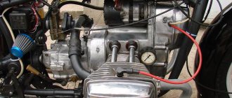
Dynastarter
However, it is not only the engine that can make a motorcyclist clearly see all the components of his motorcycle. The most common problem is a problem with the dynastarter.
. The engineers of the Tula plant installed it in Muravya, instead of a conventional alternating current generator.
Why is it so important? If you notice a red light on the instrument panel while the moped is running, it means you are running out of charge. This happens because the generator is not producing alternating current. To begin with, in such a situation, it is necessary to check the integrity of the wires connected to the dynastarter and the relay regulator. If everything is in order, then the problem lies directly in the dynastarter. There may be three main causes of problems:
- difficulty in rotor operation (dirt getting into the collector or dust accumulation);
- freezing or wear of brushes;
- violation of the integrity of electrical equipment.
Since in most cases the operation of the dynastarter is difficult due to contamination of the collector, it is worth carrying out a simple disassembly according to the instructions described in the moped operating book. The main rules when working are neatness and cleanliness. After disassembly, be sure to thoroughly rinse all parts in gasoline and lubricate the rubbing parts, and under no circumstances throw away the parts.
Ant scooter device
During the Soviet years, this bloodsucker Ant was bought only for its body. Since nothing like this was produced in the USSR in those years. And people needed to either go to the garden or feed the farm, so they took him. The body in the Ant is really good; you can easily load 10 bags of mixed feed, 500 kilograms of coal or half a cubic meter of firewood and it will safely trample all this junk home. On the two-seater version, the body was significantly smaller and moved far back, causing the overloaded scooter to tip over backwards on bumps. But on the two-seater version it was possible to ride together
Motor scooter Ant: technical characteristics, modernization
The Ant scooter was produced at the Tula Machine-Building Plant from 1959 to 1995. Its modification, or as they say now, restyling, was carried out in 1983 and the updated version received the designation Ant 2M 01. The longevity of this unusual three-wheeled vehicle was brought, first of all, by positive qualities, among which it is necessary to highlight:
The TMZ Ant scooter was the first cargo model of motorcycle equipment mass-produced in the USSR. The presence of a cargo platform allowing it to transport 250 kg of cargo at a speed of 60 km/h made the Ant very popular. It is enough to note the areas in which it was used:
For various modifications of the TMZ Ant scooter, four body options were used:
The most significant drawback is the lack of any comfort for the driver, who was forced to spend almost the entire working day behind the wheel of a scooter. It was especially difficult to work in winter, since, unlike two-wheeled mopeds, scooters and motorcycles, the Ant cargo scooter was used at state-owned enterprises even in winter.
Device and technical parameters
The design of the Ant scooter was quite simple and consisted of the following main parts:
Such a simple design of the Ant 2M 01 scooter and its wide unification with the two-wheeled Tulitsa (Tula) model allowed the owners to carry out repairs themselves.
The TMZ Ant motor scooter had the following technical characteristics and operational parameters (data for modification of the Ant 2M motor scooter are given in parentheses):
The main disadvantages of a scooter and its modernization
The Ant scooter, like any technology, in addition to its positive qualities, also had disadvantages. At the same time, the existing shortcomings could be attributed both to structural ones, originally inherent in the device, and to operational ones, arising during the operation of the equipment.
According to reviews from owners, structural defects that required rework or the most frequent repair of a particular unit include:
The most common operational deficiencies are:
Very often, the owners, having gained experience in operating the Ant scooter, carried out modernization. But before starting to implement the changes, the following issues were resolved:
After receiving positive answers to these questions, work on changes was carried out. Tuning the Ant scooter, which made it possible to give it additional properties, boiled down to the following basic alterations:
Engine assembly
Unlike a dynastarter, repairing an Ant scooter engine with your own hands is difficult to do according to the operating book. Therefore, it is worth seeking the advice of experienced motorcycle owners. Most often, the engine has to be disassembled when there are problems with the clutch mechanisms, the operation of the gearbox, as well as wear on the crankshaft, bearings or oil seals. The most important rule is not to be afraid to disassemble the engine yourself. Using these instructions, disassembling and assembling the engine of the Ant scooter will not be difficult.
So, the procedure for disassembling the engine:
You can see how to assemble an Ant scooter engine in more detail in the visual video at the end of the article. The essence of assembly is in the reverse order, but it is important to tighten the parts with a certain force and synchronize the parts with the marks. Under no circumstances should you assemble an engine without detailed instructions written by the manufacturer.
With frequent breakdowns, owners think about what engine can be installed on the Ant scooter. Instead of the original motor, you can use Chinese analog motors
. Since the Ant has many copies in Asian countries, replacing the engine can be a great option to save money in case of irreversible damage. True, you will have to make the fastenings yourself and, in some cases, remake the bridge for the left-hand arrangement of the chain. This is not very difficult, considering that the Tula plant provided for the possibility of rearranging the bridge.
Electrical circuit of the Ant scooter
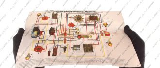
Ant scooters are cargo versions of the Soviet retro scooters Tula, Tulitsa and Tourist. Despite the huge number of modifications, the electrical circuit of the Ant scooter fits almost all mopeds of the Tula Machine-Building Plant.
In this publication we will look at the wiring diagrams for Ant scooters, models TG-200 and 2M, as well as their modifications.
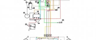
Electrical circuit of the motor scooter Ant TG 200
The Ant TG 200 is based on its passenger car predecessor, the Tula T-200. The wiring diagram does not have complex components and is suitable for analogues of the Ant TG 200 scooter: TG-200F, TG-200I, TGA 200, TGA 200-01.
Download the electrical diagram of the Ant TG 200 scooter:
Ant 4X4 complete rework on DRIVE2.RU
It all started with a motor scooter, , ant, . Actually, the name stuck with it. I dragged it, started it, no brakes, no 1.2 gears... no wonder, it stood for about twenty years in the garden under an apple tree. I rode it like that for a season, in the winter I decided rebuild the engine and off we go... During the rebuilding process, the engine underwent a number of upgrades (received a fundamentally new bearing on the secondary shaft; the crankshaft was rebuilt to fit a new type of connecting rod, balanced; the engine received a new type of piston.) These alterations required some modifications, but more on that in BZ records. After reassembling the engines, I put it in place, started it, revved it up and decided to continue working. My gaze fell on the chassis... I wanted to make a four-wheeled ant. And away I went... After I made the front suspension, I thought: isn’t the engine a bit weak? I decided to replace it with an engine from the M 72, 1952 (I still had it from an unfinished project), it also went through a number of forced alterations due to its poor condition. I cut off the mount of the standard engine. I installed the engine from the emka, looked at the rear suspension and decided: it doesn’t work! It needs to be redone. And coordinated alterations began...
Source