Basic faults
- Mechanical, caused by natural wear, combustion of windings, destruction of contact groups
- Structural, due to design features
- Malfunctions of the relay regulator that lead to dyno starter failure
The most unpleasant malfunctions are related to mechanics: combustion of windings, interturn short circuit, wear or destruction of the commutator. Other mechanical faults such as wear or sticking of brushes, contamination of the commutator, breakage or oxidation of wires and terminals can be eliminated quite easily.
Diagnostics
The first sign that something has burned out, shorted or broken in the dyno starter or relay regulator is when, out of the blue, right in the middle of the road, your battery charge control lamp comes on.
If this happens to you, then the first thing you need to do is inspect the wires going from the dyno starter to the relay regulator, check the fuse, remove the cover from the relay regulator and at least visually determine the integrity of its elements, remove the rotor and see what’s wrong with the brushes and collector and if nothing suspicious is found there, turn to a very competent electrician for help.
You can try to identify the fault yourself, and within the framework of this article it would be possible to describe all the stages of testing, including the author’s developments, but none of you will do this. In the best case, poke it a couple of times with the tester and you’ll give up on this matter, or even end up using a magnet instead of a dynostarter.
The second sure sign that your dyno starter is in perfect order, but it’s just time to service it, is when, at idle and low engine speeds, the charge warning lamp first begins to blink slightly, then begins to burn more steadily and after a while begins to burn at full intensity throughout engine speed range.
In both the first and second cases, without disassembling the dynostarter, little can be learned about its condition, so if there are any complaints about its operation, we roll up our sleeves, prepare the tool and get started.
Inappropriate installation option
What carburetors are suitable and what is better to install? We will have to disappoint those who plan to use available models from Oka or Zhiguli during the conversion. All car modifications are out of play in this case. There are several reasons:
- The vacuum in the intake tract of a motorcycle differs from the parameters typical for car engines. Because of this, correct adjustment of the carburetor on a motorcycle becomes almost impossible.
- The selection is carried out not simply by working volume, but by the number of aspirations per unit of time. Aspiration can be roughly calculated by multiplying the engine displacement by the maximum speed.
- Car models pose a danger if the motorcycle falls because fuel can splash out and ignite.
Automobile carburetors are not suitable for conversion!
So the idea of using parts from Oka or other automotive equipment will have to be abandoned.
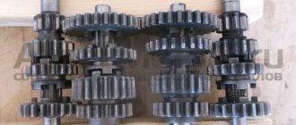
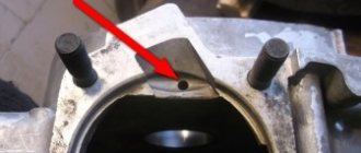
Disassembly
We remove everything that interferes with the removal of the rotor, hold the rotor by the fan with your hand and unscrew the nut
A good owner should have a washer and a lock under the nut. The bad one won’t even have a nut...
Remove the rotor from the crankshaft. The rotor can be removed either with a factory puller or with a homemade one - it makes no difference.
First of all, we inspect the rotor commutator and brushes. The commutator must not show any wear or damage. For example, this collector is just dirty and after we wash it, the dynostarter will start working again.
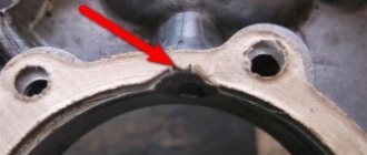
And some deer broke out the lamellas of this collector. Such a rotor will be difficult to help and easier to throw away. To prevent this from happening to your rotor, select bolts for the coupling for the magnet and the fan of the appropriate length, and do not put everything you have on hand there...
This collector was pulled up by something, the lamellas were shorted together and the dynostarter died. If you find a good turner, he will be able to sharpen the scuffs and the rotor’s performance will be restored.
There are situations when the rotor is dropped or the windings are hit. You understand that damage to the power windings will not improve the reliability of your scooter’s power supply system, so handle such devices very carefully and use pullers, and do not knock them down like tractor drivers with a hammer.
On this rotor, someone smacked the windings with relish.
Making a long-link fork
When preparing the M-63K motocross motorcycle for competitions, a lot of work is done to adjust and fine-tune the components of the undercarriage.
The largest alterations include the production of a long-link front fork (instead of a telescopic one) and a lightweight stroller with a spring-hydraulic shock absorber. A motorcycle with a long-link front fork is more stable on bumps and turns. The fork parameters can be easily adjusted depending on the route.
rice. 62. Long-lever fork, made on the basis of the fork components of the M-63 motorcycle. 1 — upper bridge, 2 — lower bridge, 3 — fork leg, 4 — extension sleeve, 5 — wheel axle, 6 — fender, 7 — shock absorber, 8 — lever axis, 9 — shock absorber mounting bracket; 10 — swing arm (pendulum), 11 — lugs, 12 — shock absorber mounting lugs
According to the kinematic diagram, lever forks can be divided into pushing (the swing axis of the levers is located behind the wheel axis) and pulling (the swing axis of the levers is located in front of the wheel). Depending on the design of the swing arms, both pulling and pushing forks are divided into long-lever and short-lever. For long-lever forks, the length of the levers is close to the radius of the wheel. The length of the short-lever fork arms is significantly less than the radius of the wheel. An example of a short-lever fork is the fork of the K-750 motorcycle, and a long-lever fork is the front forks of domestic scooters. The vast majority of athletes in our country use pushing long-link forks.
Let's consider the design of a long-lever fork (Fig. 62). Its two feathers are connected by a lower bridge by welding. A rod is pressed into this bridge, onto which the upper bridge is placed when mounting the fork on the frame. Extension bushings are inserted into the lower ends of the stays, to which bushings are welded to accommodate the bearings of the swing arm axles, and in the middle part of the stays under the lower bridge, crane mattes for shock absorbers are welded.
The swing arm is made in the form of a single curved pipe, to which lugs for attaching the axles and lugs for attaching the wheel axle are welded. The shock absorbers are attached through rubber-metal hinges with the upper bushing to the fork leg bracket, and the lower bushing to the ears of the swing arm.
When making a long-lever fork from a unified telescopic fork, they take fork leg pipes, a steering column bridge with a traverse rod, tightening nuts, parts for fastening the fork in the motorcycle frame, and feather tips.
Additionally, it is necessary to manufacture stay extensions, a pendulum, brackets and lugs, shock absorber mounts, pendulum mounting lugs, reinforcing ties, and a pendulum mounting unit. The fork legs can be made from seamless pipes with an outer diameter of 36 mm and a wall thickness of 5-6 mm. When using chromansil pipes, the wall thickness can be reduced. Reinforcing ties are made from a seamless pipe with a diameter of 20-22 mm and a wall thickness of 1-1.5 mm.
Rice. 63 Parts and assemblies of the front fork: a - pendulum with axle mounting inserts, b - shock absorber mounting eye, c - pendulum mounting eye, d - spacer washer between the bearings and the eye, e - bearing mounting cage, f - spacer ring between the bearings, g - development of the shock absorber bracket fastening, h - fastening the extension and clip to the fork leg, / - inserts for baptizing the axle, 2 - welding points, 3 - clip, 4 - extension, 5 - stay
The swing arm (pendulum) is made using a pipe bender from a seamless seamless pipe with a diameter of 32 mm and a wall thickness of 2.5-3 mm. From the tips of the feathers of the M-63 fork, inserts are made for attaching the wheel axle. For this purpose, the tips are turned on a lathe. The machined inserts are pressed into the ends of the pendulum and secured by welding. From steel 20 (Fig. 63) two eyes are made for attaching the pendulum and two ears for attaching the shock absorber, as well as two brackets for attaching the upper bushing of the shock absorber.
There are various options for the pendulum mounting unit. In one version, the pendulum swings on ball bearings No. 202, pressed in two pieces into cages, which are welded to the stay extensions. In another embodiment, the design of the pendulum mounting is simpler. The pendulum swings on rubber-metal bushings, which use shortened rubber silent blocks of the rear pendulum of an Irbit motorcycle, i.e. the unit is designed in the same way as the rear pendulum unit.
The approximate procedure for assembling the fork is as follows: extensions are inserted into the fork stays (if stays from M-63 are used) and secured by welding. Then, bearing races are welded to the extensions (or directly to the stays), if they are made from a whole pipe. The lower and upper bridges are placed on the frame and secured in bearings, and the fork stays are installed. Bushings are inserted into the bearing mounting cage, the holes are placed coaxially using an auxiliary axis, and the stays are secured in the fork bridges. Warming up the feathers with a gas burner, bend them at the base of the lower bridge until the distance between the axis of the pendulum bearing and the axis of the engine mounting is 360 mm (see Fig. 62).
The axle mounting inserts are placed at the ends of the pendulum along with the axle and welded. Then the lugs are installed relative to the front axle. After this, the eyes are attached by welding to the pendulum. A steel half-ring is welded onto the right arm of the pendulum to secure the brake drum. Install and weld the reinforcing ties, and then the shock absorber mounting lugs in place in accordance with the existing shock absorbers. After final assembly, check the average overhang length, which should be 40–60 mm.
Any hydraulic shock absorbers with a stroke of 120-150 mm can be used as shock absorbers for such a fork. You just need to select springs of appropriate stiffness. Good results are obtained by using shock absorbers from Moskvich and Zhiguli cars in combination with springs from an M-63 motorcycle.
Let's consider the manufacture of shock absorbers from the front shock absorbers of the Moskvich car. Automobile shock absorbers are disassembled, the upper part of the piston, to which the spring washers are pressed, is ground on a plate, a rod 177 mm long is remade or remade. After manufacturing, it must be chromed and polished so that it does not corrode. Two upper shock absorber tips are also made (you can use parts of this unit from the M-63 motorcycle) and four crackers, and a spring support washer, used from the M-63 motorcycle suspensions, is welded to the body.
Before installation, the first four or five turns of the spring are machined onto the cone. The machined spring has variable stiffness, as a result of which the suspension works well both on small road irregularities and when jumping.
The upper casing of the homemade suspension is the lower casing of the suspension of the M-63 motorcycle. Lower casings are not installed on the suspensions of sports motorcycles to avoid jamming of the suspension when both casings are crushed. For the lower tip of the shock absorber, rubber-metal bushings are used from the Moskvich car, and for the upper tip, its spring bushing is used. To prevent dirt and small stones from getting between the rod and the oil seal, use plastic film, rubberized nylon and other similar material, which is wound in two or three layers on the assembled suspension and secured with electrical tape.
Shock absorbers from Volga and Zhiguli cars are also used, but they require a composite spring made from one and a half springs of the M-63 motorcycle.
The long-lever front fork should be equipped with a two-cam brake drum from the M-67 motorcycle, which will significantly improve the dynamics of the motorcycle.
Cleaning the collector
Take a small screwdriver and clean out the dirt between the slats. The collector must be cleaned very carefully so as not to scratch the lamellas.
After cleaning, blow the collector with compressed air, wash it with clean gasoline and wipe it dry with a rag. It is best to wash the collector with a brush: wet the brush in clean gasoline and wash it until the dirt is completely removed. When the gasoline has completely evaporated, take a piece of some lint-free cloth, moisten it a little in gasoline and carefully rub the collector with the maximum possible force until it is perfectly clean.
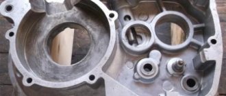
Checking the stator windings
We unscrew the stator mounting bolts, tap it around with a wooden mallet, remove it from the engine, turn it over with the wires towards you, switch the tester to the continuity mode, connect the tester probes to the two rightmost terminals of the windings, if the tester beeps, there is no winding breakage.
We do the same with the remaining two wires: put the tester into dialing mode, connect the tester probes to the ends of the wires, if the tester beeps, there is no winding break.
After checking the windings for breaks, we carry out an additional check of the stator for breakdown of the windings: we switch the tester to the continuity mode, alternately touch the wires with one probe, and touch the stator housing with the second. If the tester does not beep, the windings are not broken. If it beeps or numbers appear on the screen, the windings are broken to ground.
Advantages of a polycarbonate windshield over regular glass
- Polycarbonate glazing is resistant to ultraviolet radiation and temperature changes;
- Such strong glass has a minimum number of stiffeners;
- Polycarbonate perfectly transmits light and glazing, thus providing a full overview;
- The material is not prone to destruction;
- A windshield made of this material is lightweight and does not create excessive loads;
- Monolithic polycarbonate is easily molded when heated and therefore its shape can be any.
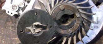
Checking the brushes
We turn the stator over with the brushes facing us, check the brushes for wear: the working surface of the brushes is slightly thinner than the main one, if the working surface on your brushes is worn out, replace such a brush with a new one.
Worn brush
Normal brush
After checking the brushes for wear, we check one by one how the brushes move in the sockets; if the brushes hang up, we sharpen them with a file until they move in the sockets without jamming.
After all that has been done, we install the dyno starter parts in place, adjust the ignition and enjoy the impeccable operation of the electrics of your scooter.