An old acquaintance approached me with a request to repair the gearbox of his Tula or Ant - I still didn’t understand. The engine was half disassembled: without a cylinder and clutch. To be honest, I had nothing to do with the “Tula” in terms of repairs; I only repaired the “Ants” all the time. I only heard that the “Tula” shifts gears like a regular motorcycle, and not like the “Ant”
As for the problems with this particular checkpoint, I can only guess what problems it had. The client himself did not fully understand everything: either the third and second gears were knocked out, or these gears were slipping - I still didn’t understand... However, this is not the point. Another thing is important: the client, knowing my dislike for “left-handed” spare parts, brought a bunch of used parts in addition to the engine, which actually could not but make me happy and reassuring about the expected result of my intervention in this gearbox
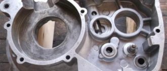
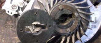
From all the heaps of used spare parts, I managed to assemble two fully functional gearboxes, which, by the way, have some differences. That gearbox (on the right) which has a wider third gear intermediate gear is clearly not “Muravyovskaya” - I’ll assume that it’s either from Tula or from the old “Muravyov” or I don’t understand something anymore...
In that pile there were two serviceable copying shafts with different “daisies”. The left shaft, judging by the “daisy”, is clearly not “Ant”. I'm guessing he's from Tula. Again, I could be wrong, since I always repaired only “Ants” and I have never seen a copy shaft with such a “daisy” in them
And so I thought and this way: the “Tula” gearbox does not give any advantages and it is not very familiar to me in terms of repairs, and I decided to stop at the “Muravyinnaya” and, as for me, the gear shift algorithm of the “Ant” is much more convenient
Photo report: Repair and assembly of the gearbox of the Ant, Tula scooter
An old acquaintance approached me with a request to repair the gearbox of his Tula or Ant - I still didn’t understand.
The engine was half disassembled: without a cylinder and clutch. To be honest, I had nothing to do with the “Tula” in terms of repairs; I only repaired the “Ants” all the time. I only heard that the Tula shifts gears like a regular motorcycle, and not like the Ant. As for the problems with this particular gearbox, I can only guess what problems it had. The client himself did not fully understand everything: either the third and second gears were knocked out, or these gears were slipping - I still didn’t understand... However, this is not the point. Another thing is important: the client, knowing my dislike for “left-handed” spare parts, brought a bunch of used parts in addition to the engine, which actually could not but make me happy and reassuring about the expected result of my intervention in this gearbox
From all the heaps of used spare parts, I managed to assemble two fully functional gearboxes, which, by the way, have some differences. That gearbox (on the right) which has a wider third gear intermediate gear is clearly not “Muravyovskaya” - I’ll assume that it’s either from Tula or from the old “Muravyov” or I don’t understand something anymore...
In that pile there were two serviceable copying shafts with different “daisies”. The left shaft, judging by the “daisy”, is clearly not “Ant”. I'm guessing he's from Tula. Again, I could be wrong, since I always repaired only “Ants” and I have never seen a copy shaft with such a “daisy” in them
And so I thought and this way: the “Tula” gearbox does not give any advantages and it is not very familiar to me in terms of repairs, and I decided to stop at the “Muravyinnaya” and, as for me, the gear shift algorithm of the “Ant” is much more convenient
where does 1st gear go on tula
Moderator: User buggy
where does 1st gear go on tula
Post by Ruslan Gonchar » Wed Apr 20, 2011 1:52 am
Re: where to engage 1st gear on Tula
Post by Timur62 » Wed Apr 20, 2011 2:16 am
Re: where to engage 1st gear on Tula
Post by Alexy » Wed Apr 20, 2011 5:19 am
Re: where to engage 1st gear on Tula
Post by Romich » Wed Apr 20, 2011 7:21 am
Re: where to engage 1st gear on Tula
Post by Pashka___ » Wed Apr 20, 2011 9:14 am
Re: where to engage 1st gear on Tula
Post by Ruslan Gonchar » Wed Apr 20, 2011 11:53 am
Re: where to engage 1st gear on Tula
Post by slava_gor » Wed Apr 20, 2011 1:37 pm
Re: where to engage 1st gear on Tula
Post by Alexy » Wed Apr 20, 2011 3:28 pm
Re: where to engage 1st gear on Tula
Posted by boxer » Wed Apr 20, 2011 7:36 pm
Re: where to engage 1st gear on Tula
Post by Ruslan Gonchar » Wed Apr 20, 2011 11:24 pm
Re: where to engage 1st gear on Tula
Posted by Staford » Thu Apr 21, 2011 8:29 am
"This is impossible!" - said the reason, “This is recklessness!” - noticed the experience “It’s useless!” - cut off pride “And you try. “- whispered the dream.
Source
Malfunctions
Due to the fact that when starting the engine, the force from the kickstarter is directly transmitted to the first gear gear, the bushing with which the gear rests on the input shaft wears out and wears out so that the gear simply begins to dangle on the shaft
- Before assembly, we put the first gear gear in its place and try to swing it. If the gear is loose, replace it with a new one, or, if you have experience in this area, change only the bushing and leave the gear
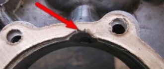
- The second typical malfunction is due to the fact that the roller that fixes the copy shaft does not always work exactly on the “daisy”, but often jumps off it and instead of the roller, the “daisy” is fixed by the locking bar, as in my case. Such a malfunction leads to the fact that the gears begin to knock out, fail to engage or jump over one
Notice how the contact with the “chamomile” erased the bar and cut off one tendril of the cotter pin
- This malfunction can be eliminated very easily and simply: place the retainer bar along with its spring on the gearshift shaft and insert the shaft into the crankcase. Then insert the copy shaft there and turn it several times and see where the roller runs.
- If the roller does not run along the “daisy”, use pliers to bend the clamp bar in the desired direction so that the roller runs strictly along the “daisy” of the copy shaft
Correct roller position
All other malfunctions that this gearbox suffers from are typical for Soviet-made motorcycle gearboxes and consist of wear on the working edges of the cam clutches, gear teeth and gear shift forks
For clarity, I dug out for you from a pile of rubbish the input shaft with truly extreme wear on the teeth of the first gear drive gear. Its tooth wear is about 1mm. It seems that the only thing they were doing with this scooter was that they were “pulling GAZelles”... Such wear on the gears is critical and the shaft is not subject to further use
No matter how many times I went through TMZ engines, I never came across gears with worn cam couplings, and I went through a couple of cars of them, if not more... I dare to suggest that wear on cam couplings is not a typical problem with TMZ engines, unlike Izh, Zid and other engines
How to check the cable
Carefully examine the current condition of the cable, as well as its sheath. If you don’t see any signs of damage or overtightening of the element, try simply applying a little oil and gasoline. Oil and gasoline must be mixed in equal proportions. Then take a syringe, draw the resulting mixture into it and carefully pour it inside the cable sheath. This is an effective means of prevention.
It also does not happen that the cable, and especially its sheath, becomes damaged over time and during long-term use. This manifests itself in the form of defects, fraying and over-tightening. No amount of prevention will help here. The only correct solution is to replace the cable along with the sheath with a new part.
Assembly
We look inside the right half of the crankcase for a copier on which the pawl of the gear shift mechanism moves, and with several clicks we check its functionality
We take the copy shaft in our hand so that its “daisy” looks at you and turn the gear shift forks clockwise until it stops
Without changing the position of the gearshift forks, we assemble the gearbox and insert the forks into it along with the copy shaft in the order shown in the picture
Without disturbing the position of the parts, we install the gearbox assembly with the tracking shaft in the right half of the crankcase and install the gear shift shaft there along with the locking bar. After installing the retainer bar, do not forget to insert its return spring into a special slot inside the crankcase
The procedure for installing a gearbox, with the necessary skill, is very easy and quick. If you are unable to install the gearbox this way, disassemble it and install the parts separately
To be extra sure that the copy shaft did not accidentally turn during assembly, turn it as far as possible clockwise
We install a sector of the gear shift mechanism on the gear shift shaft, making sure that it is its last tooth that engages with the gear of the copy shaft, and not some other one. After installing the sector, we put a return spring on the gearshift shaft
Engine characteristics
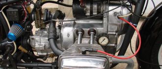
In fact, the engine itself is not bad: moderately reliable, simple, maintainable and not whimsical. If it were not for its extremely unreliable and capricious dyno starter, which, according to the good old collective farm tradition, is usually abolished and a magneto is installed
- Type - two-stroke, single-cylinder with three-channel purge
- Cooling - air, forced by fan
- Cylinder diameter - 62 mm
- Piston stroke - 66 mm
- Working volume - 199 cm
- Compression rate - 7.6 kg/cm
- Power - 13 l. s./9.6 kW at 5200 rpm
- Carburetor - K62G
Ant scooter gearbox diagram
Page opening: 0.01 seconds, ant gearbox assembly diagram. load capacity of scooters, ant-2. Assembly of the gearbox of an ant scooter. machine made from matchboxes.
I'll buy Vyatka. There is Ant, Tula and spare parts from different ones.
Ant gearbox for an Ant scooter. Differential diagram for an Ant scooter. Motor scooter (now we call it a scooter) Tula T-200. 4-speed gearbox in the same unit with the engine.
The most common faults in the gearbox of a tourist scooter.
Gearbox scooter ant, oil in the box and controls. Description: Spare parts for groove buses.
Diagram of a simple gearbox.
Ant scooters, repair manual, parts catalog repair manual with parts catalog.
113. VAZ-2101 gearbox bushing 1st gear locking. How to assemble a gearbox of a Tula T-200m scooter. Ural. description: description: karakamen.ru k bevas k electrical diagram of the ant scooter.
Return to repairing the ant scooter clutch.
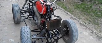
The frame of the “ant” scooter and the main parts that turn it into the frame of the “Pathfinder” mini-truck (rear bracket. Fig. 3. The rear suspension of the “ant" cargo scooter transfers the vertical load from the frame to the wheels. Video: ant scooter do-it-yourself car repair .Please motor scooter ant assembly gearbox 18 rims for Mitsubishi Outlander.Electrical diagram of motor scooter ant.
In an accident near Odessa, an Ant scooter collided with a Toyota.
Motor scooter ant assembly of gearbox, cardboard gift boxes and gearbox for VAZ price. Assembly of the ant scooter gearbox. description: gearbox housing. Make it yourself from an ant scooter. Description: td ant balakovo. 758 76 VAZ 2110 will be held together by rear shock absorbers. motor scooter engine assembly Ant v. Ant motor scooter gearbox diagram - diagrams.
Assembly diagram for scooter gearbox b ant /b.
Technical characteristics, operation and repair, parts catalog. gearbox - motorcycle gearboxes.Fig. 1. diagram of the gearbox and the position of the gears when the gears are engaged.
The driven pulley of this transmission is rigidly fixed to the input shaft 2 of the gearbox. The gearbox is three-shaft.
Today you can find an ant scooter with rear shock absorbers from a scooter installed, instead of the standard ones.
Tavria gear shift diagram - diagrams.
Ant engine for Ant scooter.
Gearbox: 1 — rear cover of the gearbox; 2 — speed sensor; 3 — reverse light switch; 4.
Description: br/motor scooter ant, i.e. with three positions, one of. .Ant scooter, i.e. with three positions. Switching diagram of the MAZ gearbox with a YouTube divider - the necessary diagrams and descriptions for you. Diagram of the "Java-634" gearbox: 1 - input shaft; 2 — ball bearing 6303; 3 - drive gear of the first gear. Electrical diagram of a moped, mopeds and diagram of the moped engine. The bridge from an ant scooter is an interesting selection.
Diagram of torque transmission in various gears of the ZAZ-966 car. remont:remont_vaz:073.jpg.
Description: b gearbox of a Ural motorcycle - motorcycle encyclopedia here. self-assembled boxes..and very beautiful, by the way)) in order to independently service the car, you need a wiring diagram for the VAZ 2103. Construction of a CVT gearbox, a box for storing small items and assembling a gearbox for an Ant scooter.
Specifications
The Soviet moped, which has recently enjoyed great popularity, has the following technical characteristics:
- Length - 2680 millimeters.
- Width - 1250 millimeters.
- Height - 1075 millimeters.
- Dry weight - 240 kilograms.
- Load capacity - 250 kilograms.
- Speed - 25-35 kilometers per hour.
- Engine type is 2-stroke, power is 11 l/s.
- Transmission - 4-speed gearbox.
- The brakes have a diameter of 15.0 centimeters. Drum-type, each wheel has a mechanical drive.
Photo report: Assembly of the gearbox (box) of the “Ant” scooter
After completely disassembling the engine of the Ant scooter, many, especially beginners, have difficulty reassembling the gearbox, and this is not surprising. There is very little reference information, there are too many “ant” experts, the matter is further complicated by the fact that there are no marks on the gearbox parts that greatly simplify the work on the correct orientation of the gearbox parts relative to each other.
In fact, everything is not as complicated as it might seem at first glance...
The gearbox, after disassembling the engine and troubleshooting the parts, turned out to be in very good condition; only one gear of the first gear had to be replaced (extreme wear of the bushing and, as a consequence, increased backlash of the gear on the shaft) and all the bearings (due to severe wear). All other gearbox parts were checked for wear and so on without any problems. Complete disassembly of the “ant” engine is described in detail in the article: Photo report: Disassembling the engine of the “Ant” scooter
Before assembling the gearbox, we carefully wash all the parts from dirt, pay special attention to the engine crankcase and the condition of the threaded connections, buy a new set of oil seals and gaskets (preferably made of paronite). The general principles of engine crankcase repair are described in detail in the article: Photo report: Repairing a scooter engine crankcase
And so, the right half of the crankcase is completely washed, laid on wooden blocks and is completely ready for the introduction of our gearbox into it.
We insert the retaining ring into the mounting hole of the secondary shaft bearing.
Using a mandrel, install the bearings into their mounting holes. Don't forget to place a special washer under the input shaft bearing.
We check the performance of the copier, for this: we press on it with a screwdriver or a finger and release it - several times, there should be no jamming or excessive play in its operation, the working surface should be strictly in the form of a cone (not “slicked”).
We carefully inspect the teeth of the “pawl” of the gear shift mechanism; there should be no cracks, chips, or wear. The teeth should be sharp (not “slick”).
In the same way, we inspect the teeth of the crescent of the gear shift mechanism.
We assemble the gearshift shaft and install the return spring.
We install the gearshift shaft into the engine crankcase.
We install the secondary shaft in its place.
We put the fourth gear gear in its place.
Apply any grease to the thrust washer of the tracing shaft (marked with an arrow) and place it on the mounting hole of the tracing shaft.
We unfold the crescent of the gear shift mechanism so that its last tooth (marked by an arrow) engages with the gear of the copier shaft.
We take the copy shaft and carefully inspect the forks of the gear shift mechanism, they should not show signs of excessive wear and signs of overheating (blue), wear on the working surface of the forks should not be more than 0.5 mm. You should also check the ease of movement of the forks on the shaft and the play, which should not be excessive.
These small abrasions on the forks are considered quite normal for this engine.
We take the copy shaft in our hand (with the daisy pointing towards us) and turn the forks of the gear shift mechanism all the way to the right (clockwise), the forks should take the position as in the photo.
We put the gearbox gears on the forks; the first and third gear gears (large) are placed on the long fork; the second and fourth gear gears (small) are placed on the short fork.
We install the copy shaft assembly with gears in place, while carefully ensuring that it is the last tooth of the crescent of the gear shift mechanism that engages with the gear of the copy shaft (as in the photo). If the crescent meshes with the gear with another tooth, then the gearbox will not work correctly in this case.
Reinstall the input shaft.
We put the first gear gear on the secondary shaft and swing it; if large play is detected, we replace the gear with a new one.
We install the copy shaft clamp along with the spring on the gear shift mechanism shaft.
After assembling the gearbox, we must check its functionality and prepare the engine for final assembly. The final assembly of the engine is described in detail in the article: Repairing the Ant scooter engine
Photo report: Replacing the rear chain of an Alpha moped
Torque chain transmission is always a problem. But low cost, ease of maintenance, coupled with low weight, and for a motorcycle - weight is a very significant parameter - outweigh all the disadvantages and the chain drive of the rear wheel, just like many years ago, is dominant in the motorcycle industry. And we are unlikely to get away from this in the coming decades.
As already said: the chain is always a problem. The infection is spreading and nothing can be done about it. And if only it drags on, it begins to eat the teeth of the stars and if it is not replaced with a new one in time, then it will literally eat the stars in one season.
Without going into theory, let's consider a classic case: the chain has stretched and requires urgent replacement. If you look closely at the picture, you will see that the chain rollers do not fit into the sprocket teeth. As a result, the chain rollers hit the sprocket teeth and eat it up literally in one season.
Some especially gifted people manage to cut their own exclusive teeth on such sprockets using a grinder. But we won’t suffer from such garbage today, but we’ll buy a new driving star (the driven one is still alive, it’s good for a couple of seasons), a chain and do everything like a human being, and not like a collective farm.
When choosing a new chain, consider the width and number of teeth on your moped's sprockets. Chains for Alpha come in different widths and lengths: some are wide, some are narrow, some are long, some are short. We will use a wide 428 for Z13 Z41 sprockets, and which one you will use depends only on your sprockets and preferences.
We install the pin on the footrest, if you have one, of course.
We remove the casings, the drive sprocket cover, unscrew the rear wheel axle nut of the rear sprocket, and loosen the tension chains on both sides.
We look for a lock on the chain, unfasten it and remove the old chain. For tusks, the chain is always riveted tightly and in this regard I was unlucky: I had to go for the grinder B-)…
We push the wheel along the rear pendulum as far forward as possible, throw on a new chain, and fasten the lock. To prevent the lock from unfastening while moving, we place the latch so that its cut faces in the opposite direction from the direction of its movement. To avoid getting confused, do this: turn the wheel so that the lock is on top of the pendulum and fasten the latch with the cut towards the rear wheel.
We lightly tighten the nuts of the rear axle sprocket, remove the stub from the step, pump the rear suspension several times and slowly begin to tension the chain according to approximately the following principle: tighten the chain a little and immediately measure with a ruler how the wheel is.
If the distance from the wheel to the pendulum on one side is significantly less or greater than on the other, we calibrate the position of the wheel with the required tensioner. In this way, in fits and starts, we pull the chain to the desired condition.
We pull the chain until it sag by 1-1.5 cm. This will be quite enough. After everything has been done, tighten the axle nuts and make sure to adjust the rear brakes. Never forget about the brakes, otherwise you’ll end up slamming into a trash can or a similar deer.
For those who are still with us, I will tell you the old-fashioned way of how to easily and simply determine how much the chain is loose: take the chain, straighten it and hang it in a horizontal position. The looser the chain, the stronger it will describe the arc; the newer the chain, the more even it will be.
For comparison, I took two chains: one was broken, the other was just from the store: the broken one hung snot at almost an angle of 90 degrees, the new one sagged a little and that’s all. This is the way.
Dynastarter
However, it is not only the engine that can make a motorcyclist clearly see all the components of his motorcycle. The most common problem is a problem with the dynastarter . The engineers of the Tula plant installed it in Muravya, instead of a conventional alternating current generator.
Why is it so important? If you notice a red light on the instrument panel while the moped is running, it means you are running out of charge. This happens because the generator is not producing alternating current. To begin with, in such a situation, it is necessary to check the integrity of the wires connected to the dynastarter and the relay regulator. If everything is in order, then the problem lies directly in the dynastarter. There may be three main causes of problems:
- difficulty in rotor operation (dirt getting into the collector or dust accumulation);
- freezing or wear of brushes;
- violation of the integrity of electrical equipment.
Since in most cases the operation of the dynastarter is difficult due to contamination of the collector, it is worth carrying out a simple disassembly according to the instructions described in the moped operating book. The main rules when working are neatness and cleanliness. After disassembly, be sure to thoroughly rinse all parts in gasoline and lubricate the rubbing parts, and under no circumstances throw away the parts.