GENERATOR 700 W | OPPOZIT.RU | motorcycles Ural, Dnepr, BMW
The resistance between the windings must be the same.
The engine is started and the rotor rotates in the stator winding, voltage is supplied to the excitation winding through the PP and the generator is excited. As practice has shown, pieces of nails driven into holes cope with the task. If the voltage is outside the technical specifications, replace the regulator. In particular, automatic ignition timing was introduced, since the motorcycle received a new power unit, and the old manual control of the timing advance did not meet the technical requirements. The voltmeter reading is noted and, by bending the shank in the voltage relay, the spring tension is increased, and with it the generator voltage by 0.4 V. An additional rectifier arm is also introduced into the electrical circuit. During this period, you can slightly increase the generator voltage.
On a URAL car there is a voltage regulator. If the voltage is outside the technical specifications, replace the regulator. Adjust the position of the front wedge stops 9 on the closed lid 6 of the container 10 after installing the batteries 1 and the upper clamps into the container. If they come out of the special sockets, the phase leads may break off during generator operation.
If the engine continues to run, then the generator is working. The work consists of connecting a generator or battery to the mains at a certain moment. Thus, by turning the additional resistance on and off, a certain generator voltage will be maintained. After installing the batteries on the car, adjust the position of the front wedge stops 9, for which loosen the tightening of the bolts 8 securing the stops 9 to the cover 6, move the stops 9 along the elongated holes of the cover 6 away from you until they stop and tighten the bolts 8.
We recommend reading:
Contact Information. Thus, by turning the additional resistance on and off, a certain generator voltage will be maintained. Remove the cover from the shaft.
But you need to follow some rules. The generator covers undergo minor modifications. Replace brushes protruding from the brush holder channel by less than 5 mm. Features of the development of electrical equipment of Ural motorcycles The six-volt circuit over the years ceased to meet technical regulations, and on subsequent models, manufacturers installed central wiring designed to operate 12V equipment: Ti-volt battery; Let's consider their structure and interaction.
Thus, by turning the additional resistance on and off, a certain generator voltage will be maintained. If the voltage is outside the technical specifications, replace the regulator. Period of years The wiring of the Ural motorcycle has also proven itself quite well - if at first the designers had concerns about loss of contact due to possible corrosion of the metal frame, then operation has shown the reliability of the single-wire electrical circuit. Scooters and mopeds Ural motorcycle wiring diagram Ural motorcycles have a unipolar battery terminal. If after several trips it turns out that the battery is not charging enough, you can further increase the voltage of the generator, but not higher than 15 V. Ural motorcycle wiring diagram
To mainCHECKING THE OPERATION OF THE GENERATOR AND VOLTAGE RELAY REGULATOR
A complete failure of the generator can be easily detected based on a number of obvious signs. However, damage leading to a decrease in the generator current is not clear and is usually detected with a delay, mainly due to a constantly weak battery charge. The inconveniences of operating a motorcycle with a weakly charged battery are familiar to drivers and are expressed not only in difficulty starting the engine with all the ensuing consequences, but also in decreased riding safety due to the possibility of failure of the electric horn and weak headlights. Before we begin to outline methods for checking the generator and relay-voltage regulator, you need to clearly understand their electrical circuits and interconnections. Electrical circuit of a DC generator.
In fig. Figure 27 shows the electrical circuit of a simple shunt generator. An anchor is depicted in the center. To the right and left of it are two brushes. On top of the armature there is a pole piece with an excitation winding. One end of the field winding is connected to the right brush, the other end to the left brush. Generators with such a parallel connection of the field winding and armature are called shunt generators.
The external circuit (consumers) is also connected at two ends to the right and left brushes. Generators are manufactured not only with one pole piece (generator G-11 of the M-72 motorcycle), but also with two and four (generators G-35 and G-36 of motorcycles M1A, K-125, IZH-350 and IZH-49). In generators with several pole pieces, their windings are connected to each other in series, so that for connection to the brushes, as with one pole piece, there are also only two ends. A generator with a shunt excitation winding connected directly to the brushes excites well, but without a slight complication of the circuit it is not sufficiently suitable for operation on a motorcycle, since the voltage and current at the terminals increase as the number of armature revolutions increases. The crankshaft speed of a motorcycle engine varies over an extremely wide range - from approximately 500 to 5000 rpm. As a result, the generator, which develops normal voltage at moderate speeds, will overheat at full speed of the engine crankshaft due to an increase in voltage and current, the insulation of its windings will be charred, and the plates of the battery will be destroyed from too intense charging. If, on the contrary, we use a generator in the windings of which normal voltage develops at high engine speeds, then at average speeds the voltage and current will be insufficient. In order for the generator to be suitable for operation on a motorcycle engine, it is necessary to promptly include additional resistance in the field winding circuit as the speed increases, as a result of which the generator voltage fluctuation is leveled out, remaining within 6.5 - 8.5 V
. Despite the apparent complexity of the electrical circuits for including additional resistances in the excitation winding circuit and their abundance, they can essentially be reduced to two very simple circuits. According to the first electrical diagram (Fig. 28, a), additional resistance is connected between the end of the excitation winding and ground (generator G-11 of the M-72 motorcycle, generators with an L-shaped relay-voltage regulator installed on BMW and LVO-425 motorcycles).
According to the second electrical circuit (Fig. 28, b), additional resistance is included between the end of the excitation winding and the insulated brush (generators G-35, G-36 of motorcycles M1 A, K-125, IZH-350 and IZH-49, as well as a generator with double-anchor relay-regulator). The additional resistance for the excitation winding of generators G-11, G-35 and G-36 and two contacts that short-circuit the resistance are located outside the generator housing, in the voltage relay regulator. Consequently, until these generators are connected to their voltage regulator relays, there is an open in the shunt circuit and the generators cannot operate either as generators or as electric motors. To test the generator, the break in the shunt circuit must be repaired by installing a temporary jumper. The additional resistance in the generator installed on the BMW-R-35 and AVO-425 motorcycles is located on the pole piece along with the excitation winding. Electrical diagram of a reverse current relay.
The reverse current relay (Fig. 29) serves to disconnect the generator from the external circuit when the voltage it develops is lower than the battery voltage. To be included in the electrical circuit, the relay has three outputs: the so-called input terminal, connected to the generator terminal I; the output terminal from which the wire goes to the external circuit to the battery; the third terminal is the metal body of the device itself or a special wire connected to ground.
Two windings are wound on the core of the electromagnet of the reverse current relay. The thin winding is connected parallel to the armature brushes constantly. One end of the winding is soldered to the core of the electromagnet, which is connected through a thick winding to the input terminal. The other end is soldered to the metal body of the device or to a wire connected to ground. A thick winding at one end is connected to the input terminal, powered from terminal I of the generator, and the other end is soldered to the core of the electromagnet, connected to the armature on which the moving contact is located. When the armature is attracted to the electromagnet, magnetized under the influence of the increased voltage of the generator, the movable contact will be pressed against the fixed one connected to the output terminal, and the current will flow into the external circuit to the battery. Electrical circuit of the voltage regulator relay.
The voltage regulator maintains the generator voltage at a given level, automatically including additional resistance in the excitation winding circuit.
Voltage regulators installed on domestic motorcycles are combined with a reverse current relay in a common housing and have a common connection, forming a device called a voltage regulator relay. The reverse current relay has open contacts and closes
when the armature is attracted to the electromagnet.
The voltage regulator has contacts that are closed and open
when the armature is attracted to the electromagnet. Based on this external feature, it is easy to distinguish the reverse current relay from the voltage regulator and the contacts related to them in the device. Since the voltage regulator is included in the electrical circuit of the generator, it is more convenient to consider its structure and operation together with the latter. In fig. Figure 30 shows a diagram of the RR-1 voltage regulator relay and the M-72 motorcycle generator.
The device is connected to the electrical wiring by four terminals: terminal I with terminal I of the generator; terminal Ш with terminal Ш of the generator; terminal B with the negative terminal of the battery (or with the positive terminal, if in the electrical circuit the negative terminal of the battery is connected to ground); The fourth terminal is the metal body of the device, connected to ground with a fastening bolt using a spring plate. The voltage regulator electromagnet is constructed in much the same way as the relay electromagnet, and has a thin winding, constantly supplied by the generator, and a thick winding. In the generator under consideration, one end of the excitation winding is connected to an insulated negative brush at terminal I, the second end of the excitation winding is connected to terminal W, isolated from ground. The positive brush is connected to ground. Therefore, in order for the generator to operate, terminal Ш must also be connected to ground. The connection between terminal Ш and ground (Fig. 30, a) occurs in the voltage regulator (Fig. 31) along the following path: terminal Ш of the generator, wire, terminal Ш of the voltage regulator relay, core, armature, lower contact, upper contact, contact plate , stranded wire soldered to the stand, metal case, spring plate M, mounting bolt, ground.
At a high number of revolutions of the engine crankshaft, to reduce the generator voltage, terminal Ш should be disconnected from ground and additional resistance should be temporarily connected between them. A resistance (carbon plate) P is placed under the body of the device. One end of the resistance is connected to ground, the other to terminal Ш. The resistance is turned on and off by a voltage regulator. When the voltage regulator core is magnetized under the influence of the increased voltage of the generator and attracts the armature, the contacts will open, and the generator shunt circuit will not be directly connected to ground, but will be connected to it through additional resistance. In fig. Figure 30 shows three cases of joint operation of the generator and the relay-voltage regulator RR-1. Please note that when the engine is running, the relay contacts must close first and only then can the voltage regulator contacts open
. The voltage regulator relay PP-30 of the M1A motorcycle (Fig. 32), as well as the voltage regulator relay of the M-72 motorcycle, is included in the electrical wiring with four terminals. Its terminals I and Ш are connected to the corresponding terminals of the generator, terminal B is connected to the battery, and the housing is connected to ground. But the voltage regulator relay (PP-30) of the M1A motorcycle and the voltage regulator relays (PP-1 and PP-31) of the M-72 motorcycle cannot be replaced with one another without a radical change in the electrical circuit of the internal wiring of the generator.
In the M1A motorcycle generator, one end of the excitation winding is connected to ground (Fig. 33), and its other end is connected to terminal Ш.
The negative brush is connected to ground, the positive brush is connected to terminal I, isolated from ground. This means that the excitation winding is not connected to the positive brush. The necessary connection of the excitation winding with the brush, i.e., with the I terminal, occurs in the contacts of the voltage regulator. The closed contacts directly connect the excitation winding to the brush, and when they open, they turn on additional resistance. The voltage relay regulators of the IZH-350, IZH-49 and K-125 motorcycles (Fig. 34) are interchangeable with the voltage regulator relay of the M1A motorcycle, since the electrical circuits of the generators of these three motorcycles are the same. When replacing a voltage relay-regulator, the electrical wiring is assembled according to the diagram of the motorcycle to which the installed voltage relay-regulator belongs, which is associated with a change in the location of the devices, the length and location of the electrical wiring wire sections.
The voltage regulator relay for motorcycles IZH-350, IZH-49 and K-125 is located in the distribution box (Fig. 35).
The terminals of the junction box ДШ, Д+ А and AM, respectively, must be connected to the terminals ДШ (Ш), Д+ (И) of the generator, to the positive terminal of the battery and to ground, and therefore they are equivalent to terminals Ш, Я, B and ground motorcycle voltage regulator relay M1A. The L-shaped relay-voltage regulator of the BMW-R-35 motorcycle generator is located under the generator cover, forming a single unit with it. The AVO-425 motorcycle has an L-shaped voltage regulator relay located under the front engine cover, under the generator. The generator has two terminals labeled 51
and
61
These terminals correspond to terminals B and Z of domestic devices.
Methods for checking the generator and voltage regulator relay.
The warning light coming on at medium engine speeds is the first sign of a malfunction in the generator and voltage regulator relay.
When the generator is faulty, adjusting the voltage regulator relay is completely useless, so the generator must be checked first. This eliminates the waste of checking electrical wiring and adjusting the voltage regulator relay. The generator is checked in such a way that the influence of the voltage regulator is excluded on its operation. To check the M-72 motorcycle generator (Fig. 36), terminal W is connected directly to ground using a fusible jumper made of one or two thin wires of stranded wire, and both wires from terminal I are temporarily disconnected. For motorcycles M1A, K-125, IZH-350 and IZH-49 (Fig. 37), for the same purpose, a fusible jumper is installed between terminals I and Ш, and the wires going from these terminals to the wiring are disconnected during the test. Terminals I and Ш are equivalent to terminals D+ and DSh. W
, is connected to terminal I and to the ground of all disassembled generators . If the lamp does not light up either at an average speed or at a high number of revolutions, then the generator is faulty and its malfunction is not related to the state of the voltage regulator and reverse current relay.
In this case, it is necessary to thoroughly check the generator. If the light comes on at full intensity, but after connecting the generator to normal wiring, the control light still does not go out and the engine does not work without a battery, then this means that the voltage regulator relay or the wires connecting it to the generator are faulty. In this case, the voltage regulator relay first checks the condition of both pairs of contacts: the voltage regulator and the reverse current relay, and if the contacts are burnt, they are cleaned. Having carried out this work, connect the generator and relay-voltage regulator with electrical wiring, start the engine and disconnect the battery. If in this case the engine does not switch to operation from the generator, then, consequently, either the tension in the armature spring of the voltage regulator has weakened, or the armature spring of the reverse current relay is over-tensioned, or there is damage in its windings. Running an engine without a battery on one generator does not indicate that the generator is fully operational. The fact is that no more than 3 A
. Therefore, it is still necessary to make sure whether the current supplied by the generator to the external circuit is sufficient. To find out this, you can turn on a large light lamp. A generator capable of ensuring uninterrupted ignition and filament of a powerful lamp at medium and high engine speeds is quite serviceable. It is recommended, without taking into account the presence of a voltage regulator (and even more so when it is turned off), to increase the speed of the engine crankshaft gradually and at the same time continuously monitor the glow of the lamps in order to have time to reduce the number of revolutions in time and prevent the filaments from burning out . If, when the battery is disconnected, interruptions in the ignition appear when the lamps are turned on, or if the engine stops, it means that the generator current is insufficient and inspection, cleaning, repair and adjustment of the generator and voltage relay regulator are required. Before removing the generator from the engine of the M-72 motorcycle, open access to the brushes and, while turning the engine crankshaft, observe the commutator, since it is possible that the armature does not rotate due to its gear disengaging with the timing gear. A possible cause of malfunction of this generator, in addition to contamination with oil and coal dust, is a short circuit of the winding to the housing (Fig. 38) or intraturn (irremovable) short circuits of the armature winding, accompanied by darkening of individual plates or groups of collector plates. Generators of motorcycles M1A, K-125, IZH-350 and IZH-49 have a typical malfunction - a violation of contact between the brush and its conductor, followed by overheating and burning of the brush, conductor and spring. Before disassembling the generator, check the condition of the brushes.
To preliminarily check the generator of a BMW-R-35 motorcycle, the control light of which has stopped going out, first of all, find out whether the armature rotates normally while the engine is running. To do this, check whether the drive belt has broken and whether its tension has weakened. Due to insufficient tension, the belt slips along the pulleys and rotates the armature at an insufficient number of revolutions. If the belt tension is normal, then use a test light to check the presence of current at the terminals 51
and
61
generators.
to terminal 51
and ground only to determine whether the power supply to consumers from the generator has stopped as a result of damage to the electrical wiring.
If the light from terminal 51
does not light up, but lights up when connected to terminal
61
, this indicates that the generator is working, but the reverse current relay is faulty.
In both cases, it is necessary to thoroughly check the generator and the voltage regulator relay located under its cover. Previous page
| table of contents | Next page |
How to check the relay?
In general it was like this. I was getting ready to start my trike, which had been sitting outside all winter. After charging the battery, cleaning the contacts and replacing some substance in the gas tank with gasoline, I finally revived it. And since the ignition key was lost and the lock itself was completely broken, I could not turn off the ignition. This means the engine is working, but I don’t have the brains to take off the candle holder to turn it off (there is no engine stop). So, instead of disconnecting the positive wire going to the coil, I short it to ground. The engine died down and, in general, all signs of life along with it. I looked at the fuses, one was burned out, I replaced it, everything was still dead. To clarify, this means that the charging control lamp does not light up. Then I took a piece of wire and connected the plus directly to the coil. The lamp does not light, mind you. So I start it and the light comes on. I have a separate breaker for the generator, so I turn on the generator, the lamp starts blinking. I turn off the engine, the lamp goes out. So the main question! Which of the two relays burned out? The wiring works according to the scheme described in https://custom26.ucoz.ru/forum/5-127-1
nait9, the control light is in your hands. and check for the presence of a plus where it should be. With a multimeter in low-resistance circuits, there is little that can be adequately checked other than the integrity of the wires.
IMHO the relay-regulator burned out. When my control lamp relay burned out after a short circuit, the control lamp was constantly shining, despite the fact that the RR was regularly charging. If you buy a new RR, look for one with diagnostic LEDs. RRs are the size of a matchbox.
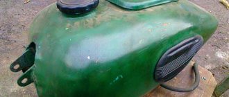
All is good! The topic can be closed. I decided to do as Vetal41rus advised. I checked the power supply to the lock using a test lamp. Not finding it there, I took a piece of wire and connected it directly from the plus of the generator to the lock. The lamp works, the engine starts, the gene snorts. Looks like the wire has burnt out. Remove the tank. I just filmed it again. Eh.
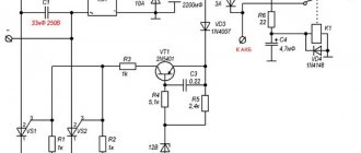
How to make a relay regulator with your own hands?
To make a relay regulator with your own hands, you need a diagram and a little knowledge. The model of a homemade regulator is based on the principle of disassembling the generator and outputting a separate end of the wire from ground.
As a diagram, you can take the relay-regulator connection diagram (Figure 3), and on its basis assemble a single-phase generator.
To collect the stabilizer you need:
- disassemble the generator and remove the stator from the engine;
- then you need to unsolder the ground from the generator, solder a separate additional wire for the winding to it and bring it out. This wire will be one end of the winding. The second end is the generator wire;
- After removing the wires, you need to reassemble the generator in reverse order.
With this device, the generator has 2 wires (there should be 3 in total). You can connect the stabilizer according to this scheme:
Do-it-yourself relay-regulator manufacturing diagram
At the end of the process, you need to connect the yellow wire from the old regulator to the “+” terminal in order to obtain a constant voltage on the sides of the network. Check the resulting voltage regulator on the scooter. At this point, the process of creating a homemade device can be considered complete.
The relay regulator is a very useful thing and necessary for the normal operation of the moped. However, it requires attention and constant monitoring of its work. Therefore, if the device fails or its performance is unsatisfactory, it is better to replace it with a new one, the cost of which today ranges from 300 to 500 rubles.
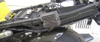
Installing the fan on the motorcycle regulator relay
In a computer hardware and organizational store. technicians, we purchase a fan for the ATX power supply.
Better than Zalman and even better than aluminum or ceramic, I couldn’t find aluminum, although they are on sale, the fan size is standard 80x80mm.
If you have a motorcycle model other than the Honda VFR 800 or Honda VFR 400, then you first need to assess the space to see if the fan will fit, usually there is enough space; on the motorcycle models listed above there is more than enough space.
On Honda VFR motorcycles, the relay regulator has a radiator for better cooling, as practice shows, this radiator is not enough.
The fan cannot be glued to the radiator of the regulator relay, the latter gets very hot and no glue, with the exception of thermal glue, will withstand such a temperature. Due to the vibration, it will most likely just come off sooner or later.
How to attach a fan to a motorcycle relay regulator.
The easiest way is to make wooden spacers - a wooden dowel, also known as a “bonnet”, the width of the spacers should be exactly the same as the grinding area in order to fit between the radiator fins on the regulator relay. The size is determined experimentally, with a little pressure; do not overdo it; it is better to sharpen it.
We push spacers between the radiator fins, taking into account the width and height of the fan. If you mount the fan through the lower holes, then use 10mm screws or 25mm screws if you mount it through both eyelets of the fan, then tighten the fan to the radiator.
The wires going to the fan will have to be built up with similar ones.
The red wire on the fan is positive, the black wire is negative.
It is better to connect the fan to the side lights of the motorcycle, because... We all always drive with the lights on, and our lights are always on as well.
Look at the photo and questions about the mechanical installation of cooling will disappear by themselves; if they arise, it’s just not always clear from the description.
Electrically, there is also nothing complicated, you just need to determine the negative wire and the positive wire on the side lights, you can resort to reading the instructions (manual) for the motorcycle, or use the outside help of a more knowledgeable motorcycle partner, or simply use a voltmeter.
If you are not familiar with a multimeter, then in a nutshell you can find out where the plus and where the minus of the two wires is.
We set the multimeter to the “Volts (V)” measurement mode; next to it, there is not a sine wave drawn, but a straight line.
We touch the wires with probes, if the screen shows, for example, the value “–11.86V”, it means that where the black wire is, there is a positive wire on the motorcycle. If the value on the screen is without the “-” sign, then the positive wire will be under the red probe.
What other relay regulators can the fan be installed on?
I would also like to add that for those relay regulators that heat up and do not have their own radiator, the installed “cooler” from the computer processor, both with and without a radiator, helps a lot, it is possible to bring it down to 10-25 degrees, which in itself In some cases, the relay regulator saves itself.
However, installing a fan of even a smaller diameter in a narrow place is sometimes extremely difficult, then use a fan for video cards, again computer ones, such fans can be glued using thermal glue, in no case should you use ordinary glue, any strings, clothespins, etc. you need to make sure that it lasts forever and in no case falls off anywhere at high speeds.
It is highly advisable to add comments to the article, if there are any, of course.
How to check PP with a multimeter on a moped?
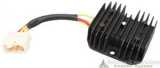
The relay regulator on a Chinese scooter is checked using a multimeter with a voltmeter function. For this purpose, a simple DT-830 (or equivalent) is usually used. It is better to carry out diagnostics and measurement of output voltage with the device removed.
Verification algorithm:
- You need to unscrew the fairing with the central phase and find on the frame a device with 4 wires: red, green, yellow and white.
- Then start the scooter and check the voltage at idle: measure it between the green and red wires, setting the multimeter to the maximum value of 20 V.
- If the multimeter display shows a figure of 14.6-14.8 V, this is normal. For stabilizers on Chinese mopeds, this is the operating standard voltage. If at idle the multimeter shows a value of 15-16 V, this is a high voltage indicator. This indicates a malfunction of the relay regulator.
- Then you need to check the voltage supplied to the lighting lamps. An alternating voltage is supplied to the central low beam (high beam) lamp, so the multimeter should be switched to the alternating current measurement mode with a parameter of 20 V.
- Next, we measure the voltage between the green and yellow wires (green is the general electrical network of the moped). If the multimeter shows a network voltage of up to 12 V, then the electrical appliances are operating without additional load.
- If at idle this value is 16 V or higher, and with a sharp increase in engine speed it jumps to 25 V, the device does not stabilize the voltage and, therefore, does not work. With such readings, the device must be replaced with a new one.
Using a multimeter, they check the relay regulator on a Chinese scooter.
In order to make a measurement, you need to:
- switch the device to the “KiloOhm” mode and remove the regulator;
- then place the probes on the first pair of terminals (AB). The tester should show a value of no more than 18 kOhm;
- after that, we change the position of the probes on the terminals in the opposite direction (VA) and measure the voltage again - the arrow on the device should show 0;
- then we install the probes on the next pair of terminals (SD) and measure the readings on this pair;
- swap the probes (DS) and measure the indicator again;
- the remaining measurements have no contact and are not checked. The indicator when checking them should be zero.
In this way, regulators are tested on popular Japanese models with small engine volumes from brands such as Honda (Leard, Dio, Tact), Suzuki, Yamaha.
Replacing a faulty relay regulator on a scooter is not difficult.
Transistor series voltage regulator
This regulator has a transistor connected in series with the Zener regulator and both in parallel with the load. The transistor acts as a variable resistor that regulates the emitter voltage at the collector to maintain a constant output voltage. The figure below shows a transistor series voltage regulator.
Under input operating conditions, the current through the base of the transistor changes. This affects the voltage at the base emitter junction of the VBE transistor. The output voltage is maintained by the constant voltage of the zener diode VZ. Since both are held equal, any change in input power is indicated by a change in the base emitter voltage VBE.
Therefore, the output voltage Vo can be understood as
VO=VZ+VBE
Operation of transistor voltage stabilizer series
The operation of the series voltage regulator should be taken into account when the input voltage and load change. If the input voltage increases, the output voltage also increases. But this, in turn, leads to a decrease in the voltage at the base junction of the collector VBE, since the Zener voltage VZ remains constant. Conductivity decreases as resistance increases in the collector region of the emitter. This further increases the voltage at the collector emitter junction VCE, thereby reducing the output voltage VO. This will be similar to decreasing the input voltage.
When load changes occur, which means that if the load resistance decreases, increasing the load current IL, the output voltage VO decreases, increasing the base emitter voltage VBE.
As the emitter base voltage VBE increases, conductivity increases, decreasing the emitter collector resistance. This in turn increases the input current, which compensates for the decrease in load resistance. This will be similar to increasing the load current.
Limitations of Transistor Voltage Stabilizer Series
Transistor series voltage regulators have the following limitations −
- Voltages VBE and VZ are affected by increasing temperature.
- Good regulation for high currents is impossible.
- Power dissipation is high.
- Power dissipation is high.
- Less effective.
To minimize these limitations, a transistor shunt regulator is used.
Signs that a check is needed
If the battery on your scooter often runs out, and it is still quite new, this means that there is a problem with the operation of the relay regulator. As practice shows, it burns out quite often. If the device is faulty, the battery stops charging completely and loses its capacity. This means you won’t be able to start the scooter with a button; you’ll have to start it with a kickstarter.
Another characteristic sign of incorrect operation of the device may be the frequent burnout of incandescent light bulbs. They themselves are durable and have a good durability, but are quite sensitive to voltage changes. This happens because the optimal voltage in the scooter network is considered to be 12-13 V. Increasing this value even by 2 V reduces the service life of electronics and components by 2 times.
Signs of a malfunctioning regulator are identical for all models of Chinese scooters. They are especially typical for charging relays for scooters of Chinese models with an engine capacity of 50 cc. Therefore, before making a decision to replace something in electronics, testing systems and devices should begin with the relay regulator.
For all models of Chinese scooters, the symptoms of a malfunction of the regulator are identical.
What is Voltage Regulation?
A voltage regulator is an electronic or electrical device that can maintain the voltage of a power source within suitable limits.
Electrical equipment connected to a voltage source must be able to withstand the magnitude of this voltage. The source voltage must be within a certain range acceptable to the connected equipment. This goal is achieved by implementing a voltage regulator. A voltage regulator - as it implies the same thing - regulates the voltage, regardless of the input voltage adjustments or the connected load. It acts as a shield to protect devices from damage. It can regulate both AC and DC voltage, depending on its design. After you study our article, you can buy a 10 kW stabilizer.
Checking the ignition coil
Disconnect the battery and remove the beak on the scooter. We disconnect the connector on the switch and measure the resistance on the coil with a meter. We put one probe in the connector on the black wire, and the second on the negative (green wire). There should be 4 ohms - this means that the wiring and the primary winding of the coil are working properly.
Next step.
We check the second winding of the coil. We take out the probe from the contact of the green wire and insert it into the candlestick instead of the candle. And we leave the other probe on the contact of the h/w wire. The resistance should be about 7.85 kOhm. This indicates that the second winding, the armored wire and the candlestick itself are in good working order.
And if the device shows a break (i.e. does not react at all), then remove and check the candlestick and armored wire separately. If they ring, it means a break has occurred in the ignition coil. It cannot be repaired, it is solid, you will have to replace it with a new one. It's inexpensive and you can always buy it without any problems.
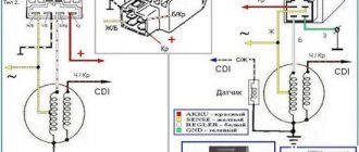
Scheme and principle of operation
The operation of the stabilizer for all models is almost the same and consists in distributing the current supplied from the generator to stabilize it and further distribute it to consumers.
The operation of the stabilizer is almost the same for all models
The main peripheral consumers of the scooter include:
- battery;
- indicators;
- light bulbs;
- sensors;
- enrichment agent;
- other nodes;
- starting enrichment.
How does the stabilizer work? The main principle of its operation is to act as a transformer, which lowers the voltage to an optimal level acceptable for the operation of electrical appliances, and also stabilizes the network and prevents unexpected power surges.
To avoid these problems and their undesirable consequences, you should know the basics of the correct operation of the electrical circuit and voltage components of the scooter (Figure 1).
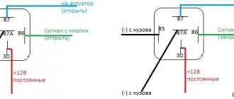
Voltage relay pinout diagram and wiring for main scooter models
The pinout of the relay regulator is standard for all models of Chinese-made scooters.
Scooter relay-regulator pinout
The stabilizer has an aluminum body and plastic contacts, each of which has its own wire. Each contact has its own wire color. This makes it convenient to connect the device to the wires if the plastic connector is worn out. The wires must be connected to the contacts according to the electrical diagram (Figure 3).
Electrical diagram for connecting the relay regulator
Transistor Shunt Voltage Regulator
The transistor circuit of the shunt regulator is formed by connecting a resistor in series to the input and a transistor, the base and collector of which are connected by a zener diode, which regulates both in parallel with the load. The figure below shows the circuit diagram of a transistor shunt regulator.
Operation of a transistor shunt voltage stabilizer
If the input voltage increases, VBE and VO also increase. But this happens initially. In fact, when Vin increases, the current Iin also increases. This current, when flowing through RS, causes a voltage drop VS across the series resistor, which also increases with Vin. But this causes Vo to decrease. This decrease in Vo now compensates for the initial increase, keeping it constant. Therefore, Vo is kept constant. If the output voltage is reduced instead, the opposite occurs.
If the load resistance decreases, there should be a decrease in the output voltage Vo. The current through the load increases. This leads to a decrease in the base current and collector current of the transistor. The voltage across the series resistor becomes low as current flows rapidly. The input current will be constant.
An output voltage will appear, which will be the difference between the applied voltage Vi and the series voltage drop Vs. Consequently, the output voltage will be increased to compensate for the initial drop and hence will be kept constant. The opposite occurs if the load resistance increases.