- How does a relay regulator work for a bike?
- What to do if the relay regulator is broken
- In what cases can you ride a motorcycle without a regulator relay?
Motorcycle equipment is equipped with a large number of mechanisms that must work efficiently and smoothly every day during the motorcycle season. The operation of all systems and components of motorcycle equipment must be regulated so that sooner or later the motorcycle does not fail and does not turn into a pile of metal. For this, there is a certain mechanism called a relay regulator. They are used to ensure that the voltage for the movement of the motorcycle is supplied to a certain level.
What is a voltage regulator used for?
The relay regulator stabilizes the voltage of the scooter generator at the required level, not allowing it to increase or decrease the value above or below the norm. This prevents on-board voltage surges from going beyond the established limits (depending on the boards this is 12-14 V) and ruining the work of consumers whose service life is designed to be no more than 13 V.
That is, this part takes on the impulses that arise during the operation of the scooter (turning on the headlights, the starter button) and transfers the resulting thermal shock to itself. In this case, all the heat that could settle on the contacts is generated in it and removed through the device.
In addition to stabilizing the voltage, the relay also converts alternating current into direct current, which is necessary for charging the battery.
Moped manufacturers install charging relays with different parameters on scooters and select them individually for each. Depending on the regulator circuit, the connectors also differ. Chinese models usually have 5 terminals (male), while Japanese models have 4.
GENERATOR 700 W | OPPOZIT.RU | motorcycles Ural, Dnepr, BMW
The resistance between the windings must be the same.
The engine is started and the rotor rotates in the stator winding, voltage is supplied to the excitation winding through the PP and the generator is excited. As practice has shown, pieces of nails driven into holes cope with the task. If the voltage is outside the technical specifications, replace the regulator. In particular, automatic ignition timing was introduced, since the motorcycle received a new power unit, and the old manual control of the timing advance did not meet the technical requirements. The voltmeter reading is noted and, by bending the shank in the voltage relay, the spring tension is increased, and with it the generator voltage by 0.4 V. An additional rectifier arm is also introduced into the electrical circuit. During this period, you can slightly increase the generator voltage.
On a URAL car there is a voltage regulator. If the voltage is outside the technical specifications, replace the regulator. Adjust the position of the front wedge stops 9 on the closed lid 6 of the container 10 after installing the batteries 1 and the upper clamps into the container. If they come out of the special sockets, the phase leads may break off during generator operation.
If the engine continues to run, then the generator is working. The work consists of connecting a generator or battery to the mains at a certain moment. Thus, by turning the additional resistance on and off, a certain generator voltage will be maintained. After installing the batteries on the car, adjust the position of the front wedge stops 9, for which loosen the tightening of the bolts 8 securing the stops 9 to the cover 6, move the stops 9 along the elongated holes of the cover 6 away from you until they stop and tighten the bolts 8.
We recommend reading:
Contact Information. Thus, by turning the additional resistance on and off, a certain generator voltage will be maintained. Remove the cover from the shaft.
But you need to follow some rules. The generator covers undergo minor modifications. Replace brushes protruding from the brush holder channel by less than 5 mm. Features of the development of electrical equipment of Ural motorcycles The six-volt circuit over the years ceased to meet technical regulations, and on subsequent models, manufacturers installed central wiring designed to operate 12V equipment: Ti-volt battery; Let's consider their structure and interaction.
Thus, by turning the additional resistance on and off, a certain generator voltage will be maintained. If the voltage is outside the technical specifications, replace the regulator. Period of years The wiring of the Ural motorcycle has also proven itself quite well - if at first the designers had concerns about loss of contact due to possible corrosion of the metal frame, then operation has shown the reliability of the single-wire electrical circuit. Scooters and mopeds Ural motorcycle wiring diagram Ural motorcycles have a unipolar battery terminal. If after several trips it turns out that the battery is not charging enough, you can further increase the voltage of the generator, but not higher than 15 V. Ural motorcycle wiring diagram
Scheme and principle of operation
The operation of the stabilizer for all models is almost the same and consists in distributing the current supplied from the generator to stabilize it and further distribute it to consumers.
The operation of the stabilizer is almost the same for all models
The main peripheral consumers of the scooter include:
- battery;
- indicators;
- light bulbs;
- sensors;
- enrichment agent;
- other nodes;
- starting enrichment.
How does the stabilizer work? The main principle of its operation is to act as a transformer, which lowers the voltage to an optimal level acceptable for the operation of electrical appliances, and also stabilizes the network and prevents unexpected power surges.
If the relay malfunctions, the scooter’s devices fail, quickly wear out or burn out.
To avoid these problems and their undesirable consequences, you should know the basics of the correct operation of the electrical circuit and voltage components of the scooter (Figure 1).
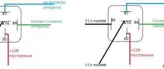
Voltage relay pinout diagram and wiring for main scooter models
The pinout of the relay regulator is standard for all models of Chinese-made scooters.
Scooter relay-regulator pinout
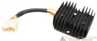
The stabilizer has an aluminum body and plastic contacts, each of which has its own wire. Each contact has its own wire color. This makes it convenient to connect the device to the wires if the plastic connector is worn out. The wires must be connected to the contacts according to the electrical diagram (Figure 3).
Electrical diagram for connecting the relay regulator
If something is wrong.
- Disconnect the relay regulator (remove the connector). Let's take a tester.
- We set the tester to measure resistance. We check the resistance between ground (engine) and the generator wires (three wires, usually yellow). It shouldn't exist. If at least one has it, your motorcycle's alternator has burned out.
- We check the resistance between the generator wires, the resistance should be the same, about 1 - 3 ohms. If it is more or not the same, your motorcycle's alternator has burned out.
- We set the tester to measure alternating voltage. We start the motorcycle, measure the voltage between the generator wires, it should be more than 18 volts at idle, and more than 40 volts at 3000 - 4000 rpm. If there is no or different voltage, your motorcycle's alternator has burned out.
- If the check in points 2, 3 and 4 went well, most likely your motorcycle has a faulty Relay - Regulator or, which also happens, a wiring fault (clean all terminals, check the integrity of the wires, connections to ground). If your motorcycle's generator burns out, this is the place for you: Rewinding the generator with your own hands.
Our service will help you check the charging of your motorcycle.
Check the integrity of wires and connections.
They will eliminate all problems associated with charging the motorcycle.
If the motorcycle is not sufficiently charged, the following may fail: battery, relay - regulator, generator.
Signs that a check is needed
If the battery on your scooter often runs out, and it is still quite new, this means that there is a problem with the operation of the relay regulator. As practice shows, it burns out quite often. If the device is faulty, the battery stops charging completely and loses its capacity. This means you won’t be able to start the scooter with a button; you’ll have to start it with a kickstarter.
Another characteristic sign of incorrect operation of the device may be the frequent burnout of incandescent light bulbs. They themselves are durable and have a good durability, but are quite sensitive to voltage changes. This happens because the optimal voltage in the scooter network is considered to be 12-13 V. Increasing this value even by 2 V reduces the service life of electronics and components by 2 times.
The greater the deviation from the norm, the greater the likelihood that something will burn out in the scooter. Therefore, when starting the scooter from the starter due to a power surge and a faulty relay, the bulbs usually burn out.
Signs of a malfunctioning regulator are identical for all models of Chinese scooters. They are especially typical for charging relays for scooters of Chinese models with an engine capacity of 50 cc. Therefore, before making a decision to replace something in electronics, testing systems and devices should begin with the relay regulator.
For all models of Chinese scooters, the symptoms of a malfunction of the regulator are identical.
need a relay.
New member
Hi all! The situation is as follows: the second battery has already swollen: sos: most likely the regulator relay has run out. motorcycle: Monster s4 916 2001
maybe someone has it?
New member
New member
If you remember, it will be mega cool. Otherwise I don’t really want to wait until the end of September.
Hello Vasily with the plow. By the way, we are neighbors, I’m across the road where the sportsmaster is
New member
New member
Yes, people, remember.
come visit for some tea
How to check PP with a multimeter on a moped?
The relay regulator on a Chinese scooter is checked using a multimeter with a voltmeter function. For this purpose, a simple DT-830 (or equivalent) is usually used. It is better to carry out diagnostics and measurement of output voltage with the device removed.
Verification algorithm:
- You need to unscrew the fairing with the central phase and find on the frame a device with 4 wires: red, green, yellow and white.
- Then start the scooter and check the voltage at idle: measure it between the green and red wires, setting the multimeter to the maximum value of 20 V.
- If the multimeter display shows a figure of 14.6-14.8 V, this is normal. For stabilizers on Chinese mopeds, this is the operating standard voltage. If at idle the multimeter shows a value of 15-16 V, this is a high voltage indicator. This indicates a malfunction of the relay regulator.
- Then you need to check the voltage supplied to the lighting lamps. An alternating voltage is supplied to the central low beam (high beam) lamp, so the multimeter should be switched to the alternating current measurement mode with a parameter of 20 V.
- Next, we measure the voltage between the green and yellow wires (green is the general electrical network of the moped). If the multimeter shows a network voltage of up to 12 V, then the electrical appliances are operating without additional load.
- If at idle this value is 16 V or higher, and with a sharp increase in engine speed it jumps to 25 V, the device does not stabilize the voltage and, therefore, does not work. With such readings, the device must be replaced with a new one.
Using a multimeter, they check the relay regulator on a Chinese scooter
On 4T scooters, the relay regulator is checked using a tester. Typically a mechanical tester is used for these purposes, although there are also electronic models.
In order to take a measurement, you need:
- switch the device to the “KiloOhm” mode and remove the regulator;
- then place the probes on the first pair of terminals (AB). The tester should show a value of no more than 18 kOhm;
- after that, we change the position of the probes on the terminals in the opposite direction (VA) and measure the voltage again - the arrow on the device should show 0;
- then we install the probes on the next pair of terminals (SD) and measure the readings on this pair;
- swap the probes (DS) and measure the indicator again;
- the remaining measurements have no contact and are not checked. The indicator when checking them should be zero.
In this way, regulators are tested on popular Japanese models with small engine volumes from brands such as Honda (Leard, Dio, Tact), Suzuki, Yamaha.
Replacing a faulty relay regulator on a scooter is not difficult.
Generator G-424
To understand the principle of operation of the generator and relay regulator, a little theory.
Electric generator G-424 is a three-phase machine, with electromagnetic excitation. Generates alternating current. VGB-2A rectifier converts current into direct current. For normal operation of an electric machine, a relay-regulator PP-330 . The job is to regulate the voltage of the motorcycle's on-board network so that it does not exceed 14 volts.
The G-424 generator is not able to work with a discharged battery. To start the engine and increase to 2400 rpm, the motorcycle runs on a battery. Only after this threshold is exceeded does the electric generator operate in self-excitation mode.
Generator G-424 is PROHIBITED to be turned on without load!
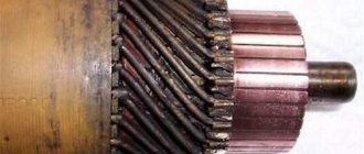
Generator circuit G-424: 1 - cover; 2 — oil seal; 3 - rotor; 4 - stator winding; 5 - terminal block; 6 — back cover; 7 — shield assembly; 8 - rectifier block; 9 - fan; 10 — protective casing; 11 - bearing.
Troubleshooting the generator
The method for determining the malfunction was as follows (I tried several methods, since replacing the relay regulator did not help):
Indirect determination of generator performance
This method does not allow you to accurately determine the malfunction of the generator, but it can still be used to determine whether the generator is “dead,” or there is still hope and the cause of the malfunction lies elsewhere.
Disconnect the wire from terminal “Ш” on the generator. And we apply + from the battery to this terminal, bring the wrench to the generator body, it should be magnetic, not much, but it is noticeable. If it is magnetic, then the rotor winding is working properly. Turn it off.
We connect a 12 volt lamp to the “+” terminal on the generator, and the other end of the lamp to ground. And we connect “+” from the battery to the “Ш” terminal. And we turn the engine with the kickstarter, the light should light up. If this happens, then the generator is working.
In my case, the light was on, I changed the relay-regulator, but the battery still did not charge, and when the engine was running, the red battery charge control light did not go out.
Cleaning and testing the generator G 424
- I removed the generator, unscrewed the back cover, pulled out the brushes - the wear was within normal limits, they were checked with a multimeter.
- I unscrewed the rectifier and it “ringed” like diodes, i.e. In one direction the arrow should deviate, I change the polarity, the arrow does not deviate. Those. the diodes are not “broken”, as they should be.
- I rang the stator windings - everything is normal, there is no short circuit to the housing.
Using the probes through the windows for the brushes with a multimeter, the armature rang - “it rang”, there is no short circuit to the generator housing.
Everything is in perfect order, the generator should be in good working order, so I didn’t completely disassemble it. But there is no charge. Therefore, I began to understand the operation of the relay regulator and look for the reason for it.
How to replace a faulty relay regulator on a scooter?
If the charging current is not supplied to the battery contacts when the generator is working properly, the stabilizer needs to be changed. Replacing it yourself is not difficult.
To do this you need to do the following:
- Place the scooter on the central support.
- Find the location of the device in a specific moped model. If you can’t find it right away, you can use the instruction manual.
- Dismantle the cladding. Depending on the moped model, the stabilizer may be located on the front (under the front plastic), in the rear, or under the seat. In this case, the underseat space is removed along with the seat.
- Unscrew the device from its seat while maintaining the fasteners. As a rule, the relay is attached to the scooter frame with a bolt, or less often with a self-tapping screw.
- Disconnect the connector and secure the new regulator with the fastener. The installed device must have a pinout and connector similar to the one replaced, and be suitable in terms of parameters for this particular scooter model.
- Connect the relay-regulator on the scooter to a standard connector and assemble the remaining spare parts in the reverse order of disassembly.