How to check the hall sensor on a scooter: photo and video instructions
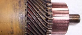
In addition, this sensor is present in brushed electric motors powered by direct current, and there it performs the function of determining the position of the magnet.
In the operation of a scooter, the relay regulator plays a very important role. In the diagram, the common wire is shown in green. In this case, engine operation is blocked.
The spark plug receives about 20 kW. If the spark on the scooter is lost So, knowing about the operation of the ignition system, you can easily identify the weak link. For example, if there is no spark in the system, the scooter stops and does not go further, through logical calculations you can find the reason, which is often associated with the hall sensor. Scooter Ignition System Components As with automotive systems, testing should always begin with the spark plug.
Hall sensor, checked with a multimeter.
It is unscrewed and inspected: The inspection process can be greatly simplified if you have a spare and working spark plug on hand. It is inserted in place of the old one, and the presence of a spark in the spark plug gap is checked. This is done by lightly touching a spark plug threaded into a wire to ground and simultaneously starting the engine.
You should always wear protective gloves when working, since 20 kW of current is no joke. It is prohibited to touch the body mass or spark plug with bare hands at this moment. The instrument panel should show voltage in the Volt region.
If this is so, then everything is in order with the switch, but if not, you need to check the functionality of the circuit going from the PCU of the engine control unit to the Hall sensor itself. The circuits are checked in the same way as is done on any household appliances - take a voltmeter, touch one probe to one end of the circuit, and the second probe to the other end.
If the voltmeter shows no voltage between these contacts, then the problem lies in this electrical circuit; the cable is broken, the insulation is broken, etc. When the serviceability of the circuits is checked, but the cause of the malfunction still remains a mystery, an element such as the engine control unit comes under suspicion.
In this case, it is necessary to check its performance by replacing it with a working part. Here we need a digital voltmeter - the resistance of the secondary winding is not high, and the pointer device will distort the data obtained.
If you short-circuit the probes of a digital ohmmeter, it will usually give a reading greater than zero. We remember how much it showed and subtract this value from the readings when checking the ignition coil.
The difference should be about 0. Connect the multimeter to the wire that goes from the switch block to the ignition switch. We turn the ignition key to position: So, we are left with an electromagnetic sensor and the supply winding of the generator.
Other answers in this thread
This is the sensor you are looking for. How to check the ignition sensor of a scooter?
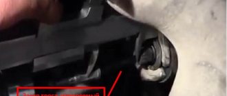
To begin with, I would like to make a small contribution to increasing the technical literacy of some people who are not particularly burdened with intelligence. And what’s funny is that the traders are there... How can you not go into the store: That’s where it comes from. Using a high-voltage wire, the ignition coil is connected to the A7TC 3 spark plug. On the scooter, the spark plug was cleverly hidden, and it can take quite a long time to find it the first time.
But if we “walk” along the high-voltage wire from the ignition coil, the wire will lead us straight to the spark plug cap. The cap is removed from the candle with a little effort.
Troubleshooting and repair of electrical equipment of the Delta moped
- The absence of a spark or its strength is not sufficient for ignition. To do this, unscrew the spark plug and evaluate its appearance. You should also check for a spark when turned out.
- When troubleshooting the ignition system, install a working spark plug and try to start the engine.
- Using a multimeter, check the contact between the motor and the frame.
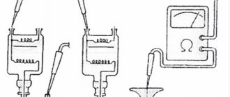
- The performance of the generator can be assessed by measuring the coil resistance. Resistance is measured between ground and a black wire with a red stripe. If there is no resistance or it is very low, the generator is to blame for the problem. To confirm this fact, you should dismantle the generator and check the resistance directly on the coil.
- If the generator is working, check the integrity of the circuit. The electrical diagram of the Delta moped allows you to determine the procedure for troubleshooting and troubleshooting.
- Then the resistance at the terminals of the ignition unit is checked. Since this element cannot be repaired, if problems are identified, it should be replaced.
There may also be problems with the battery charging system. A sign of problems will be a constantly discharged battery . The cause may be a malfunction in the power supply system. Problem identification is done using a multimeter.
If the power supply system is damaged, no current flows to the battery. Until the battery is discharged, the scooter will work, and then the engine can only be started by charging the battery or replacing it with a new one.
The electrical circuit of the Delta moped simplifies the troubleshooting process. When performing welding work, you should remember that without disconnecting the switch you can easily destroy all electrical equipment.
Modern scooters made in China have a similar layout. The engineers of the Celestial Empire did not bother and assembled all the critical components according to a single scheme. Even if there are differences, they are minimal.
This statement is also true for the electrical components of the moped. Any owner periodically encounters problems associated with these nodes. The electrical circuit of a Chinese 4t scooter is not a complex system; it contains only the main elements necessary for the full operation of the unit.
Knowing the main electrical wiring components and their purpose, you can quickly find the problem and fix it.
Causes and diagnosis of breakdown of position sensors
The cause of failure of Hall sensors can be:
- significant overheating of the electric motor – above 150–180 °C;
- mechanical damage;
- power surges;
- water getting inside the motor housing or throttle handle.
A clear sign of a breakdown of the Hall sensors is the twitching of the MK at startup while turning the throttle. To diagnose such a malfunction, a voltmeter is sufficient. It is also convenient to use a diagnostic tester to check the functionality of the motor wheel, controller or throttle grip. It allows you to diagnose position sensors and windings, identify existing defects, check the phase angle and the correctness of phase switching.
About adjusting the ignition of a 4t scooter
Knowing how to set up the ignition of a 4T scooter on your own, you can save time and money, since you will not need to contact a motorcycle repair shop. The procedure is simple, even if you have no experience it takes a little time, but you will need to be patient. Regardless of the type of ignition, an important role is played by how the marks are set.
Correct adjustment is a guarantee of stable and smooth engine operation even in cold weather conditions. Often, in used vehicles, the ignition is broken: this can happen for various reasons, ranging from elementary shaking when driving to improper handling of the equipment. In order for the scooter not to let you down and for you to be able to start it whenever you want, you will need to learn how to carry out this procedure yourself. To do this, you will need to have several keys that allow you to remove the valve cover if the engine is four-stroke.
Setting up the Vision scooter ignition system
If the ignition is knocked out, this may be the reason the scooter does not work. Restoring it is not difficult if you understand how it is done.
Advice: before starting work, carefully check and clean the carburetor: this may be the reason. Adjust the quality of the mixture. In addition, it doesn't hurt to check the spark plugs.
You need to start adjusting by setting the timing belt in the desired position. As a rule, there are marks on it for this purpose; they are set at the factory. The cylinder must be installed at dead center. The mark may be indicated by the letter T or another symbol. Now make sure that the mark installed on the rotor matches the mark found on the magneto. To do this, you need to gently press the kickstarter. The rotor can also be turned using your hands, but this is more difficult.
There are also marks on the timing star in the form of holes or dots; they must be set so that the largest hole is on top and located exactly in the center. The remaining points should be below and located horizontally opposite each other. Setting the ignition advance makes sense if you want to increase the engine's power a little and make it start easily. The adjustment will help make the spark plug produce a spark earlier than the standard time. That is, a spark will appear even before the piston reaches the dead center. In cold weather, a moped configured in this way will start better.
Read more: Carburetor DaAZ 2105 1107010 20 jets
In order to configure the scooter in this way, you will need to repeat the procedure described above. However, there is a difference: the marks should not coincide clearly, and not reach each other by about 0.5 cm. The main difficulty lies in connecting the marks.
VESKO-TRANS.RU
Scooter is a common vehicle today, it does not require much fuel but at the same time it does not provide the incredible speed with which you can transport your two-wheeled motorcycle brothers. This is a very specific type of transport that not everyone will choose. But all the people who love scooters are always passionate about riding them, they have a lot of fun, they also find them very comfortable. But with all this, not a single car is insured against breakdowns, including a scooter .
Malfunctions can be very diverse, but in this article we will talk about electronics, and more specifically, how to test a switch on a scooter. Naturally, if you have no idea what we are talking about, you should not immediately resort to tools. It's best to take a long, hard look at how the electronics are housed in the scooter, the difference between checking the shifter on a car versus a moped, and what you can do to check the electronics for damage and repair the vehicle. Overall, before you think about how to test a scooter shifter, you should understand what it is.
Switch and circuit diagram of the device
How to check the switch on a scooter if you don't even know what it is or where to look for it? That's why you should start small. The first thing you need to do is figure out what the switch is. It's actually quite simple because the switch is the element in the vehicle's electrical ignition circuit that generates a low voltage pulse that is sent to the ignition coil. Isolating the definition from the overall picture does not look very clear, so let’s look at the structure of the entire circuit.
Therefore, the main element here is the generator, which generates the operating voltage to operate the switch discussed in this article. As mentioned above, using a power generator, the switch generates a pulse to the ignition coil, not just a pulse, but a low voltage. The ignition coil, in turn, transmits a high voltage pulse at a certain point in time, which is transmitted to the spark plug. The spark plug is screwed into the cylinder head and, after receiving a high voltage pulse, ignites the combustible mixture, which drives the engine. Well, now you know how the circuit works in a car, which will allow you to better understand how to make a control switch on a scooter.
Malfunction
What prompted you to study the article on how to control switch on 4T scooter or any other common model? Chances are your car won't turn on, but you don't know what the problem is. The plugs may catch fire and the engine may stop. All of this may have a cause in the switch, or it may not. This is the main problem of the repair. You need to identify where the problem is in order to solve it.
Ignition setup steps
The first possible breakdown is checked with a stroboscope; to do this, you need to check whether there are measured risks in the ignition synchronization. Rarely does anyone have an expensive strobe light for free use, but if you have the opportunity to ask your friends for it, then it’s better to start working with this check.
In order to start checking the synchronization of the marks on the system, you need to thoroughly warm up the moped motor. There is no need to strain the moped too much.
Connecting a strobe
After this, you should connect the strobe. If the technician is working with the device for the first time, he must first carefully study the operating instructions. Two wires come from the device, one of which should be connected to the moped’s power supply, and the second induction wire is connected to the spark plug.
A simple strobe for setting up the ignition of a moped
As soon as a spark appears on the spark plug during startup, the bright light of the strobe will indicate this. Now you should direct this light that appears to the location of the measuring marks and see how they are located relative to each other. If everything is correct, the risks are exactly the same, then the setup went as expected, no further adjustment is required.
Adjusting the ignition timing
If the measuring marks are not synchronously coupled with each other, or they are not visible, then you will have to adjust the start of the moped. More precisely, you will have to adjust the ignition timing. Different models of Chinese mopeds may have different adjustment methods. Therefore, before starting work, it is necessary to study the documentation attached to the moped . Adjustments must be made in accordance with the instructions.
If it is not clear where these measuring marks should be located, you should carefully inspect the generator flywheel, as well as the flywheel housing, and they will immediately show up.
Further work requires a careful approach and strict adherence to safety measures, since you will have to inspect and adjust the system with the engine running.
Equipment Features
Let's return to the strobe light. To operate, you need a type of this device that is equipped with a special sensor for counting the rotation of the hot shaft - this module is worth paying attention to.
If a strobe light that does not have such equipment falls into the hands of a master, then it is necessary to slightly adjust the progress of the work. It is necessary to check the engine starting at idle speed. But there is also a nuance here - you should be sure that the idle speed works accurately.
Read also: Car wifi rear view camera
The result of the test should be a position of the measuring marks in which the ignition will work perfectly. Once such a situation has been identified, it must be set. Further adjustments to other parameters are not recommended.
Checking the serviceability of the DH accelerator
There are 3 wires from the controller to the speed control:
- black - “zero”;
- red - 5 V power supply;
- green - control signal coming from the speed knob to the controller (the voltage varies in the range 0-4.2 V, this indicator is affected by the angle of rotation of the accelerator handle).
To check the performance of the DCs located in the speed control knob, you need to use a voltmeter to measure the voltage of the red wire. We connect the positive terminal of the voltmeter to it, and the negative terminal to the black wire. If a voltage of 5 Volts is not observed in the diagnosed circuit, then the cause of the failure is not hidden in the accelerator. The controller may be broken, the current may not reach it, or the wiring connecting the controller and the throttle grip may be broken.
If the measuring device demonstrates the supply of current to the speed control handle, but when it is turned, there is no voltage on the green wiring, then the cause of the failure is at least one broken DC or the wires connected to it. We replace used components with new products.
Ignition circuit components
The ignition system is an important element in the operation of the entire scooter. The formation of a spark and a precisely calculated impulse that ignites the fuel depend on it.
The scooter ignition circuit includes many components that are responsible for a specific job.
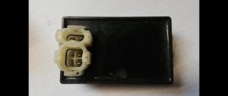
CDI ignition module
The first item in the list is the CDI module. This abbreviation stands for Capacitor Discharge Ignition - ignition from a capacitor discharge.
The switch module is made in a non-separable box, so if it fails, it is replaced with a new one. 5 wires are connected to it, distributed throughout the entire ignition circuit of the scooter.
Relay regulator
This is the same rectifier that converts alternating voltage to direct voltage, with a range of 13.5-14.9 V. C
.
The regulator is located under the plastic cover of the scooter at the front. It is attached to a metal backing for better heat dissipation.
The main circuits of the relay circuit are:
- The green wire is common.
- Red – output of converted and stabilized voltage within the established limits.
- White and yellow – AC input to the regulator. Due to electronics, the voltage is converted into powerful impulses. The yellow wire supplies power to a heavy load on the on-board network - headlights and instrument panel lighting.
The current for lamps is not stabilized, but is limited to acceptable values. At high generator speeds, the voltage goes beyond the operating ranges of the lamps, which leads to their burnout. The situation is very familiar to those who have encountered faulty relay regulators.
Because of one unit, you can lose all the light bulbs in a matter of seconds, so you should monitor the on-board voltage regularly.
Delta moped wiring diagram china
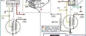
The electrical circuit diagram of Chinese scooters is shown in the figure:
As with other electrical connections, there is a common wire on all cube mopeds. In this diagram it is the negative tire running along the entire body. The corresponding battery terminal is also connected to the scooter's frame, ensuring that each electrical component's ground is in constant contact with the power source.
Electrics and electrical equipment of a scooter
The main components in the 4t moped circuit are:
- central locking;
- battery charging source – generator;
- voltage limiter;
- spark formation and control systems;
- control elements for headlights, brake lights, turns;
- fuel level indicator in the tank.
All circuits are connected together using wiring.
Depending on the modifications and dimensions of the scooter, the instrument panel may include a tachometer - a device for monitoring the number of engine revolutions.
All of the listed nodes of the general scheme perform a strictly assigned role. Failure of at least one of them leads to the cessation of operation of the connected devices. Therefore, monitoring the serviceability of the main elements must be done every certain period for the purpose of prevention.
Checking power on the switch
We connect the battery. Turn the ignition key. We measure the incoming voltage at the switch connector. 12 V should be supplied to the red wire from the battery through the fuses and the ignition switch. We set the device to V-20 V. We connect one probe to the green wire, the second to the c/h wire.
If there is 12 V, then on dio 34 we immediately check the voltage on the pink wire - it should be 9 V. This means that the electrical circuit from the battery to the switch is working.
Some older Japanese Suzuki and Yamaha models do not have a switch. The ignition coil operates directly from the pulse generator. Therefore, there is no need to check the voltage from the battery, but you only need to check the operation of the generator and rectifier (according to the diagram).
Egnition lock
This component in the circuit of a 4-stroke 50cc or 150cc moped represents a switch. Moreover, it is multi-positional.
The lock performs the task of a central switch. It turns off the power to the entire scooter and turns the circuit back on when you turn the key. The larva itself is connected to a slider, which closes the corresponding contacts.
In the first position, the main wires interact - red and black. Current from the battery is supplied to the main circuits of the scooter. Since then it has been ready to launch.
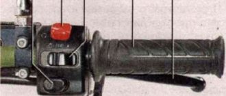
The remaining positions close the black and white wire from the ignition module to the ground of the scooter. The operation of the motor is blocked by interrupting the spark supply from the coil. Depending on the modification, some models have a stop button in the electrical circuit. It performs the same function as the lock.
Theory
Once upon a time, mechanical interrupters (contacts) were used in battery ignition systems. At the right moment, they opened the circuit in the primary winding of the ignition coil - the current disappeared, the effect of magnetic induction occurred and a high voltage was induced in the secondary winding of the ignition coil, which was supplied to the spark plug. And then, in the form of a spark discharge, it jumped between the electrodes of the spark plug, forming a spark that is well known to all of you.
In modern ignition systems, such as CDI, which is what we will talk about, the principle of spark discharge formation remains almost the same. With the exception of the method of controlling the moment of sparking.
general information
Consumer qualities
Buyers, first of all, are attracted not only by the fairly affordable price of mopeds of this brand, but also by:
- the ability to service the moped with your own hands;
- availability and availability of spare parts;
- ease of carrying out scheduled maintenance;
- Possibility of year-round operation.
Technical features
For convenience, technical information about the most popular moped from China is grouped into a table:
Chongqing Wonjan motorcycle China
For reference: the wiring of the Delta moped is designed for capacitor ignition. The photo below shows its schematic diagram.
Theory
Once upon a time, mechanical interrupters (contacts) were used in battery ignition systems. At the right moment, they opened the circuit in the primary winding of the ignition coil - the current disappeared, the effect of magnetic induction occurred and a high voltage was induced in the secondary winding of the ignition coil, which was supplied to the spark plug. And then, in the form of a spark discharge, it jumped between the electrodes of the spark plug, forming a spark that is well known to all of you.
In modern ignition systems, such as CDI, which is what we will talk about, the principle of spark discharge formation remains almost the same. With the exception of the method of controlling the moment of sparking.