The purpose of this article is to clearly show part of the operation of the on-board system of a motorcycle, which is fundamentally no different from auto wiring.
Diagrams with wire colors are usually intended to help troubleshoot problems and make it easier to find in an electrical circuit, but do not provide an understanding of how it all actually works. On such diagrams, instead of a relay, they draw a box with numbers, and this immediately limits people from using any other relay, even one that is not similar in appearance, in case of replacement. This point is fundamental, and therefore it is better and more useful to use a circuit diagram! In fact, electrical wiring can be read without colors through instruments. Below is a diagram without colors that clearly demonstrates the operation of the relay.
Relays with the same parameters may look different. From left to right, the first two are electromagnetic, and the last is semiconductor. The essence of the relay is one thing - switching power parts. But the conventional graphic designation of an electromagnetic relay looks like it is shown in the figure below. Conventionally, the graphic designation (UGO) emphasizes the principle of the relay on the circuit, and not its execution, and thus gives an idea of the operation in the circuit.
And the correct thing to do is to read circuit diagrams and think in the language of circuit diagrams. Since basic knowledge makes it possible to work with any material, but when drawing pictures with boxes you are limited to the appearance of the boxes. And since you don’t have a similar box, you won’t be able to do anything further.
Electrics and electrical equipment of a scooter
Dedicated to all owners of Chinese scooters...
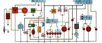
First, I would like to present a wiring diagram for a Chinese scooter.
Since all Chinese scooters are very similar, like Siamese twins, their electrical circuits are practically no different.
The diagram was found on the Internet and is, in my opinion, one of the most successful, since it shows the color of the connecting conductors. This greatly simplifies the diagram and makes it more comfortable to read.
(Click on the image to enlarge. The image will open in a new window).
It is worth noting that in the electrical circuit of a scooter, just like in any electronic circuit, there is a common wire . On a scooter, the common wire is the minus ( - ). In the diagram, the common wire is shown in green . If you look more closely, you will notice that it is connected to all the electrical equipment of the scooter: headlight ( 16 ), turn relay ( 24 ), instrument panel backlight lamp ( 15 ), indicator lamps ( 20 , 36 , 22 , 17 ), tachometer ( 18 ), fuel level sensor ( 14 ), horn ( 31 ), tail light/brake light ( 13 ), start relay ( 10 ) and other devices.
First, let's go over the main elements of the Chinese scooter circuit.
Egnition lock.
Ignition switch ( 12 ) or “Main switch”. The ignition switch is nothing more than a regular multi-position switch. Even though the ignition switch has 3 positions, the electrical circuit uses only 2.
When the key is in the first position, the red and black wires are connected. In this case, the voltage from the battery enters the electric circuit of the scooter, the scooter is ready to start. The fuel level indicator, tachometer, sound signal, turn relay, and ignition circuit are also ready for operation. They are supplied with power from the battery.
If the ignition switch malfunctions, it can be safely replaced with some kind of switch like a toggle switch. The toggle switch must be powerful enough, because the entire electrical circuit of the scooter is, in fact, switched through the ignition switch. Of course, you can do without a toggle switch if you limit yourself to short-circuiting the red and black wires, as the heroes of Hollywood action films once did
.
1 is shorted to the housing (common wire). In this case, engine operation is blocked . Some scooter models have an engine stop button ( 27 ) to block the engine, which, like the ignition switch, connects the white- black and green (common, body) wires.
Generator.
The generator ( 4 ) produces alternating electric current to power all current consumers and charge the battery ( 6 ).
There are 5 wires coming from the generator. One of them is connected to a common wire (frame). The alternating voltage is removed from the white wire and supplied to the relay regulator for subsequent straightening and stabilization. The yellow wire removes voltage, which is used to power the low/high beam lamp, which is installed in the front fairing of the scooter.
Also in the design of the generator there is a so-called hall sensor . It is not electrically connected to the generator and there are 2 wires coming from it: white- green and red - black . The hall sensor is connected to the CDI ignition module ( 1 ).
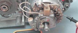
Relay regulator.
Regulator relay ( 5 ). People may call it a “stabilizer”, “transistor”, “regulator”, “voltage regulator” or simply “relay”. All these definitions refer to one piece of hardware. This is what the relay regulator looks like.
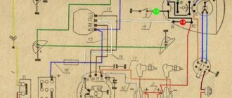
Alfa 110 moped wiring diagram
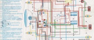
This abbreviation stands for Capacitor Discharge Ignition - ignition from a capacitor discharge. Sprinkle talcum powder on the inside of the tire. Electrical diagram of Delta 50 mopeds without a tachometer The photo below shows a schematic electrical diagram of the Alfa, Delta moped and other mopeds that do not have a tachometer.
Change the oil in the gearbox with a warm engine after the first km, and then regularly after km in the following order: remove the filler and drain plugs; drain the used oil; Screw in the drain plug and fill in approximately cm3 of oil; screw in the filler plug; let the engine run for 3-5 minutes, shift gears alternately.
When starting a cold engine, press the float stop 22 fig. Problem identification is done using a multimeter.
Place part of one bead of the tire in the recess of the rim, use a spudger and a wrench to push the entire bead of the tire onto the rim and slide it towards the rim flange.
Brakes To adjust the front brake, a stop is installed on the brake pad disc. Check the operation of the gear shift mechanisms, clutch, and brakes.
Protect the paper element from contact with oil and gasoline. Obe3obPasha Leave a comment Over the past few decades, the domestic moped manufacturer has completely left our market, and Chinese analogues and new models have taken its place. Electrical wiring for the 157QMJ engine (Simplified) or how to start the engine without a moped
Ignition circuit elements.
One of the most important electrical circuits in a scooter is the ignition circuit. It includes the CDI ignition module ( 1 ), ignition coil ( 2 ), spark plug ( 3 ).
CDI ignition module.
The CDI ignition module ( 1 ) is made in the form of a small box filled with compound. This makes it difficult to disassemble the CDI unit if it malfunctions. Although the modular design of this unit simplifies the process of replacing it.
There are 5 wires connected to the CDI module. The CDI module itself is located in the bottom of the scooter body near the battery compartment and is secured to the frame with a rubber clamp. Access to the CDI block is made difficult by the fact that it is located in the bottom part and is covered with decorative plastic, which has to be completely removed.
Ignition coil.
Ignition coil ( 2 ). The ignition coil itself is located on the right side of the scooter and is mounted on the frame. It is a kind of plastic barrel with two connectors for connection and a high-voltage wire output that goes to the spark plug.
Structurally, the ignition coil is located next to the start relay. To protect against dust, dirt and accidental short circuits, the coil is covered with a rubber cover.
Spark plug.
A7TC spark plug ( 3 ).
Service Features
Unfortunately, suppliers of motorcycle equipment do not always take into account the specific features of a particular type of vehicle, assuming that low price is more important. In particular, the majority of mopeds supplied to Russia under the ALPHA brand are not designed for our climatic and road conditions.
Original wiring diagram for an Alpha moped with 49 and 110 cc engines. cm
This manifests itself in the following:
- Most mopeds are used off-road (in rural areas, for trips to nature, fishing, etc.). And factory tires, alloy rims, springs and shock absorbers are not designed for such loads;
- The quality of gasoline and oil is also far from ideal, which affects the performance parameters of the moped;
- The moped is not intended for operation at sub-zero temperatures.
Advice: The wiring of the Alpha moped especially suffers from harsh climates, since its insulation is made of cheap plastic. At sub-zero temperatures it becomes brittle and breaks down. Experienced owners, after purchase, replace it with rubber-insulated wiring.
In the same way as wiring for an Alpha moped, other “diseases” of Alpha mopeds can be cured with the help of replacement. In particular:
- Factory tires are replaced with more wear-resistant ones;
- Alloy wheels are replaced by traditional spoked rims;
- Shock absorbers are reinstalled from domestic motorcycles.
Relay operating principle:
The correct diagram, which shows the meaning of using a relay, is presented below. By controlling the electromagnetic relay coil through key SA1 with low voltage and current, the relay closes a pair of contacts K1.1 and switches higher voltage and current to lamp HL1. Why is this necessary? It would seem, why not just use SA1 and a 12 volt battery, simply supplying current through it. Yes, everything is simple, in this way low-current circuits control power ones, while preserving the contacts of the SA1 switches from burning out and saving the power parts of the circuits (large cross-section wires, overall dimensions of products), the SA1 switch is not designed for power loads and higher voltages and is thus decoupled from the power part.
Now let's move on to the simplest circuit for a motorcycle, which you can make with your own hands. But first we need this very scheme! First, let's divide the motorcycle's electrical wiring into several nodes and describe them in a conventional graphic diagram. This diagram gives clarity to the whole picture. The blocks themselves are easier to consider separately.
Here is a graphical diagram of the components of the electrical circuit of the motorcycle as a whole. Let's look at the meaning and functions of blocks.
Blocks:
— Generator. — Rectifier block. — Voltage stabilizer (Regulator). - Power supply. — Fuse block. — Ignition control unit. — Electrical diagram of consumers (starter, light, repeaters, etc.)
A generator is a machine that converts mechanical energy into electrical energy. The generator is connected to the engine through gears, belts and other connections. During operation, the engine simultaneously rotates the generator, which in turn produces electrical energy. The generator can be either direct or alternating current. We will consider an alternating current generator.
Graph of alternating voltage versus engine speed. In simple terms, the faster the engine rotates, the more energy the generator produces.
Since the on-board network is designed to operate with direct current at a voltage of 12V, we need to rectify the current and stabilize the voltage.
The rectifier unit is a converter of the input electrical current AC to DC. Performed on semiconductor diodes.
Technologies do not stand still and in the photo above, on the left, there is a so-called “horseshoe” diode assembly used in generators, and on the right is a diode assembly of the same principle, but much smaller in size. Both can be used in circuits.
Voltage stabilizer (regulator) is an electromechanical or electrical semiconductor device that allows you to change the output voltage. The simplest meaning of the regulator is that while the voltage does not exceed 14V in the network, the regulator supplies voltage to the excitation winding of the generator; as soon as the speed increases, at which the voltage is above 14V, the regulator turns off the excitation winding and the generator stops generating energy and essentially spins in single. It is most likely not correct to call this system a voltage stabilizer, since it is not a stabilizer, but the point is to provide more or less stable on-board power.
In the photo above there is a relay-regulator, different in size and design. The first is electromechanical and large, the last two are more modern and electronic, made on a semiconductor element base.
The operation of the components: Generator, Rectifier, Relay-regulator was described in more detail in the article Restoration, testing, connection of the G424 generator
Power source - DC battery. First of all, it is required for the initial start of the engine and maintaining the on-board network within 12V at a time when the generator does not provide the required voltage during rotation. In fact, a running engine will work without a battery. While the generator provides the network with the necessary energy, the battery is charged.
Fuse box - provides protection for electrical circuits from short circuits. The essence of this block is a set of fuse links designed for a certain current. If the fuse is below the power consumption rating, it will blow and disconnect a section of the circuit from the on-board circuit. Therefore, the fuse must have a rating greater than the current consumed by the circuit in normal operation, and the rating must be such that in the event of a short circuit the fuse will burn out before the wiring.
You can also look at the fuse box here Fuse box
Well, now, let's look at the electrical circuit of consumers in more detail.