With the development of trade relations between Russia and China, in addition to traditional knitted goods and consumer electronics, various auto and motorcycle equipment began to be imported en masse to our country. And since the domestic motorcycle industry was experiencing a decline, the new items were to the taste of motorcyclists and began to be purchased en masse for their own needs.
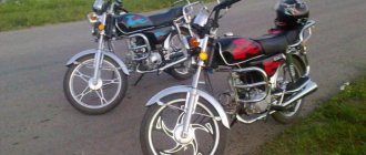
Classic look of the Alpha moped
Of particular interest is the ALPHA moped with an air-cooled engine, which is sold in the Russian Federation as “Alpha 110cc” or “Alpha 49”. The numbers in the name indicate the engine displacement:
- 49 cc four-stroke air-cooled engine. cm, power 4.5 hp;
- 110 cc four-stroke air-cooled engine. cm, power 7 hp.
Mopeds, due to their external resemblance to motorcycles, differ from scooters, although they represent a separate class. However, the combination of technical parameters, ease of do-it-yourself maintenance and low operating cost have made this moped a sales leader on the Russian motorcycle market.
For reference: in China, several manufacturers assemble the ALPHA model. Among them are Horse, Chong Qing Bull, WONJAN, Omaks and a number of others. Companies such as AVM and SMoto also assemble mopeds in Russia. At the same time, the wiring diagram of the Alpha moped is identical, regardless of the location of assembly.
Relay regulator
This is the same rectifier that converts alternating voltage to direct voltage, with a range of 13.5-14.9 V. C
.
The regulator is located under the plastic cover of the scooter at the front. It is attached to a metal backing for better heat dissipation.
The main circuits of the relay circuit are:
- The green wire is common.
- Red – output of converted and stabilized voltage within the established limits.
- White and yellow – AC input to the regulator. Due to electronics, the voltage is converted into powerful impulses. The yellow wire supplies power to a heavy load on the on-board network - headlights and instrument panel lighting.
The current for lamps is not stabilized, but is limited to acceptable values. At high generator speeds, the voltage goes beyond the operating ranges of the lamps, which leads to their burnout. The situation is very familiar to those who have encountered faulty relay regulators.
Because of one unit, you can lose all the light bulbs in a matter of seconds, so you should monitor the on-board voltage regularly.
What to do next?
Most likely, the ignition you assembled from a Java 634 scooter is rough and consists of twists, which is why you should replace them with normal terminals and twist the wires into braids. There is only a small matter left to do - completely replace all the remaining electrical elements, starting from the dashboard and ending with the head lighting and turn signals. Fortunately, now you have full 12 volts, so you can replace everything with spare parts from older models. On the other hand, 12 volts open up the opportunity to install almost any modern turn signal, high-quality lighting and many other useful devices such as a charger for a smartphone or an on-board audio system.
Generator and ignition sensor
You can check the generator and sensor without removing them from the engine.
We switch the tester to the AC measurement mode for the 2V range or, if your tester has such an option, for 200mV. With one probe we touch any metal part of the scooter or engine, with the other probe we touch the sensor wire (in the picture above it is labeled as a Hall sensor, but in fact it is an inductive ignition sensor). We turn the engine with the starter and look at the multimeter display. If the numbers are flashing on the display, it means the sensor is generating a signal and everything is fine with it. Otherwise, the sensor is faulty or the wire is broken.
Alteration work
Let's start working directly in Java.
The modification instructions will be as follows:
We fasten the faceplate with M6 bolts. We use only with flush-mounted heads, since regular bolts will interfere with the operation of the rotor.
Installing the faceplate
We install the rotor and check its rotation. It should rotate freely and without play on the axis.
If the faceplate is installed correctly, the rotor will rotate freely
- We clamp it together with the flange under the modulator using a bolt.
- We mount the stator. First, we remove the terminal of the center of the stator windings - it will be needed for the relay for the generator operation indicator lamp.
We bring out the terminals for connecting a car relay from a VAZ 2101 to a control lamp
- We connect the wires.
- Install the breaker plate.
Installation of the plate. This option is made with a Hall sensor
That's all. All that remains is to check the functionality of our modernization, for which we start the engine with the cover removed. If necessary, set and adjust the ignition angle.
Characteristics
The Alpha 110 motorcycle can be used both for riding on city streets and for long trips in the countryside.
Alpha. 2022 model
The latest Alpha model, which left the factory in 2022, received a number of updates:
- a quieter muffler, although many “alfists” for some reason, on the contrary, try to give the muffler more roaring sound;
- higher quality, grippy rubber;
- the updated speedometer-tachometer panel is a real gift for mopedists, since the design of the double aluminum can is already pretty boring;
- more contrasting colors of the motorcycle;
- Availability of new generation safety bars.
Do-it-yourself IZH Jupiter-5 engine tuning
Almost all motorcycle owners begin their transformation with a muffler. Installed chrome “cans” can add solidity, but will “strangle” the engine. Therefore, with such an upgrade it will be necessary to change the intake. A correctly configured resonator, which has a separate muffling part, will allow the engine not only to “breathe” freely, but also, when operating at certain speeds, it will be able to provide pickup.
For “Jupiters”, in which the cubic capacity of each cylinder is 175 m 3, tuned resonators from motorcycles from the Kovrov plant are ideal. Here everything depends on your desire - if you want it to “shoot” at the top, then the resonator from the SMB-2 will suit you, the power in the “middle”, then the resonator from the ZiD-200.
Ignition circuit components
The ignition system is an important element in the operation of the entire scooter. The formation of a spark and a precisely calculated impulse that ignites the fuel depend on it.
The scooter ignition circuit includes many components that are responsible for a specific job.
CDI ignition module
The first item in the list is the CDI module. This abbreviation stands for Capacitor Discharge Ignition - ignition from a capacitor discharge.
The switch module is made in a non-separable box, so if it fails, it is replaced with a new one. 5 wires are connected to it, distributed throughout the entire ignition circuit of the scooter.
The block is hidden inside the scooter, so getting to it is not easy. The plastic covers will have to be completely dismantled.
Ignition coil
The purpose of this component is a fast pulse of high voltage voltage based on a signal from the switch. It goes directly to the spark plug, where it is converted into a spark.
The coil is located on the right side of the Chinese scooter and is attached to its supporting structure. It is easy to recognize - it is made in the form of a plastic barrel. On the reverse side there is a thick wire connected. It is he who transfers the discharge according to the circuit from the transformer to the spark plug.
To protect against dirt and dust, the coil is placed in a rubber cover.
Spark plug
Its function is simple - to form a spark and ignite the mixture inside the cylinder. The scooter uses an A7TC spark plug.
Its position is hidden from view, but experienced owners know where to look for it. Having passed along the high-voltage wire, we reach the engine block and the spark plug cap.
The rubber seal protects the contact from accidental electrical breakdown. Remove with a little effort towards you. Do not pull the wire too hard - the cap may come off.
The spark plug is unscrewed with a socket wrench. After removal, you need to inspect the color of the contacts and their condition. An indicator of good engine performance is a brown tint without traces of soot. Deviation from the norm indicates a malfunction of the carburetor.
Starter
The device is used to make it easier to start a scooter engine, without using a kick pedal. The starter is located in the middle part of the moped, near the engine. To open it, you need to remove the decorative plastic.
The starter is connected through the starting relay, which is located on the scooter frame.
Fuel gauge and indicator
The sensor measures the amount of gasoline in the tank and signals the need to refuel. It is located in the tank itself and is connected by three wires.
The indicator is directly connected to the sensor. Both are powered by stabilized current from the rectifier. If problems are observed in the operation of the indicator, you should check the connection to the circuit.
Voltage is supplied only when the ignition switch is turned on.
Turns relay
The breaker is used to control the turn lights. When the button is closed, the relay produces current pulses with a frequency of 1 Hz.
The block is located under the instrument panel. To change the relay you need to remove the plastic protection.
Switching the circuit is not difficult. When turning right, voltage flows through the blue wire, which is responsible for the corresponding lamps. The left position of the switch shorts the gray bus to the orange one.
Duplicate lamps on the instrument panel are connected in parallel to the turns circuit lines. They signal that the lamps are on on a specific side of the scooter.
Sound signal
The purpose of the sound horn is clear to everyone. On the scooter it is located near the limiter relay.
The signal is powered by direct current through the ignition switch and is activated by a button on the handlebars of the moped. The component is non-separable, so if it fails, it is completely replaced.
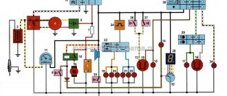
Electrical circuit diagram of the IZH Planet Sport motorcycle
I — parking light lamp; 2 — main light lamp; 3 — neutral control lamp; 4 - resistor; 5 — oil pressure control lamp; 6 — direction indicator relay; 7 — diode block (isolation); 8 — lamp for illuminating the speedometer scale; 9 — ignition switch; 10 — front direction indicator lights; II - headlight switch and emergency ignition switch; 12 — handbrake brake light switch; 13 — relay-regulator; 14 — neutral lamp switch; 15 — high beam control lamp; 16 — turn signal control lamp; 17 — lamp for monitoring generator operation; 18 — sound signal; 19 — light switch and direction indicators, horn switch; 20 — spark plug; 21 — ignition coil; 22 — foot brake brake light switch; 23 - generator; 24 - battery; 25 - fuse; 26 - rectifier; 27 — oil pressure sensor; 28 — rear direction indicator lights; 29 — rear light.
While improving the car, the plant made a number of changes to it. In particular, the fixation and clarity of operation of the IZH P101 and IZH P102 switches and the switch on the steering wheel have been improved. The optical element in the headlight was replaced by the Soviet FG 137, and the IZH UP1 turn signal lights were replaced with standardized lights 16.3726. There are other innovations as well.
Jupiter-4 is now equipped with 12-volt equipment. The plant is also preparing for production a new Planet-Sport model, the electrical equipment of which is unified with Jupiter-4.
However, even now, Planet-Sport owners can use a number of IZH Yu-4 electrical appliances without significant modifications. These include generator 28.3701 (if it is sold without a breaker and capacitor, they can be taken from the old IZH GP1); direction indicator lights 16.3726; headlight optical element FG 137; rear light FP146; speedometer SP102; battery 6MTS-9.
To install the IZH RP2SM-10 turn signal breaker in the headlight housing, you need to make an additional bracket from a steel strip 1-1.5 mm thick and replace the plug tips with round ones. After the same modification of the tips, the combined switches IZH P101-20 and IZH P102-20 from the IZH Yu-4 motorcycle can be used on Planet-Sport. To do this, squeezing out the fixing tendrils with an awl or knitting needle, remove the plug tips. They cut them off and crimp and solder round tips on the stripped ends of the wires. At the IZH P101-20 switch, a blue outlet wire 130-150 mm long with a plug tip is soldered to the black wire.
Improvements in the electrical equipment of motorcycles and the use of new devices have naturally led to some complication of the electrical circuit. Let's get acquainted with its main elements using the example of electrical equipment of the “Planet-Sport” circuit, which is in many ways similar to the circuits of other Izhevsk motorcycles.
. This is perhaps the main system, because without it the motor cannot work. Let's trace and remember its electrical circuit. From the battery 24 through fuse 25 and rectifier 26, power is supplied to terminal (2) of the connecting panel in the headlight housing and then to terminal (3) of the ignition switch 9. When the key is turned to position I, the terminals (3—2—1 and 5) are closed -6). Now from terminal (1) of the lock, the current flows to terminal (5) of the connecting panel, from it to the emergency ignition switch 11, and through its closed contacts to terminal (1) of the connecting panel and then to the primary winding of the ignition coil 21 (the second end of the primary winding — terminal “—” is connected to the breaker). This turns on the motorcycle's ignition circuit.
If the engine does not run due to lack of spark at the spark plug, check whether high voltage is supplied to it. To do this, remove the wire from the cap and bring it to the edge of the cylinder with a gap of 2-3 mm. If, when the crankshaft is rotated by the kick starter, a spark does not appear between the wire and the cylinder, there is no high voltage. The reason for this is found as follows. When you turn on the ignition, use a 12-volt test light to check whether power is supplied to the “+” terminal of the ignition coil. If not, then check the entire circuit, starting from the battery. The usual cause of no voltage is loose or oxidized terminals, or a faulty fuse.
Having ensured that normal voltage appears at the “+” terminal of the ignition coil, carefully clean the breaker contacts, check and set a gap of 0.4-0.6 mm between them and adjust the initial ignition timing.
If the engine produces only isolated flashes when starting, and a white coating appears on the contacts of the breaker, it means that the capacitor has failed (rarely, but it happens).
With the correct gap, clean contacts of the breaker and a working capacitor, the reason for the lack of a spark on the spark plug may be a malfunction of its plastic cap (ground fault) or the ignition coil (it is non-separable, so it must be replaced). A poor-quality spark plug can cause engine interruptions or make it difficult to start. Signaling and lighting system
. When the ignition is turned on (key in position I), electricity from the battery 24 (or rectifier 26 when the engine is running) is supplied through terminals (3 and 1) of the ignition switch 9 to terminal (5) of the connecting panel. The power wire for turn signal relay 6, horn 18 and the “positive” wire for light switch 11 located on the steering wheel are connected to it. From relay 6, power is supplied to the lights through the terminal (9) of the connecting panel and then to the turn signal switch 19. From it, through terminals (6 and 7) of the connecting panel, it goes to lights 10 and 28 turn indicators. The turn signal indicator lamp 16 is also connected to the terminals (6 and 7) of the connecting panel through the diode block 7.
The reason for the failure of direction indicators to work most often is the lack of “ground” in the lamps when their fastening to the frame is loosened, oxidation or loosening of the connections of the tips with the wires, contacts in the lamp sockets.
To speed up troubleshooting, the circuit is checked from the non-working consumer to the power source. To determine the functionality of the turn signal relay 6 without dismantling it, you must first make sure that voltage is supplied to terminal (5) of the connecting panel and that the brown wire of the relay is securely connected to ground. Then check the serviceability of the circuits going to the direction indicator lights by connecting terminal (5) with terminals (6 and 7) of the connecting panel with a separate wire. The lights on the right (terminal 6) or left side (terminal 7) and indicator lamp 16 should light up without blinking if the circuits are working. Next, disconnect the pink relay wire from terminal (9) and connect it to terminals (6 and 7) on the connection panel. If the relay is working properly, the starboard or port side lights should blink at a frequency of 60 to 120 per minute.
The relay removed from the motorcycle is checked using two A12-21-3 test lamps (each with a power of 25 W), connected in parallel. Connect the “plus” of a constant voltage of 12 volts to the red wire, the “minus” to the brown wire, and the control lamps to the pink wire. When the device is working properly, the lamps should flash at a frequency of 90 ± 30 per minute.
. It contains the main part of the wiring diagram, the turn signal relay, the neutral 3 and oil pressure indicator lamps 5, the lamp 8 that illuminates the speedometer scale, the parking light lamp 1, the head light lamp 2, the ignition switch 9 and the speedometer.
On the latest motorcycle models, the turn signal switch is mounted on the frame under the gas tank.
Let's consider the electrical circuit of the head, parking and side lights. When the ignition is turned on (key in position I), power is supplied to terminal (4) of the connecting panel, then through the contacts of the light switch 11 - to the central contact of the high-low beam switch 19. Next, through the terminals (11 and 12) of the connecting panel - to the high or low beam filament of lamp 2.
The side light in the headlight (lamp 1) and in the rear lamp 29 lights up when switch 11 is activated and current flows through contacts (5 and 6) of ignition switch 9.
If the ignition key is turned to position II (parking), then these lamps receive power through its contacts (3 and 5) regardless of the position of the switches on the steering wheel.
Lamps that glow dimly when the engine is not running indicate that the battery is not fully charged. If this is observed in all modes of engine operation, it means that the voltage in the lamp power circuit drops significantly. In this case, check the electrical connections of the power and ground wires, clean and tighten the screw and plug connectors, contacts in the headlight and flashlight lamp sockets. Check the serviceability and reliability of the contacts in the switches and fuse.
Since the motorcycle is constantly being improved during the production process and its electrical circuit is changing, it is advisable to include the differences in your motorcycle in the circuit printed here so that, using it, you can always easily and quickly find the desired circuit and determine the malfunction.
V. SAMOILOV, engineer Izhevsk
While easily fixing mechanical failures, motorcyclists experience difficulties if the electrics fail. It’s completely in vain, the wiring diagram of the planet Izh 5 is not complicated, it’s easy to figure out.
There is no need to have special stands and equipment for repairs. A minimum knowledge of electrical engineering and a simple avometer (tester) is enough; even often you can get by with just a test lamp.
We will tell you in more detail about the main electrical wiring components and possible malfunctions. The Izh Planet wiring diagram makes it easy to find a broken wire or damaged insulation (for example, a bad contact always gets hot).
But pay special attention to the fact that the electrical circuit is designed not only for 12 volts, there is also a high-voltage cable (connecting the coil and the spark plug), which cannot be checked with a regular ohmmeter.
In this case, we look to see if there is a spark at the coil output and at the output at the spark plug contact. Let's take a closer look at the main wiring components of the Izh Planet.
Electrics and electrical equipment of a scooter
Fuel gauge and indicator. The speed at which switching from later to earlier ignition occurs depends on the stabilization voltage of the zener diode, so it can be adjusted within a wide range, changing the stabilization voltage from 3.3 to
The difference between them is the number of wires wound and the colors. It is not electrically connected to the generator and there are 2 wires coming from it: white-green and red-black.
In order not to confuse it with another wiring element, we are looking for a spare part with ribs, since the relay-regulator requires cooling and they will definitely be on the metal case.
This is what the relay regulator looks like. This is the main task of this voltage regulator relay. Need to try.
Read additionally: Logbook of fuel and energy resources
After the turn relay, the turn signal switch is installed. I can’t say about the polarity of the pulses. It is shown simplified, but sufficient to understand the principle of its operation as part of the system.
Also connected to the regulator is a yellow wire coming from the generator. There are 5 wires connected to the CDI module.
According to the diagram, this is the right position. When selecting, it is necessary, as already mentioned above, to use zener diodes with a direct current-voltage characteristic, like a conventional diode. Serves to control the front and rear turn signal lamps. The difference between them is the number of wires wound and the colors.
The starter is used to start the engine. This relay is very similar to the Minsk or Voskhod motorcycle switch. Electrical wiring Alpha, Delta
https://youtube.com/watch?v=yRqZ2FeLb8I
Calculation and production of a resonator in reality 350 638
L=((118+164)/720*1/5250*3360)/2=1.24m = 1240mm
The length of the elbow should be within 20-28% of the total length of the exhaust system: (1240*28)/100 = 350mm The length of the straight cone should be 32-38%: (1240*32)/100 = 400mm The length of the middle part is accordingly 8 -10%: (1240*10)/100 = 120mm The length of the reverse cone is respectively 30-35%: (1240*30)/100 = 370mm The diameter of the elbow is 63-70% of the diameter of the cylinder, which is 58mm: (58* 65)/100 = 38mm , i.e. corresponds to the diameter of a standard JAVA elbow. The diameter of the muffling part is 65-75% of the diameter of the elbow, i.e. 25-28.5mm We will calculate the diameter of the middle part using the formula given in the article: 38+0.21*400 = 120mm
Why is it worth changing the electrical connections of the Alpha, Delta ignition
The need to replace individual elements of Alpha and Delta electrical wiring can be caused by various reasons. For example, your model was sold without a tachometer, but you want to install it. Or the wires responsible for connecting the ignition, starter, lighting devices and illuminating the indicators on the control panel have failed. There is also another reason why many drivers change not individual wires, but all electrical connections as a whole. This is due to the fact that even mopeds produced at domestic factories are not designed for operation in Russian climatic conditions. The cheapest plastic is used as insulation. Of course, this has a positive impact on the final cost of Alpha, Delta. However, at sub-zero temperatures, such insulation becomes brittle and begins to crumble. If you plan to use the moped in the cold season, it is better to immediately replace all electrical wiring with a better one. Moreover, this is not very difficult to do if you have certain skills, as well as a detailed diagram of connecting various wires.
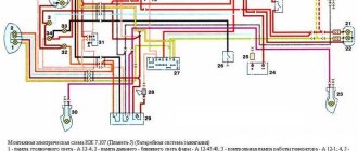
The electrical connections of a moped can seem complicated and confusing unless you study the theory first. In this case, we offer for your reference the official wiring diagram for “Alpha” and “Delta” mopeds with an engine from 49.9 to 107 cubic centimeters.
Since this diagram is in color, you can easily determine where the blue, yellow, green, pink and black-red wires are connected. If you have a brand new moped, all wiring will fully match this color scheme. It's another matter if your vehicle has already been repaired or upgraded. Then you will have to focus on the location of the wires, as well as the devices connected to them. For example, the starter switch is powered by pink and black wires, and the ignition switch is powered by green, black, red and black and white.
Features of electrical equipment
Unlike domestic motorcycles and mopeds, Alfa already in its basic version has a number of advantages:
- Electronic 12V ignition;
- Electric starter;
- Electronic tachometer on the instrument panel.
Wiring on an Alpha moped with an electronic switch in the ignition system
For reference: electronic ignition ensures trouble-free engine starting and stable operation in all operating modes. A simple circuit and the ease of replacing failed components with your own hands greatly simplifies the use of the vehicle.
Energy sources
The moped uses a circuit with a battery power source. The manufacturer does not recommend its operation without a battery, and the wiring diagram for the Alpha moped is additionally equipped with a relay regulator (see also the wiring diagram for UAZ 31512).
The wiring to Alpha is protected from voltage surges
The six-coil generator also copes well with its duties:
- Maintains voltage throughout the entire engine speed range;
- Ensures that the headlights and headlights work while driving.
For reference: the factory instructions do not allow the installation of additional lighting fixtures. It is also prohibited to use headlight lamps on a moped that exceed the power specified in the technical documentation.
Control and management bodies
The presence of informative devices makes the operation of the moped quite simple, which attracts many buyers. Moreover, which is typical, a fairly large number of beginners decide to buy a two-wheeled vehicle, choosing Alpha mopeds.
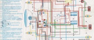
Wiring diagram for an Alpha moped with an electronic tachometer
The equally simple operation of the moped also contributes to its popularity. All the main functions of the vehicle are displayed on the steering wheel, and their status is displayed on the instrument panel:
- Speed mode;
- Engine speed;
- Battery charge state;
- Daily and total mileage (see also Ural motorcycle wiring diagram).
Photo of the instrument panel on the Alpha moped
Relay regulator for a moped using a triac
Hello friends. I recently bought myself another Alpha 110cc moped, let’s just say I bought it as scrap metal for a pittance. And an important problem in it is the lack of normal light, the relay regulator is faulty and the voltage is too high, which in turn burns the lamps. But the other day I bought myself 18W LED lamps from China and now I need to make some kind of regulator so that the voltage is normal. This is what I'll do. I once tried to assemble a regulator using thyristors, but the circuit was complex and unreliable, so I decided to try a simpler option. There are a lot of diagrams on the Internet, but even here I improved it a little, by the way, not in vain. I added a capacitor with a ballast resistor, and also added a current-limiting resistor on the control electrode of the triac. As you can see, all that is needed is a diode bridge, a triac, two zener diodes, a capacitor and two resistors. The bridge took 1000V 50A, the triac chose 25A TS122-25
Tags: homemade silencer Planet 5
Comments 29
and what about the sound, where is the video?!
yes there is no video, the sound is a little clearer than the original and louder)
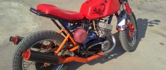
no offense, but this guy's look is just terrible
Well, what if it’s already 20 years old, your friend wants to convert it into a chopper in the spring, I’ll help, post photos as soon as possible
so Kent and I collected from a pile of garbage! =)) we got into our hands a frame on wheels, a rusty tank and a motor in a bag without a cylinder and a shaft elbow =)))
Well, I was the first to watch it)
Damn, I’m wondering why and when I signed up for this amazing thing =)))
plus to my colleagues. The resonator at 2T is an important thing and needs to be calculated.
except for the appearance - natural stupidity. In old motorcycle magazines, I don’t remember the number, there was an article about calculating the resonator of a two-stroke bike, I advise you to look for this article.
on the 5th planet, the welded resonator should ideally be 1.5 meters long) but how to put it there is another question, so you shouldn’t touch it, it was a drain plug)
Yes, it's just a change in appearance and nothing more, my friend said I did it. I plan to bring the resonator to the top in Minsk like on a cross-country, we’ll think about it there!
there is no traction there, read the theory of a 2-stroke engine
I agree, a 2-stroke motor needs a tuned resonator, which is designed for a specific motor. Even the native P5 had more or less... What is the current consumption?)))
You’re right, at one time I was involved in boosting Soviet motorcycle technology, even now the fallen Jupiter is in the garage)))
Well, bae, only the shape has changed and probably the sound. The craving rather dropped.
traction is a plus) since the racket is cut and the release is 2 times easier
Not to be confused with a four-stroke. Here the effect is the opposite.
I did it as a friend told me in a nutshell)
Not to be confused with a four-stroke. Here the effect is the opposite.
I don’t understand at all if someone says that 2-stroke bikes without a silencer are worse. Why don’t I smoke it? After all, the exit is free, it’s easier to free the camera. please tell me.
Source
Moped maintenance
Like any vehicle, Alpha mopeds require routine maintenance, the essence of which boils down to:
- Replacement of parts and assemblies whose service life has expired;
- Setting up and restoring the factory parameters of the main components and assemblies;
- Visual inspection of the moped to identify damage.
Chinese engines quite confidently “maintain” 20,000 km on our domestic fuels and lubricants without breakdowns or overhaul of the piston group. The main thing is to change the oil in a timely manner, especially during the break-in period.
If you do not operate the moped in harsh conditions (winter, cross-country racing, etc.), then all oil seals and rubber seals will also last a long time.
Tip: Change your air filter often. This will save the carburetor and make it easier to start the engine in all operating modes.
Causes of malfunction
The Chinese Alpha moped, whose price is affordable, does not cause owners many problems. Interruptions in a moped engine have several causes, and once you understand them, you can quickly fix the breakdown.
Disassembling the moped engine
So, if the engine starts with great difficulty, the muffler “shoots”, and smoke comes out of the chimney, it means that the moped is “capricious” due to problems with the carburetor. In order to solve this problem with the Alpha moped, you need to:
- clean the carburetor;
- thoroughly clean the moped's air filter;
- tighten the screws;
- adjust the moped carburetor.
If the Alpha slowly picks up speed, and its engine is not able to develop the declared power, then the reason is the incorrect operation of the moped valves. It can also “get sick” due to gaps and incorrect timing. In order to make the Alpha moped function normally, it is necessary to replace the used valves with new ones.
If the Alpha moped is not able to reach the required speed, despite the roar of the engine and solid revolutions, it is impossible to stop the spinning wheel, and gear shifting occurs intermittently, then the cause of the malfunction is clutch wear.
Moped clutch parts
To eliminate the breakdown, you must perform the following manipulations:
- remove the engine;
- remove the plastic cover;
- unscrew the tightening screw;
- Unscrew the adjustment mechanism and tighten the screw tightly;
- start a moped;
- turn on first gear and drive a few meters.
Another cause of moped engine malfunction may be wear on the drive sprockets. If they are very worn, they must be replaced with new ones.
You may encounter the problem of engine overheating. The situation can be corrected after adding oil. If oil leaks, you must immediately contact a professional service.
Alpha moped engine overheating
Engine disassembly
Disassembling the Alpha engine is quite simple. To do this you need:
- “arm yourself” with a key;
- Unscrew the bolts on the intake manifold (by 10);
- unscrew the cylinder covers and the bolts located there (4 pieces);
- remove the cylinder head.
After performing the necessary manipulations, you need to properly assemble the engine, installing all the parts in place.
A diagram can help you understand the nuances. Also, a lot of useful tips regarding repairing the most important “organ” of the Alpha moped are contained in the training video.
Making a resonator in real life 350 638
Dimensions of resonator parts designed for different speed ranges of the JAWA 638 motorcycle
Program for calculating resonators in Java, etc. download
1 way. A more labor-intensive method is to shorten the elbow according to its estimated length, and make the straight cone curved, dividing it into small cones. Photo of the resonator below:
Method 2. Less labor-intensive - we shorten the elbow so that a straight cone can be attached to it. Then we make several longitudinal cuts from the end of the knee to the place where the calculated knee should end.
The cut parts must be expanded so that they form the beginning of a straight cone. You will also have to cut “patches” to connect the cut parts. Photo of the resonator below:
You can scan metal using the setup-cone program. Download
Ignition circuit components
The ignition system is an important element in the operation of the entire scooter. The formation of a spark and a precisely calculated impulse that ignites the fuel depend on it.
The scooter ignition circuit includes many components that are responsible for a specific job.
CDI ignition module
The first item in the list is the CDI module. This abbreviation stands for Capacitor Discharge Ignition - ignition from a capacitor discharge.
The switch module is made in a non-separable box, so if it fails, it is replaced with a new one. 5 wires are connected to it, distributed throughout the entire ignition circuit of the scooter.
The block is hidden inside the scooter, so getting to it is not easy. The plastic covers will have to be completely dismantled.
Ignition coil
The purpose of this component is a fast pulse of high voltage voltage based on a signal from the switch. It goes directly to the spark plug, where it is converted into a spark.
The coil is located on the right side of the Chinese scooter and is attached to its supporting structure. It is easy to recognize - it is made in the form of a plastic barrel. On the reverse side there is a thick wire connected. It is he who transfers the discharge according to the circuit from the transformer to the spark plug.
To protect against dirt and dust, the coil is placed in a rubber cover.
Spark plug
Its function is simple - to form a spark and ignite the mixture inside the cylinder. The scooter uses an A7TC spark plug.
Its position is hidden from view, but experienced owners know where to look for it. Having passed along the high-voltage wire, we reach the engine block and the spark plug cap.
The rubber seal protects the contact from accidental electrical breakdown. Remove with a little effort towards you. Do not pull the wire too hard - the cap may come off.
The spark plug is unscrewed with a socket wrench. After removal, you need to inspect the color of the contacts and their condition. An indicator of good engine performance is a brown tint without traces of soot. Deviation from the norm indicates a malfunction of the carburetor.
Starter
The device is used to make it easier to start a scooter engine, without using a kick pedal. The starter is located in the middle part of the moped, near the engine. To open it, you need to remove the decorative plastic.
The starter is connected through the starting relay, which is located on the scooter frame.
Fuel gauge and indicator
The sensor measures the amount of gasoline in the tank and signals the need to refuel. It is located in the tank itself and is connected by three wires.
The indicator is directly connected to the sensor. Both are powered by stabilized current from the rectifier. If problems are observed in the operation of the indicator, you should check the connection to the circuit.
Voltage is supplied only when the ignition switch is turned on.
Turns relay
The breaker is used to control the turn lights. When the button is closed, the relay produces current pulses with a frequency of 1 Hz.
The block is located under the instrument panel. To change the relay you need to remove the plastic protection.
Switching the circuit is not difficult. When turning right, voltage flows through the blue wire, which is responsible for the corresponding lamps. The left position of the switch shorts the gray bus to the orange one.
Duplicate lamps on the instrument panel are connected in parallel to the turns circuit lines. They signal that the lamps are on on a specific side of the scooter.
Sound signal
The purpose of the sound horn is clear to everyone. On the scooter it is located near the limiter relay.
The signal is powered by direct current through the ignition switch and is activated by a button on the handlebars of the moped. The component is non-separable, so if it fails, it is completely replaced.
Major problem with motorcycle wiring
On IZ Jupiter 5, the wiring had a large number of contact terminals. Therefore, the main cause of malfunctions in the electrical circuit was a violation of the integrity of the connections. This led to such moments as: there is no charging for the battery, the generator does not provide the necessary 12-volt voltage to the system, the switch is not able to generate the necessary charge for the ignition coil, loss of functionality of all lighting devices, and a number of others.
The cause of loss of connection in the terminals was contamination and oxidation of the contacts. This was especially true for motorcycles produced at the beginning of mass production. The main way to solve this problem was to exclude these terminals from the IZ Jupiter 5 wiring.
To do this, we used soldering the wires directly to each other (by analogy with), as well as sealing the terminals on the supply wires to the following main elements:
- battery;
- generator;
- coil and spark plug;
- switch;
- lighting devices.
This increased the reliability of the connections and, as a result, ensured the operability of the specified parts, and also made it possible to turn on charging for the battery in order to subsequently confidently start the engine of the IZH Jupiter 5 motorcycle.
“Planet-Sport” is the first Izhevsk motorcycle with 12-volt electrical equipment, which meets all modern (as of 1982) requirements for this system.
(click on the picture to enlarge)
Chinese mopeds
Single platform models
Today's realities are such that you can no longer see domestic models on public roads.
Times are changing, and the weakened banner of freedom from the hands of the domestic “Carpathians” and “Verkhovyna” was picked up by Chinese moped series: Let’s state the fact - products from China have become mass in the domestic motorcycle market
- Alpha;
- Delta (DELTA);
- Dino;
- Irbis;
- Viper (VIPER);
- Zip Star;
- Leader;
- Mustang;
- Breeze;
- Dingo;
and other similar models, equipped with everything necessary for travel. These are all Delta “co-platforms” produced by the Chinese manufacturer Chongqing Wonjan motorcycle and the companies that bought a license from it.
Similarity of design
It is noteworthy that the electrical wiring of the Delta moped is similar to other models, which facilitates maintenance and increases the popularity of vehicles. Although seemingly complex at first glance, the electrical connection diagram is quite traditional
The video in this article will provide information regarding maintenance of similar models. For products with an instrument panel containing a tachometer, we publish part of the diagram, which also has differences in the controls. In this case, the wiring for the Delta moped is supplemented with several elements for connection. The photo shows part of the electrical circuit of the Delta model with a tachometer
Signs that adjustment is needed
Based on certain signs that appear in abnormal engine operation, we can conclude that the carburetor needs adjustment.
The list of deviations is quite wide:
Do-it-yourself carburetor adjustment for VAZ 2107
- the power plant does not develop the required power under load;
- when the scooter accelerates sharply, failures in engine operation are felt;
- a cold engine is difficult to start with the starter after a long period of parking;
- the scooter's power unit consumes fuel in increased quantities;
- there is no quick response of the engine to a sharp turn of the accelerator handle;
- The engine may suddenly stop due to insufficient fuel mixture.
The carburetor should be adjusted if there are signs that adjustment is necessary.
Ignition coil
If everything looks intact, check the ignition coil. To do this, disconnect it (remembering how the wires are connected) and use a multimeter to check the resistance of the windings.
The primary winding is made of thicker copper wire. Its terminals are connected to two terminal connectors at the end of the coil. It has a small number of turns and therefore its resistance is low, approximately 0.5-5 Ohms. One wire of the coil is connected to ground - you need to check it, attach one multimeter probe to the nearest metal part of the moped, and the second to the coil connector. The resistance should be close to zero.
The high-voltage coil consists of several thousand turns of very thin copper wire, so its resistance should be on the order of 2-5 kOhms. The resistance must be measured between the coil contact connected to ground and the core of the high-voltage wire.
In this way, we will check the coil for a break, but without special equipment we cannot check for other coil faults, for example, an interturn short circuit, so we will leave the coil alone for now, also because a coil without visible mechanical damage is most likely working.
We adjust the contactless ignition system
The contactless system operates through a sensor, switch, primary and secondary ignition windings. When the rotor with magnet closes the sensor, it sends a signal to the commutator, which, in turn, begins to accumulate current from the generator and transmit it to the primary winding. At this moment, high voltage appears in the secondary ignition winding. Its purpose is to ignite the spark. If there are any malfunctions listed above, adjustment is carried out by simply aligning the crankcase and ignition marks; to do this, remove the valve cover. The next steps are:
What is a voltage regulator relay for Viper, Delta, Alfa mopeds:
It should be noted that depending on the generator that is installed on the moped, different relay regulators are installed. A relay shown in the photo is installed on a single-phase generator (5-6 coils), while a SH6108-12 relay is installed on a two-phase generator (2 coils) (installed on Japanese scooters)
I bought another viper asset. Once again I was convinced that the native regulators are complete g.... (I apologize for the expression) Dead Akuma again! It's a shame! It is necessary to solder a new regulator circuit and slightly rewind the generator winding. then it will make sense)) With uv. Eduard Orlov
The battery must be protected from overcharging. A network voltage higher than 14.5 V is unacceptable. The battery will boil. It’s also bad if the voltage is below 13.8V and there is no additional charge. But this does not threaten Chinese mopeds. A common problem with a two-coil, or rather single-coil, generator is overcharging and a non-durable regulator. Therefore, I advise you to attach additional. device, voltmeter. In case of overcharging, you can extinguish lamps of at least 21 candles by connecting to the battery. It's as hot as a brake light.
Source
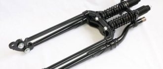
IL as a donor of spare parts
Let's consider, for example, the transition from 6 volts to 12 volts electrical equipment, and we will borrow the parts for such a conversion from the IZh motorcycle - fortunately, there are quite a lot of them sold in the post-Soviet space.
The wiring to Java will remain the same - if its condition is satisfactory, but the lamps and coil will have to be replaced. But you will get a more powerful system, which will affect all the characteristics of the motorcycle.
Scheme with decoding
Reasons for alteration:
- Elimination of weak headlight light is a phenomenon common to all Javas with 6V equipment;
- Elimination of undercharging of the battery during prolonged driving at low speeds;
- Breakdowns and failures due to wear of original 6V parts;
- Inability to purchase original components and consumables;
What do we take from the domestic motorcycle industry?
You will have to “implant” domestic parts into the Java scheme.
In fact, we will need a minimum set of parts from IZH:
- relay-regulator, indicated in the photo below under No. 1;
- generator rotor (under No. 2);
- stator windings (under No. 3);
- supply wire to the ignition switch at terminal 54 (under No. 4).