Constantly working to improve its models, in 1971 the Izhevsk Motorcycle Plant released a new motorcycle - IZH Jupiter 3, which had some differences from its predecessor.
In particular, the wiring diagram of IZ Jupiter 3 was modified, but the improvements turned out to be “capricious” and became the object of experimentation.
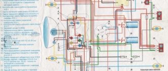
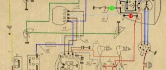
Original wiring diagram for IZH Jupiter 3, issued upon purchase of the motorcycle
Changes made by owners
The unreliability of individual components and faulty wiring on IZ Jupiter 3 forced the owners to delve into all the intricacies of the modernized elements.
And the first to cause numerous complaints were changes in the primary circuit of power supplies:
- Battery;
- Generator.
As well as ignition systems and circuits for lighting devices of the trailer module - a cargo-passenger stroller. In most cases, the reason for the refusal was a banal manufacturing defect.
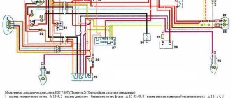
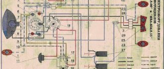
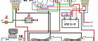
Redesigned color wiring diagram for IZ Jupiter 3
Battery charging system
Given the total shortage of spare parts for motorcycles that existed in those years, unplanned failure:
- battery;
- voltage regulator relay;
- ignition coils;
left the owners without transport for a long time. In addition, poor-quality assembly of individual elements led to unstable operation of all systems. This forced me to improve and polish the factory defects with my own hands (for example, see how to modernize the wiring diagram of IZH Planet 5).
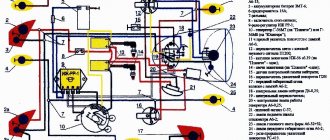
Wiring IZ Jupiter 3: structure of a modified relay regulator
Tip: the regulator circuit presented above has been tested on many motorcycles of the IZh family. Its peculiarity lies in the separate power supply - when turned on, the ignition circuit receives “+” from the battery. And the excitation windings are powered from the generator (terminal “I”) and do not discharge the battery when the engine is stopped.
Generator replacement
The operation of the standard G36M7 DC generator also caused a lot of comments. Frequent breakdowns and unstable operation forced the owners to look for a replacement.
The new modifications of the IZh family with 12-volt generators that appeared immediately attracted the attention of the owners of the IZH Jupiter 3, who were able to find a way to convert their motorcycle to a new operating scheme (see also the IZH Jupiter 5 wiring diagram).
The standard generator IZ Jupiter 3 could not cope with its duties
And among those that were freely available was the generator 281.3701, suitable for all series of “Planets” and “Jupiters”.
To re-equip the work it was required:
- Working generator 12 V;
- Block BPV 14-10;
- New 12-volt battery 6MTS-9, or another battery ZMT-8 (standard);
- New 12-volt light bulbs (to replace standard ones with 6V ones);
- Steel adapter plate for mounting a new generator;
- Right engine cover from IZH Planet 5 or Jupiter 5 models.
Photo of the blank for the adapter
Advice: DIY alteration of the cover for a new generator can result in damage. Therefore, experienced owners recommend purchasing an original cover from “older” models, which was originally designed for its mounting dimensions.
The instructions for installing a new generator are very simple:
- The adapter is installed in the right half of the crankcase;
- Fixed with short bolts with a diameter of 6 mm;
- The stator of the new generator is connected to the adapter through M5 threaded holes using three screws.
This is what the crankcase with adapter looks like
Ignition system
The ignition chopper is used to ignite a spark at a certain point in the piston stroke. In early modifications of the electrical wiring of Izh Planet 5, contact was mounted, later electronic.
The main malfunctions of this unit:
- Burning of breaker contacts is determined visually.
- Failure of a sensor or switch elements - the easiest way to detect it is to use the method of installing a known-good unit. The lubrication system sensor valve is also checked using the same method.
- An incorrectly set ignition timing is visible from the fuzzy operation of the engine. It can be eliminated by adjustment using special probes.
The ignition coil increases the voltage to several kilovolts so that the discharge can ignite a spark at the spark plug electrodes. The secondary winding is made of a fairly thin wire; most often it burns out. Although a breakdown between the turns or onto the housing is also possible. The same troubles can (but less often) happen to the primary circuit. Everything is revealed using resistance measurements.
Motorcycle Upgrades
New electrical devices have appeared on the motorcycle:
- New generation alternating current generator with a power of 100 W;
- A new electronic unit consisting of a rectifier and voltage regulator BPV14-10;
- Electronic switch;
- Ignition coil IZH-PS;
- Modern instruments and warning lamps.
In addition, the power of lighting devices has increased, in comparison, for example, with:
- Headlights;
- Side lights;
- Direction indicators;
- Stop lights.
For reference: the combination of engine reliability and improved visibility has increased vehicle safety on public roads.
conclusions
We hope that the electrical diagrams and video material presented in the article will help you in the maintenance and technical care of the IZH Jupiter 4 motorcycle. And thanks to your care, it will serve without fail for many more decades.
Constantly working to improve its models, in 1971 the Izhevsk Motorcycle Plant released a new motorcycle - IZH Jupiter 3, which had some differences from its predecessor.
In particular, the wiring diagram of IZ Jupiter 3 was modified, but the improvements turned out to be “capricious” and became the object of experimentation.
Differences from the second Planet
For many modern citizens, the information that domestic motorcycle manufacturers worked tirelessly to improve their models in an era of total shortages may come as a surprise.
Note! The fact takes place, moreover, it is supported by official documents, in particular 1970N04P16-17 - this is the outgoing number of the factory newsletter, which described the changes made.
In the photo - official materials of the Izhmash Design Bureau
The new generation motorcycle received:
- Direction indicator lights are a first in domestic practice;
- Semiconductor relay for controlling direction indicators (installed in the headlight);
- New size of wheels and tires (3.50x18 versus previous - 3.25x19);
- New brand increased capacity battery (old one on IZH Planet 2 - ZMT-6);
- And, of course, more engine power. The power unit now developed 18 hp.
Modifications
But the creator engineers did not stop there and, having released the five-millionth car from the production line, presented a modification of the IZH Planet 3-01.
Mirror and safety arches are the distinctive features of the new modification
Among the innovations it should be noted:
- Rear passenger footrests;
- Roll bars;
- Rearview mirror;
- New steering wheel design.
For reference: The buyer paid for the changes out of his own pocket. In particular, the price for IZH Planet 3-01 was 750 rubles, the version with a stroller was 1140, and the “rural version” was even more expensive. Fortunately, care instructions were included with purchase, which made maintenance easier.
Contactless ignition system
The wiring diagram of IZ Jupiter 4 had one more difference from motorcycles of previous years of production, for example from.
It was equipped with a non-contact electronic ignition, which improved all performance characteristics:
- Engine power increased by 3 hp;
- It is now possible to operate a motorcycle even with a dead battery.
Setting the ignition timing
Unlike the classical contact ignition scheme, where the contact opening time can be determined and adjusted using a signal light, such methods are not applicable in a contactless ignition system (BCI).
Caution: The IZ Jupiter 4 wiring is not intended for testing the high-voltage wire for a spark - only on a spark plug leaning against ground. The fact is that too large a distance of the wire from the ground will provoke a voltage surge in the secondary winding of the coil, and the discharge will disable it. As a rule, such an “experiment” also disables the output transistor of the switch, which automatically leads to its failure.
To set the ignition timing it is necessary:
- Connect a voltmeter with your own hands to the circuit with the Hall sensor. Connect the “+” wire to contact No. 2, and connect the “-” wire to No. 3;
- turn the crankshaft to the position corresponding to the moment of spark formation in one of the cylinders;
- turn on the ignition;
- turn the modulator until the voltmeter readings change;
- the voltage surge corresponds to the moment of discharge of the BSG;
- fix the position of the modulator using the fastening bolt;
- repeat the operation for the second cylinder.
Tip: Use a voltmeter with a resistance of 10-50 kOhm, equipped with a scale of at least 15 V. This voltmeter will allow you to read the readings more accurately.
Electronic switch
A special feature of the contactless ignition system is an electronic switch. In fact, on all motorcycles and cars without exception, equipped with a three-phase asynchronous generator with electromagnetic excitation, it is absolutely the same.
Therefore, installing VAZ switches on motorcycles is not a whim or “stupidity”, but a completely reasonable approach from an electrical point of view:
- their operating principle is the same;
- operating parameters are similar;
- Overall dimensions allow installation on a motorcycle in a tool box.
For reference: on top of that, the price of “foreign” switches is cheaper due to their mass availability. Whereas on IZh Planet and Jupiter switches are a rather scarce spare part.
Voltage regulator
Another feature distinguishes IZ Jupiter 4 is the BPV14-10 rectifier and voltage regulator unit:
- It measures the voltage in the network;
- When it falls (low generator speed), the relay increases the supply of bias current;
- When increasing (high generator speed), the relay reduces the bias.
As a result of such work, the voltage in the on-board network of the motorcycle is constantly kept at the level of 14-14.5 V. This was done specifically so that the battery does not participate in the sparking process and is constantly charged.
How to check the charging of the Izh Jupiter generator
First you need to check whether the generator windings are shorted to ground. To do this, take a 12 volt lamp, solder 2 wires (probe) to it, turn off the BPV, turn on the ignition, connect one wire of the lamp to the wire that connects to terminal X8 (BPV), this will be the “+” of the battery (AK). We connect the second wire one by one to wires X5, X4, X7, X1 - the lamp should NOT light up. If the lamp lights up, even not at full strength, it means that the windings are shorted to ground - these could be the wires that go to the generator or a short in the generator itself. X5, X4, X7 - stator windings, X1 - excitation winding.
(if the excitation winding is short to ground, quite unpleasant consequences are possible! such as melting of the brushes, blown AK fuse, if you have one of course :), if not, then the wiring will burn.)
We check the serviceability of the generator operation indicator lamp. To do this, we short-circuit X8, X3 (BPV is turned off, the ignition is on), the control lamp should light up, if not, check the lamp and the wires suitable to it. Now we check the excitation winding, for this we connect one wire of our probe to ground, and the second to X1 (the BPV is turned off, the ignition is on), the probe should light up, if it does not light up, the excitation winding is faulty. (this could be a stuck brush, a break in the wire leading to the brush, or a break in the field winding).br/> If all our tests give a positive result, we check the operation of the generator. To do this, we close wires X1-X2 (the BPV is off), turn on the ignition, start the motorcycle, connect the probe with one wire to ground, and alternately connect the second wire to wires X5, X4, X7, the probe should light up. If the lamp does not light on any wire, it means that the stator winding or the wire suitable for it is faulty. If everything is OK, then the generator is working.
Switching elements.
These include switches (high-low, turns, engine stop, etc.) as well as brake and neutral sensors and the ignition switch. You can easily “ring” them with a tester, finding out which contact group is not working.
Switching also includes the Izh electronic turn signal relay. Its malfunction is visible by the absence of interruption or no voltage supply to the turn signals.
As can be seen from all of the above, the wiring on Izh Planet is without any special secrets or complex elements, all its parts are easily diagnosed and repairs should not cause difficulties.
Now we advise you to watch the video, which shows in detail and clearly the assembly of the Izh Planet 5 circuit.
The IZ Jupiter 4 wiring diagram has become a revolutionary solution for all domestic motorcycles. It was with this model that the Izhevsk Motor Plant began to equip motorcycles with 12-volt equipment, which significantly increased spark generation in the ignition system.
Model features
Therefore, even today, enthusiasts retrieve famous motorcycles from dusty sheds and garages, restore them to their original form and, as before, give the spirit of freedom to their owners.
What is especially pleasing is the interest of modern youth in domestic technology. This article is intended for them and their parents who had the opportunity to ride Izhaks, Jupiters and Planets.
Electrical diagram
The IZH Jupiter 3 model appeared as an improved example of the previously produced IZH Jupiter 2. For the first time in domestic practice, a motorcycle received turn signals, and therefore the wiring diagram of the IZH Jupiter 3 has undergone changes.
In particular:
- There was a separate cable running under the gas tank and seat to the rear turn signals;
- For the model with a side trailer, a second cable was laid and attached to the stroller frame.
The new model is based on the proven electrical circuit of its predecessor.
The photo above also shows the wiring for the IZ Jupiter 3 in the version with a sidecar.
They asked from her:
- Lamp (yellow) for trailer brake lights (indicated as 2a in the diagram);
- Lamp (red) for the rear marker light of a trailer (3a);
- Right direction indicator on the trailer fender (11);
- Trailer front marker light (white) (17).
One can argue for a long time about the quality of products of the domestic motorcycle industry, but a motorcycle in capable hands required only preventive maintenance and adjustment. And the era of shortages forced owners to show miracles of ingenuity, modifying unreliable components and assemblies of their two-wheeled horses.
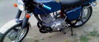
For reference: Izh Jupiter 3 deservedly received the Quality Mark. This was evidenced by a sign on the frame - in the photo below. Today, finding such a motorcycle without “crooked” improvements is a great success for collectors.
Self-improvement
Many were not satisfied with the capricious ignition of the motorcycle (see article), so the wiring diagram on the IZ Jupiter 3 was often altered from 6 to 12 volt. This was facilitated by the appearance of the 281.3701 generator produced by the Izhevsk Motor Plant, which was much better and more reliable than the standard G36M7. Those owners who were not able to get it had to upgrade the existing one.
For this:
- A steel adapter plate was machined, allowing 12 internals to be installed in the generator;
- The right engine cover was purchased or exchanged from older models Jupiter 5 or Planet 5.