Thanks to the electronic device, adjusting the unit will not take much time and effort.
In this case, do not unscrew or remove the modulator, otherwise you will have to install everything again! Set the ignition separately for each cylinder.
After this, the screws must be tightened tightly. How to Connect Chinese Wiring Izh Planet Izh Jupiter Then loosen the screw and turn the eccentric. For reference: unlike the Jupiter model, new wiring and an electronic ignition system were installed on the modified IZ Planet 5. If it was not possible to cause a spark using the steps described above, then the reason for the incorrect operation is incorrect connections.
Keep in mind that you will also have to adjust the outline at the same time. Do not try to fix the wire with your hands - it will jump so hard that sparks will fly out of your eyes.
Burnt contacts, oily spark plugs and batteries with a charge of less than 12 V further worsen sparking. It is very important that the modulator plate passes through the slots of the sensor itself.
It should fit into the hole made in the sensor. In the diagram above, the numbers indicate: Spark plugs;.
We do wiring on IZ Jupiter 5
Specifications[ | ]
- Overall length 2,115 mm.
- Overall width 780 mm.
- Overall height 1,025 mm.
- Ground clearance 135 mm.
- Dry weight of the motorcycle is 160 kg.
- Maximum speed 110 km/h.
- Fuel tank capacity 18 l.
- Cruising range on the highway is 400-450 km.
- Fuel consumption on the highway is no more than 4 liters per 100 km.
- Fuel: Gasoline with autol 10-18 in a ratio of 25: 1
- Fordability 300 mm.
- Engine Stroke 58 mm
- Cylinder diameter 61.75 mm
- Number of cylinders 2
- Engine displacement 347 cm3
- Compression ratio 6.8
- Maximum power 18 hp. With.
- Air cooling
- Lubrication system combined with fuel
- Carburetor type K-28ZH
Multi-disc clutch, in an oil bath with an automatic release mechanism. The gearbox is four-speed, two-way. Motor transmission is a rollerless double-row chain, gear ratio - 2.57. Transmission from the gearbox to the rear wheel is a roller chain, gear ratio - 2.33. The frame is tubular and welded. The front fork is a telescopic spring type with hydraulic shock absorbers. Rear suspension pendulum spring with hydraulic shock absorbers Type of brakes drum Type of wheels easily removable, with tangential straight spokes. Tire size 3.25-19″
Maintenance Features
Often during operation it is necessary to correctly set the gap between the contacts of the breaker. To do this, you need tools and a diagram to see which elements need to be dismantled.
Wiring diagram for IZH Planet 5: connecting instruments and controls
The algorithm of actions is as follows:
- place the motorcycle on the stand;
- turn on neutral;
- unscrew the spark plug from the cylinder;
- remove the engine crankcase cover;
Breaker adjustment process
- turn the crankshaft until the contacts are as open as possible;
- using a screwdriver, loosen the locking screw;
- using a special feeler gauge, set the gap to 0.35-0.45 mm and fix it with a screw;
- we collect everything in reverse sequence;
The process of measuring the gap using a feeler gauge
- turn on the ignition and start the engine. Its stable operation at idle indicates that the adjustment has been correctly performed.
In general, all the wiring of IZH Planet 5 is very easy to do with your own hands.
The need for such work often arises when operating a motorcycle:
- in wet weather, driving in the rain for a long time (oxidation or dampness of electrical contacts);
- when traveling over rough terrain, replete with vegetation and bushes (mechanical damage to wiring);
- when used in winter (snow and slush stick to the wires and can damage them).
Often the sound signal suffers during operation. Its malfunctions manifest themselves in the form of deterioration in sound quality.
To restore its functionality, you must perform the following procedure:
- loosen the locknut using an open-end wrench;
- turn on the ignition;
- press the button to turn on the sound signal;
- use a screwdriver to adjust the tone;
- repeat the procedure until we get a clear and loud sound;
- tighten the control nut.
Motorcycle Horn Adjustment Screw
Conclusions: we are confident that this article will help you in servicing motorcycles of the IZH family (see also the article on the IZ Jupiter 5 wiring diagram). Both the attached diagrams and description will help you avoid making mistakes during operation.
10/19/201916Wiring and electrical circuits
Battery
The battery in the motorcycle is low-power. The motorcycle does not have a starter, so its task is only to supply voltage to the ignition system and the generator excitation winding during starting. Thanks to the battery, designed for 12 volts, a stable start of the fifth Planet is ensured; up to the third model, the wiring was 6 volt, and the ignition was not always clear.
Possible battery malfunctions:
- Mechanical damage - housing, plates, leakage of electrolyte.
- Loss of electrolyte density is determined by measurements using a hydrometer.
- The short circuit of the plates in the banks is detected by measuring the resistance.
- It is possible that the connection is not correct, minus not on the body (frame) of the motorcycle - all the electronics will not work.
Setting the appropriate options
Setting up the BSZ on Izh Jupiter 5 also requires special attention. The ignition is turned on with the tachometer connected. After thirty seconds, indicators of 3000, 4000, 5000 rpm should appear on the device panel. If they are present, then the switch is working correctly.
In other cases, you should pay attention to previously grounded candles. We insert a screwdriver into the hall connector, and then pull it out
A spark should appear on the spark plugs. If it was not possible to cause a spark using the steps described above, then the reason for the incorrect operation is incorrect connections.
The setup looks like this. The dial indicator is unscrewed and the cylinder piston is adjusted. Having connected the voltmeter to the second and third connectors, you need to start rotating the modulator axis. After a jump from 7 to 0.1 volts is detected, the modulator must be secured with a nut. Usually the required advance angle is set.
The test run should be successful if you install the components yourself according to the instructions. Now you can use BSZ.
The main problem with the Izh Jupiter motorcycle engine is the standard contact ignition system. Any owner of Jupiter sooner or later faces the problem of failure of one of the cylinders due to a change in the gap in the contacts or failure of the capacitor. Adjustment helps, but usually not for long. This problem can be radically solved by installing a contactless ignition system on a motorcycle.
Single-channel BSZ.
There are probably many options for BSZ design, but we won’t consider them all. Let's focus on the simplest, and probably the most common option in our country. There is no motorcycle market or motorcycle store nearby where you can buy a factory-made BSZ, and there is no turner with a machine nearby either. We will proceed from this.
Minimum set for installation
But we can’t do without a minimum set, so before you start work, you need to stock up on the following components, which are sold in any auto shop or car market in our country:
1. Switch from VAZ 2108
2. Hall sensor from VAZ 2108
3. Set of wires for BSZ from VAZ 2107 (from distributor (Hall sensor) to switch)
4. Two-terminal ignition coil (from an Oka or Gazelle car with a ZMZ 406 engine)
5. Two automotive silicone high-voltage wires of the required length with caps for spark plugs (you can buy a kit for a VAZ and take it from there, you can simply find used wires, after first making sure they are working)
Next, in addition to the components, we will need a small flat piece of sheet steel 1-1.2 mm thick to make a modulator and a plate for the Hall sensor. I warn you right away that stainless steel or non-ferrous metals are not suitable for the manufacture of the modulator, since they are not magnetic materials. To make a plate for the Hall sensor, you can use any material of sufficient strength.
Tools you may need are a drill with drills, files, a chisel, a hammer and other tools that, as a rule, are found in any garage.
Rework process
We dismantle the old ignition system. We remove the plate with contacts, capacitors, ignition coils with high-voltage wires from the motorcycle. We install the switch in the right glove compartment.
We attach the ignition coil to the frame under the tank. We connect the wiring connector to the switch, connect the black ground wire from the connector to ground. We connect the wire from terminal No. 1 of the switch connector to one of the coil terminals. We connect the second terminal of the coil to the old wiring, to the wire to which “+12V” is supplied when the ignition is turned on. In the old wiring, this wire connected both ignition coils. From it we pull an additional “+12V” wire to the switch, which we connect to the 4th wire in the connector. We carefully isolate everything. We insert the wire with the connector to the Hall sensor into the cavity of the generator.
You can check the functionality of the system. We connect the Hall sensor to its connector, connect the high-voltage wires to the coil and to the spark plugs. We provide reliable weight to the candles. Turn on the ignition and pass a metal object (you can use a flat screwdriver) through the Hall sensor slot. The spark plugs should spark. The scheme is working. (If there is no spark, then something is connected incorrectly and everything needs to be checked again.) Now it remains to supply a spark at the right time to the cylinders, for this:
Golden rules for tuning the ignition on Jupiter: cheat sheet for IZhovodov
In what cases is ignition adjustment necessary?
During the operation of the vehicle, the owner faces many problems. The most serious failure is related to the engine. In order to spend significant funds on major repairs, it is necessary to monitor the technical condition of the motorcycle and carry out preventive work, including adjusting the valves and valves (video author - Hana Rulyu).
If you do not monitor the SZ, then the motorcycle engine may not reveal its full potential and will not work at full capacity. This can lead to a reduction in its service life. An ignition adjustment is necessary if the engine is running poorly, the muffler or carburetor is firing. True, before setting up the SZ, you should make sure that the cause of the malfunction is in it.
It happens that the flywheel bolt, which connects the two halves of the crankshaft, comes loose, begins to play and does not work well. Sometimes he even cuts the key.
Setting up the SZ may be necessary after repairing the ignition switch Izh Jupiter 5. The installation and connection itself are carried out according to the diagram.
SZ diagram of the IZh motorcycle
Step-by-step guide to installing and adjusting the ignition
To carry out the setup, you need to prepare a special tool, a tester, and a light bulb with two wires. A caliper will be needed as a depth gauge. To set the gap it is convenient to use a special feeler gauge.
Setting up SZ on IZ Jupiter 5 consists of the following steps:
- First open the generator cover.
- To make it more convenient to work, remove the right cover from the crankcase.
- Using the generator bolt, turn the crankshaft clockwise. It is necessary to ensure that the breaker contacts open to the maximum distance.
- Unscrew the screw a little and turn the eccentric. It is necessary to set a gap between the contacts equal to 0.4-0.6 mm. After this, tighten the screw well.
- Rotate the crankshaft in the direction of movement of the clock hand. The piston should be installed at TDC.
- You need to turn the crankshaft in the opposite direction, that is, counterclockwise. In this case, the piston should not reach TDC; a distance of approximately 3.0-3.5 mm should remain. By loosening the screws, you should establish the beginning of the contact closure. After this, the screws must be tightened tightly.
- To determine if the contacts are open, use a test light with wires. One wire must be connected to the breaker hammer terminal, and the other to ground. After turning on the ignition, when the contacts are closed, the light should light up.
- If BSZ is installed on IZ Jupiter, then there is no need to set the gap. To determine the moment you need to use a tester. The device should be set to measure voltage. The probes must be connected to the 2nd and 3rd contacts of the DC. While the modulator is not in the DC, the voltage reading on the tester should be 7 V. At the moment when the modulator is in the DC, the voltage reading should be in the range from 7 to 0 V. At this moment, a spark is formed.
- The procedure must be performed on each cylinder. It is advisable to start adjusting the gap on the left breaker. When the left breaker is configured, you can move on to the right one.
SZ motorcycle IZH
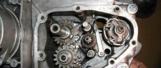
Engine diagnostics and repair
It is sometimes impossible to find the cause of a breakdown after one visual inspection. In some cases, complete disassembly of the IZH Jupiter 5 engine is necessary. But if you find out the reason, you can quickly solve the problem yourself. Here are examples of main faults and repair recommendations:
- If your kickstarter turns on the crankshaft, you must:
- Tighten the fasteners more tightly, and in case of severe damage, replace the kickstarter shaft and lever. This usually happens after the IZ Jupiter 5 engine has been boosted.
- If the oil is selected incorrectly, especially if it is very viscous in winter, it is necessary to select a more correct temperature regime.
- If the trigger spring is weakened, it must be replaced.
- If no fuel gets into the carburetor, you should clean it in a solvent, and also blow out the channels and fuel supply hose with pressurized air.
- If there is no spark in the combustion chamber, replace the spark plug or clean it.
- When the throttle valve sticks, it is necessary to adjust its drive and clean the carburetor.
If the engine is unstable or does not start the first time, it is worth checking:
- Fuel supply system. The fuel mixture may be oversaturated with air. The solution to this problem is to replace the air filters and install new gaskets.
- Is the capacitor OK? If strong sparking occurs between the contacts, the capacitor must be replaced.
- Severe wear or burning of the spark plug. In most cases, it is the spark plugs that cause poor starting and uneven engine operation.
In cases where the motor stalls after a short period of operation:
- The drainage hole of the fuel drum should be cleaned.
- There are cases where the carburetor needle falls out. It needs to be inserted into place and adjusted.
During unstable operation under load, the following occurs:
- Cleaning and purging of carburetor channels and jets.
- Adjusting the carburetor to supply gasoline for a combustible mixture. When the quantity is large, popping noises occur in the muffler, because the mixture hits the hot metal walls and burns out there.
- If the fuel manifold drive becomes stuck, the needle must be returned to its standard position.
- In case of low cylinder compression, it is necessary to remove all carbon deposits from the piston and clean the piston rings. And in case of severe damage, completely replace the piston along with the cylinder. To prevent malfunctions, you should use only high-quality fuel and oil from trusted manufacturers.
- Ignition adjustment. With early ignition, you can hear the engine knocking, and with late ignition, popping noises in the exhaust pipe.
Engine overheating and loss of power occur for the following reasons: Driving in the heat at low gearbox levels during a long trip. It is worth stopping periodically and letting the engine cool. Insufficient amount of oil in the fuel mixture. Heavy carbon deposits on the cylinder and piston walls. As mentioned earlier, for prevention it is worth cleaning the engine as often as possible.
These are the main problems that may occur during operation. How to disassemble the IZ Jupiter 5 engine is written in detail in the maintenance book issued upon purchase. Everything stated in it is written in clear text, with diagrams and detailed instructions. Not only the repair of a Soviet unit is within the power of any owner.
There are many questions about how to assemble the IZH Jupiter 5 engine yourself, modifying it. For example, installing a more reliable carburetor or a more stylish and loud muffler can be done quickly enough without significant financial investments.
Tuning an IZH Jupiter engine with your own hands is possible if you have enough time and enthusiasm. You just need to be persistent.
The motorcycle has a favorable ratio of cost, build quality and maintenance requirements. An ideal option for people with a small budget and those who want to get universal equipment. However, frequent breakdowns will take a lot of time. It's worth being prepared for this, since some bikes can be 40-50 years old.
Maintenance
The owner can independently perform some maintenance procedures:
- check the motorcycle generator if the battery loses charge;
- set the gap between the breaker contacts;
- adjust the quality of the sound signal.
The need to inspect and adjust the wiring arises if:
- the motorcycle moves in the rain for a long time, as this causes oxidation of the contacts;
- a motorcyclist rides in an area with a lot of vegetation that damages wiring;
- The driver rides in snow in winter, which can stick to electrical wiring parts and damage them.
Self-check of the Planet 5 motorcycle generator in case of loss of charge
The cause of loss of charge in the IZH Planet 5 battery is most often a breakdown of the generator.
To check it yourself you need:
- multimeter device;
- straight screwdriver.
Step-by-step instruction
The following steps must be followed:
- Disconnect the wires from the battery and remove the generator cover.
- Disconnect the top 5 wires from the generator, first unscrewing their fastenings. In order not to mix up the wires during assembly, it is worth marking them.
- Measure the winding resistance using a multimeter in ohmmeter mode. To do this, you need to touch the body with one probe, and the other should be connected in turn to the 3 wires of the winding. There should be no short circuits, as indicated by the inscription on the multimeter screen.
- Test the resistance between the stator contacts: you need to touch them one by one with the multimeter probes. The value on the screen should be 8 ohms.
The presence of a short circuit in the 3rd stage or a discrepancy in the indicators in the 4th will indicate problems with the generator.
Photo gallery: stages of checking the IZH Planet 5 generator in case of loss of charge in pictures
How to correctly set the gap between the contacts of the breaker?
In order to set the gap between the breaker contacts, you will need:
- straight screwdriver;
- wrench 10;
- candle key;
- probe 0.4 mm thick (+/– 0.05 mm).
Next, you need to follow the steps sequentially:
- Place the motorcycle on a stand and place the gearbox in neutral.
- Remove the right crankcase cover and unscrew the spark plug.
- Using a 10mm wrench, grab the generator rotor mounting bolt and turn the crankshaft to a position where the contacts are as far apart as possible.
- Loosen the screw securing the contact.
- Place the probe between the contacts and adjust the tightening of the eccentric screw until the probe passes the contacts with little resistance.
- Tighten the contact fixing screw.
Photo gallery: adjusting the gap between the breaker contacts
Troubleshooting the audio signal and improving signal quality
Poor sound signal quality is mainly caused by improper adjustment.
The following tools will be needed for setup:
- wrench 7;
- a simple screwdriver.
Step-by-step instruction
To adjust, do the following:
- Loosen the locknut with a wrench.
- Turn on the ignition.
- Press the button to turn on the sound signal.
- Adjust the sound by rotating the adjusting screw.
- When the desired result is achieved, tighten the locknut.
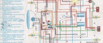
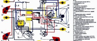
Electrical circuits of the ignition systems of the IZH Jupiter 5 motorcycle
1 - parking light lamp - A 12-4; 2 - high beam - low beam headlight - A 12-45:40; 3 - indicator lamp for generator operation - A 12-1; 4, 5 — speedometer scale illumination lamps — AMN 12-3; 6, 16, 17, 20, 23, 30 — lamps for the direction indicators of the motorcycle and side trailer; 7 - combination switch (right switch); 8 — brake light switch for the front wheel brake; 9 - breaker; 10 — spark plug; 11 — ignition coil; 12 - generator; 13 — rectifier-voltage regulator BPV14-10; 14 — brake light switch for the wheel brake; 15, 19 — side trailer clearance lamps — A 12-5; 18 — brake light lamp for side trailer — A 12-21-3; 21 — motorcycle brake light lamp — A 12-21-3; 22 — motorcycle rear marker lamp — A 12-5; 24 - battery; 25 - fuse; 26 — neutral lamp switch; 27 — ignition switch; 28 — sound signal; 29 — alarm switch (left switch); 31 — turn signal switch; 32 - high beam headlight control lamp - A 12-1; 32 — control lamp “neutral” — A 12-1; 33 - control lamp for direction indicator lights - AMN 12-3; Symbols on the BPV14-10 block (items 12,13): XI - “-” excitation windings; X2 - “-” battery (“ground”); ХЗ - “+” output to the control lamp; X4, X5, X7 - phases of the stator winding of the generator; X8 - “+” of the battery.
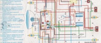
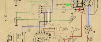
Wiring diagram IZH Planet 5
Detailed color wiring diagram for motorcycle IZH Planet 5
Explanations for the diagram
The numbers on the electrical diagram correspond to the following elements:
- Light switch, dimensions/low.
- Light switch, direction indicators and horn buttons.
- Front turn signals.
- Instrument panel lighting.
- Indicator lamp for generator operation.
- Oil pump operation indicator.
- A light indicating the operation of the neutral gear in the gearbox.
- Direction indicators.
- High beam headlight indicator.
- Front parking light bulb.
- Headlight lamp.
- Sound signal.
- Hall Sensor.
- Generator.
- Egnition lock.
- Turn signal interrupter relay.
- Neutral gear warning lamp sensor.
- Block BPV 14-10.
- Switch.
- Battery.
- Fuse.
- Relay block.
- Ignition coil.
- Foot brake light sensor.
- Rear direction indicators.
- Rear light with lamps.
Description of the symbols for the terminals on the rectifier-regulator block BPV 14-10:
- –x1 — “minus” of the generator excitation winding;
- –x2 — “minus” of the battery (“ground”);
- x2 - “positive” wire to the control lamp of the instrument panel;
- x3 - “positive” wire to the panel indicator;
- x4, x5, x7 - phases of the stator winding;
- x8 - “plus” of the battery.
Video “Installing BSZ on IZ Jupiter 5”
This video talks about installing a contactless ignition system on a Jupiter 5 motorcycle (the author of the video is Andrey).
I have in my garage my “Old Friend” IZH Yu-5, which was given to me when I graduated from school! The only owner of which is only me. I haven’t driven it for a long time, more than 10 years, and it wouldn’t start, there was no charging, constant problems with the cams and dead ignition coils, and of course the right pot! It's time to resuscitate my friend! It was decided to install the BSZ, do normal charging with car elements and replace the wiring! I go to the store and buy parts:
1. Relay – regulator 2101, 2106.2. Generator diode bridge (suitable for VAZ and GAZ generators. 3. Capacitor for diode bridges (in my opinion, they are all the same for VAZ and GAZ) 4. 2 spark plugs from GAZ with an electronic ignition system. 5. 2 short high-voltage silicone wires (I bought them for fifty dollars in some garage cop)6. Ignition coil (VAZ 1111, GAZ with engine 406) two-terminal, dry.7. Switch (VAZ 2108)8. Hall sensor (VAZ 2108)9. Connecting blocks for the switch and Hall sensor.10 . Emergency ignition. (just in case) 11. Terminals, wires, electrical tape and nut - I think everyone has them in the garage 12. I ordered a modulator plate and a hall sensor mounting plate on the Internet, so I could sharpen it myself into scrap))
Installing the BSZ1. Remove the breaker contacts, coil, capacitor and all the other crap from contact ignition. 2. Put the switch in the right glove compartment, the coil under the tank. 3. Unscrew the generator bolt. 4. Install the modulator. 5. Attach the Hall sensor. 5.1. We fasten the modulator, but do not tighten it! 6. Connect everything according to the following diagram. Save to Album Scheme 1 Scheme 1
7. We put the armor wire on the candle, connect it to the coil. Everything is done according to the first scheme, everything is done in an elementary way and in time you can manage it in an hour with smoke breaks.8. Connect the ignition coil. Save to Album Diagram 2 color Diagram 2 color
The ignition is set simply: the piston is at TDC further 3.5 mm back and for the convenience of finding the moment of the spark, an instant diagnostic unit “MD-1” was purchased
Next we start charging1. We throw out all the elements of the old charging system2. Brushes. Since the relay-regulator used controls the current on the rotor through (+), you need to do the following. Plastic blocks are installed on the generator housing, which allow you to isolate the wire connections from the housing. We find the connection between the white brush wire and the short wire with the black wire and release the brush wire (unscrew the nut on M3). There is a 3mm terminal mounted on it, we drill it out to 4mm. And now we put this terminal on the mounting screws of the block itself and tighten it, thereby feeding it to the brush (-). 3. Diode bridge. On the BPV, black wires (-) go to the lower left part of the BPV and red wires (+) to the middle lower part of the BPV. And three pink ones on the right side of the GSV. We release the black ones and twist them, and we do the same with the red ones. And we remove the pink ones (they come from the generator from each phase and supply alternating current from each phase, of which there are only three) and leave them as is. The diode bridge consists of two plates, one of them is (+), the other (-) and they are insulated from each other, the plate that has insulation on the mounting hole (at the end) is (+). We connect the red wires (+) to plate. And we connect the black and brown ones to ground (-). The diode bridge is connected. 4. Relay regulator. Take (+) anywhere after the ignition key. This terminal will go to the groove size No. 15. We take the wire (+) of the brush, it was removed from the lower right part of the BPV, this is the wire for terminal size No. 67. We take the solution and connect it. Next, we screw the solution to ground; you can’t start it without this, otherwise it will burn out! 5. To make sure the charging light on the dash goes out, put it through the relay.
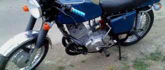
The main visual difference between the two motorcycles of the IZh family is the number of engine cylinders. The Jupiter 5 model has two of them, while the Planet 5 has only one.
In all other respects, the models are maximally unified with each other, with the exception of electrical components.
System assembly and installation
The contacts in the breaker, the capacitor, the ignition bobbins and the armor wires, which are part of the previous ignition device, are probably eliminated. The switch should be installed in the glove compartment on the right, and the ignition coil directly under the tank. There are no gaps for fastening on the reel, which means it can be attached using a thick layer of adhesive tape. The standard bolt is also eliminated along with other parts.
In place of the bolt, install a pin of the specified size and put on a washer. Then, the rotor is tightened with a nut located at its end. The hall sensor is attached to the stator by any means. The basic rule when installing it is to set the optimal cross-sectional distance of the modulator and the ratio of the radius and line of symmetry.
When the hall sensor can be secured, we apply the modulator. It should fit into the hole made in the sensor. In most situations, there is a discrepancy between the sizes, so it is necessary to place washers on the stud. If you manage to maintain the required gap, it is recommended to install an engraver and tighten the modulator with a third-party nut.
Improving the standard system
The ignition system can be improved in other ways. To do this, you need to identify what problems there are with the wiring. They can occur in the primary circuit between the coil and the 12V battery or due to operating conditions. A visual inspection of the primary circuit can reveal problems with connections, contacts and the ignition switch.
But when dirt and dust get into the circuit, the resistance at the contact points increases, which entails a decrease in voltage from 12 Volts to 7-8 Volts. This voltage is not enough for a powerful discharge to appear in the secondary winding of the coil. As a result, a charge of less than 12 V appears on the spark plug, which poorly ignites the combustible mixture in the cylinders. Burnt contacts, oily spark plugs and batteries with a charge of less than 12 V further worsen sparking.
Standard wiring after modification
The following measures help solve these problems:
- The plug connectors are removed and each wire is soldered using traditional soldering and then insulated.
- An additional toggle switch is installed that turns off all consumers when the engine starts. Thus, the coils are supplied with 12 volt voltage from the battery (diagram 1).
- Remake the ignition switch (IZ) (diagram 2). You need to take a wire and solder one end of it to the connector of lock 4, which is free, and the other to the positive terminal of the coil. The standard wire should be re-soldered from terminal 5 to terminal 6. After turning on this position of the key, power is supplied from the battery to the primary circuit according to a simplified scheme.
Loading …
Generator
The motorcycle is equipped with a 3-phase alternator, which has an electromagnetic excitation circuit. The principle of its operation is based on some features. So, the electrical circuit of IZH Planet-4 looks like this: the current is supplied to the rectifier, which, in turn, converts it into direct current, then supplies it to consumers through the ignition switch. The factory instructions for the generator contain the following elements:
— voltage regulator with rectifier “BPV-14-10”;
— generator stator together with windings;
— generator rotor;
— cam of the battery ignition system and contact unit of the ignition system;
- current collector brushes.
For reference: the windings on the three-phase generators of the IZH Planet-4 motorcycle are connected in a “star” or “delta” type, and the rectifier is installed as a separate unit, and the electrical wiring is directly connected to it.