While maintaining much of the continuity with previous models, the IZH Planet 4 motorcycle featured new design changes. And first of all, this is 12 volt equipment, which previously appeared on two-cylinder Jupiter models.
New items also include improved appearance, European lighting technology and a new ignition switch.
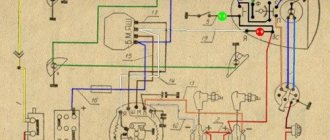
Original color wiring diagram for IZH Planet 4
Features of electrical equipment
The wiring diagram of IZH Planet 4 is almost completely copied from the Jupiter model that was the first to appear on the factory assembly line.
The only differences are that:
- The Planet family has one working cylinder, and accordingly the ignition system is designed to ensure its operation;
- The IZ Jupiter family, unlike the Planet, has 2 working cylinders; accordingly, the wiring diagram has additional repeating elements.
For reference: the possibility of operating a motorcycle with a trailed sidecar is also taken into account. The wiring diagram on IZH Planet 4 has a connector for connecting the right turn signal repeater and side lights.
Headlight
IZH Planet 4 is equipped with more advanced lighting devices:
- Headlight type "European beam" FG137V with glass with an asymmetrical pattern;
- Low beam mode with lamp A12-45 + 40 W;
- Modern direction indicators type 16.3726 (lamp power - 25 W).
Photo of IZH Planet 4 model 1986
Thanks to the modernization of the lighting system, as well as the configuration of the motorcycle:
- battery 6MTS-9;
- high power alternating current generator 100 W,
The illumination of the road in the flow of traffic has significantly improved, and traffic on public roads has become safer. At the same time, the price of the motorcycle did not change significantly, which brought its sales to a new level of popularity.
Contactless ignition system
The motorcycle used a new contactless ignition system, the operating principle of which was based on the following operating algorithm:
- The generator rotor generates pulses when rotating;
- The storage capacitor is charged through diodes (in the diagram below indicated as VI, V5), as well as through a limiting resistor (R1);
- Passing through the diode (V6), the electrical signal from the sensor winding (3) enters the thyristor (V4);
- After it opens, the charged capacitor (C1) transfers the accumulated charge to the ignition coil (primary winding - 4);
- Under its influence, a high voltage pulse is induced in the secondary winding;
- Through the high-voltage wire, the central electrode of the spark plug receives a charge;
- A spark between the electrodes ignites the air-fuel mixture in the motorcycle engine cylinder.
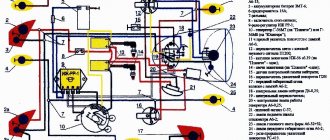
The factory instructions contain the original diagram of the contactless ignition system
The electrical wiring of the IZH Planet 4 motorcycle, due to the peculiarity of the contactless ignition system, has differences in the layout of the main components:
- The electronic unit of the stabilizer and ignition system is placed in a single housing;
- It is equipped with two plug connectors;
- In order to increase reliability, the block is filled with polyurethane foam (non-separable version);
- Its operating parameters are designed to provide a light signal circuit voltage in the range of 11.5 – 14.5 V.
In addition, the use of a 12-volt circuit led to the division of the ignition system into three electrical circuits that differ in voltage levels:
- A high-voltage circuit consisting of an ignition coil, a spark plug, a spark plug tip and a high-voltage wire;
- Storage capacitor charging circuit, consisting of a charging winding, connecting wires with plug connectors, BCS and the primary winding of the ignition coil;
- The sensor circuit, consisting of its winding, connecting wires and plug connectors.
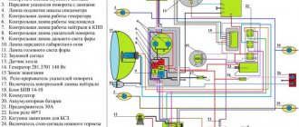
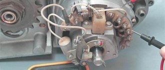
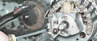
Generator IZH Planet 4
A more advanced generator began to be installed on the new model of the Izhevsk Motor Plant, capable of serving the increased needs of the electrical equipment system, in contrast to the wiring diagram of the IZH Planet 3.
Original factory circuit diagram of the IZH Planet 4 motorcycle generator
Among the design features it is worth highlighting:
- Eight coils placed in the stator slots;
- Serial connection diagram;
- Coating of coil windings with insulating varnish;
- Original fastening to the stator, made using washers and bent petals.
For reference: The rotor is made in a traditional manner, has the design of an eight-pole magnet placed in a special magnetic alloy. Installed on the cone of the right axle and secured with a segment key and an M7 bolt. The generator stator is located under the cover on the right side of the engine and is secured with three bolts.
To identify faults with your own hands, you need an ohmmeter or a universal tester, which can be used to measure the resistance of the windings:
- If the values of the measured resistances differ significantly, it is necessary to inspect the generator stator to detect broken winding leads;
- The reason for unstable operation may also be their short circuit. If possible, identified faults are eliminated by soldering.
Differences from the second Planet
For many modern citizens, the information that domestic motorcycle manufacturers worked tirelessly to improve their models in an era of total shortages may come as a surprise.
Note! The fact takes place, moreover, it is supported by official documents, in particular 1970N04P16-17 - this is the outgoing number of the factory newsletter, which described the changes made.
In the photo - official materials of the Izhmash Design Bureau
The new generation motorcycle received:
- Direction indicator lights are a first in domestic practice;
- Semiconductor relay for controlling direction indicators (installed in the headlight);
- New size of wheels and tires (3.50x18 versus previous - 3.25x19);
- New brand increased capacity battery (old one on IZH Planet 2 - ZMT-6);
- And, of course, more engine power. The power unit now developed 18 hp.
Modifications
But the creator engineers did not stop there and, having released the five-millionth car from the production line, presented a modification of the IZH Planet 3-01.
Mirror and safety arches are the distinctive features of the new modification
Among the innovations it should be noted:
- Rear passenger footrests;
- Roll bars;
- Rearview mirror;
- New steering wheel design.
For reference: The buyer paid for the changes out of his own pocket. In particular, the price for IZH Planet 3-01 was 750 rubles, the version with a stroller was 1140, and the “rural version” was even more expensive. Fortunately, care instructions were included with purchase, which made maintenance easier.
IZH Planet 3-01 with wide wheels of smaller diameter - “rural version”
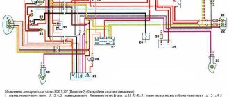
Help for owners of IZH Planet 4
The motorcycle left a good memory of itself among lovers of two-wheeled vehicles. Many of them willingly share tips on restoring and remaking their “iron horses.”
Electrical wiring diagram redrawn by motorcycle “fans” (from the black and white factory one)
Communication on the following topics is especially relevant:
- Modernization of the ignition system;
- Installation of alloy wheel rims;
- Modernization of the instrument panel;
- Troubleshooting electrical systems;
- Installing an alarm system on a motorcycle and altering the wiring;
- Converting the motorcycle electrical circuit to work without a battery;
- Interchangeability of electrical components and compatibility with other brands of motorcycles, for example, with Ural motorcycle wiring diagrams.
Step-by-step guide to installing and adjusting the ignition
To carry out the setup, you need to prepare a special tool, a tester, and a light bulb with two wires. A caliper will be needed as a depth gauge. To set the gap it is convenient to use a special feeler gauge.
1. Voltage tester
2. Caliper for measurements
3. Feeler gauges for setting the gap
Setting up SZ on IZ Jupiter 5 consists of the following steps:
- First open the generator cover.
- To make it more convenient to work, remove the right cover from the crankcase.
- Using the generator bolt, turn the crankshaft clockwise. It is necessary to ensure that the breaker contacts open to the maximum distance.
- Unscrew the screw a little and turn the eccentric. It is necessary to set a gap between the contacts equal to 0.4-0.6 mm. After this, tighten the screw well.
- Rotate the crankshaft in the direction of movement of the clock hand. The piston should be installed at TDC.
- You need to turn the crankshaft in the opposite direction, that is, counterclockwise. In this case, the piston should not reach TDC; a distance of approximately 3.0-3.5 mm should remain. By loosening the screws, you should establish the beginning of the contact closure. After this, the screws must be tightened tightly.
- To determine if the contacts are open, use a test light with wires. One wire must be connected to the breaker hammer terminal, and the other to ground. After turning on the ignition, when the contacts are closed, the light should light up.
- If BSZ is installed on IZ Jupiter, then there is no need to set the gap. To determine the moment you need to use a tester. The device should be set to measure voltage. The probes must be connected to the 2nd and 3rd contacts of the DC. While the modulator is not in the DC, the voltage reading on the tester should be 7 V. At the moment when the modulator is in the DC, the voltage reading should be in the range from 7 to 0 V. At this moment, a spark is formed.
- The procedure must be performed on each cylinder. It is advisable to start adjusting the gap on the left breaker. When the left breaker is configured, you can move on to the right one.
SZ motorcycle IZH
Having learned how to configure the electronic contactless SZ on the fifth model, apply your knowledge to set up the SZ on IZ Jupiter 3.
Loading …
Non-contact ignition on Izh - understanding unclear terms
- BSZ – contactless ignition system;
- Modulator – metal disk (steel 0.8-1.0 mm thick), plate, curtain. Installed on the axis of the ignition timing mechanism (distributor shaft). Produces “generation” of magnetic pulses to the Hall sensor.
- Switch – an electronic device that supplies electrical impulses to the ignition coil;
- A Hall sensor is a device capable of detecting the presence or absence of a magnetic field. If there is a field, a control pulse goes to the switch. The sensor position is fixed.
- The ignition coil is a converter of pulses coming from the switch into high-voltage pulses supplied directly to the spark plugs.
How to check the ignition coil - basic methods
In principle, you can determine the cause yourself, since checking the functionality of the ignition coil is quite simple. To do this you need to remove it. Depending on the car model, you should look for it in the engine area, namely the cylinder block. In order not to harm the electrics, disconnect the negative cable from the battery and the connector on the coil. Next, you need to sketch out on paper exactly how it was installed and, of course, connected. The ones that interest you most are the high-voltage wires; their diagram is extremely important; after sketching it, remove their terminals from the coil.
All that remains is to unscrew four bolts and the part is removed. Then carry out a visual inspection for defects and chips; there should be none. Also clean its body from dirt, because it contributes to the occurrence of large voltage leaks. In order to check the bobbin for breaks, you need to know how to ring the ignition coil; for this you only need an ohmmeter (one of its terminals is connected to the winding input, the second to the output). First ring the primary and then the secondary windings. The resistance on the first should be much lower than on the second.
There is another way to check the ignition coil if the previous methods did not reveal any malfunctions. In this case, it is necessary to connect the primary winding of the bobbin to a DC source (12 V), connecting it to the buttons, they are designed for a current of 20 V. In parallel, connect a capacitor with the same capacitance as in the ignition system. A candle is connected to the second winding, and the source is quickly turned on several times. The resulting crackling indicates the presence of breakdowns. Thus, there is nothing difficult about how to check the serviceability of the ignition coil; the main thing is to monitor its condition, since any malfunctions can lead to very negative consequences. Repair consists of restoring the winding or completely replacing the part; it is inexpensive, fast and reliable.
- Alekhandro_Izyumskiy
- 19 November 2012, 19:10
- v
- Dionisiy_Polhovskiy
- November 20, 2012, 20:49
- v