4 years after the appearance of the second Planet (1966), the factory workers made a number of changes to its design, designed to improve the technical parameters and appearance of the motorcycle. This is how IZ Planet 3 was born, which became a real symbol of freedom for many of our compatriots.
Despite its advanced age, IZH Planet 3 still serves its owners well
Differences from the second Planet
For many modern citizens, the information that domestic motorcycle manufacturers worked tirelessly to improve their models in an era of total shortages may come as a surprise.
Note! The fact takes place, moreover, it is supported by official documents, in particular 1970N04P16-17 - this is the outgoing number of the factory newsletter, which described the changes made.
In the photo - official materials of the Izhmash Design Bureau
The new generation motorcycle received:
- Direction indicator lights are a first in domestic practice;
- Semiconductor relay for controlling direction indicators (installed in the headlight);
- New size of wheels and tires (3.50x18 versus previous - 3.25x19);
- New brand increased capacity battery (old one on IZH Planet 2 - ZMT-6);
- And, of course, more engine power. The power unit now developed 18 hp.
Modifications
But the creator engineers did not stop there and, having released the five-millionth car from the production line, presented a modification of the IZH Planet 3-01.
Mirror and safety arches are the distinctive features of the new modification
Among the innovations it should be noted:
- Rear passenger footrests;
- Roll bars;
- Rearview mirror;
- New steering wheel design.
For reference: The buyer paid for the changes out of his own pocket. In particular, the price for IZH Planet 3-01 was 750 rubles, the version with a stroller was 1140, and the “rural version” was even more expensive. Fortunately, care instructions were included with purchase, which made maintenance easier.
IZH Planet 3-01 with wide wheels of smaller diameter - “rural version”
Motorcycle service
Unlike other models, both domestic and foreign, IZH Jupiter 3 is distinguished by enviable survivability.
Here are a few instructions for resuscitating a motorcycle that has stood motionless:
- It is enough to replace or clean the candles yourself;
- Adjust the ignition;
- Replace high-voltage wires from the coils with spark plugs;
- Change the engine oil;
- Install a new battery or charge the existing one.
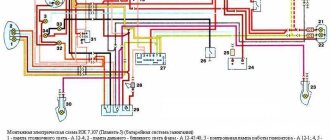
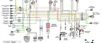
Modern scheme, more understandable to the younger generation
And it will start and drive. And this is its distinctive feature, which is well known to the generation of the 80s. You can restore the old paintwork, reupholster the seat, or polish the chrome parts to a shine later, the main thing is its durability.
Advice: wiring IZ Jupiter 3 after long-term storage also requires close attention. Inspect it for abrasions and damage to the insulation. If any, replace the wires. Don't repair, just replace.
In the photo - the restored IZ Jupiter 3 (right) looks no worse than modern models
In the video below you can get acquainted with the features of this model. It should be noted that the cost of restoration is quite affordable for most, and the difficulty lies only in the lack of spare parts and the need to modify those found from other models.
Distinctive features of electrical equipment
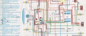
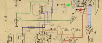
The wiring diagram used on IZ Planet 3 was traditional, and the main parameters of the electrical equipment are presented below in the table.
| Ignition system | Battery, ZMTR-10 |
| Mains voltage | 6 volts |
| Electricity source | Generator G-35M7 (later replaced by a modified G-36M8), 45 W |
| Ignition coil | IZH 56 |
| Voltage regulator relay | IZH RR-1 |
| Electrical wiring IZH Planet 3 | Single-wire, with “-” output to ground |
Colored original diagram (clickable)
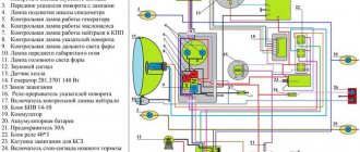
Lighting devices
The following lighting devices were installed on the IZH Planet 3 motorcycle:
- Left and right direction indicators with A6-6 lamps;
- Turn signal switch P201;
- Turn signal relay RS-419;
- Brake light bulbs A6-15;
- Side light bulbs A6-2;
Appearance of instruments and controls
- Light mode switch with sound signal button P200;
- Transmission position sensor (neutral) with warning lamp A6 0.25;
- Headlight lamp A6-32+32;
- Indicator lamp A6 0.25 generator operation;
- Side light lamp A6-2 (front);
- Speedometer scale illumination lamp A6-1;
Headlight and direction indicators
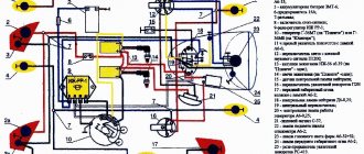
Attention! For lovers of the “original” and authenticity, the photo below shows the “native” black and white wiring diagram of IZH Planet 3 with a breakdown of all the elements.
For connoisseurs of “antiques” - the original diagram from the instruction manual
Lighting devices for models with a stroller
Added to the existing list:
- Stroller brake light lamp A6-15;
- Stroller size lamp A6-2;
- Right direction indicator for stroller A6-6;
- Front side light of stroller A6-2.
Option with stroller
Note! The standard wiring of the IZH Planet 3 provided for disconnecting the sidecar for operating the motorcycle without it in a two-wheeled version. At the same time, the connecting terminals required care.
In the presented video you can watch the repair of an old motorcycle, which received a new life in capable hands. According to the author of the video, complete restoration cost him the equivalent of $130. Moreover, he did most of the work with his own hands.
MY MOTORCYCLE
LEDs have recently become much more dominant than conventional light bulbs and other lighting elements. They didn't leave motorcycles aside either. Quite a few people are trying to convert their turn signals to LED ones, and the motorcycle manufacturers themselves (not all of course) are slowly introducing these economical illuminators. But in this post we will talk specifically about LEDs in corners.
Standard turn relays come with two and stirrup terminals. If your motorcycle has three, consider yourself lucky: such a relay does not care which lighting devices it interacts with. But two-pin ones do not want to coexist with LEDs.
To understand why, let's look at how simple devices work, like those that were installed on Soviet equipment and old scooters. In them, the blinking of the lamps is controlled by a metal thread located in the relay housing. When the turn signals are turned off, it compresses the contacts; when the indicators are turned on, current passes through the contacts and the thread. The thread heats up, stretches, a gap forms between the contacts, and accordingly, the current stops flowing and the light bulbs go out. The filament cools, shortens and compresses the contacts - the lamps light up again... If one of the lamps burns out, the current consumed is not enough to heat the filament - and the surviving lamp shines constantly. Some modern two-terminal electronic relays behave the same way. In conjunction with others, the surviving lamp, on the contrary, begins to blink very quickly and thereby, as it were, warns the driver of a malfunction. But LEDs consume several times less current than a light bulb - that’s why LED turn signals in an electrical circuit with a two-pin relay either stay on constantly or blink like crazy. But don't be discouraged - it's not difficult to pacify crazy electronics.
METHOD ONE: DECEPTION. The simplest and most unsuccessful way is to connect standard lamps parallel to the new turn signals and hide them out of sight somewhere deep inside the motorcycle. Please note that the power of the lamps is high, and while you wait with the turn signals on for the traffic light arrow to light up, the lamps will have time to heat up to a hundred degrees or more and melt the plastic surrounding them. And besides, they need to be securely fastened - otherwise the vibration will either break the glass or break the filament.
Deceive wisely! I’ll tell you how: using additional resistors. They are also installed parallel to the turn signals, and one on the right and left sides of the motorcycle is enough. You can select resistors by trial and error (they are inexpensive) from 20-watt resistors with a nominal value of 5-20 ohms - so that the lamps blink approximately 90+20 times per minute (according to GOST). But radio engineering parts are not designed to operate under vibration, and if they are not secured properly, they will quickly fall apart. It is advisable to install the resistors outside - here they will be cooled better and will not melt anything. Unless, of course, you manage to attach them to the plastic. Another thing is that “overboard” they can be damaged by dampness. In addition, they must be carefully isolated from ground so that a short circuit does not occur.
There are special additional resistances on sale. LED turn signal kits from some companies already contain such parts; they are well insulated, but keep in mind that parts with a ceramic body are short-lived (first photo): they can fall apart in just a year. Metal cases are strong, reliable, they have eyes for fastening and fins for cooling. Everyone likes these parts... except for the price - it is comparable to the cost of turn signals. In addition, additional resistors negate an important advantage of LEDs - low current consumption. Maybe this is not so important for a “liter” superbike, but for a scooter with its weak generator it won’t hurt to save an extra ten watts.
METHOD TWO: REPLACE THE RELAY . If you are an electrician, take the risk of replacing a two-pin relay with a three-pin one yourself. Connect one of the three contacts to the ground of the motorcycle. Find out which one exactly by studying the electrical diagram of the motorcycle for which the device is intended “according to the state”. Usually, electronic turn signal relays are very reliable - you can safely buy them at “showdowns”. But when purchasing, still ask to check their performance, and at the same time you will find out which output is connected where. During installation, you will have to resolder the connector of your device. It’s easy to find the “plus” in it - turn on the ignition and connect one by one to both wires a voltmeter or a light bulb, connected with the second terminal to ground. The wire on which there is no “plus” goes to the switch on the steering wheel. You will have to figure out how to connect it yourself - no instructions are included with them.
METHOD THREE: RECONFIGURE . And if you are also friends with a soldering iron (it’s better, of course, for it to be friends with you), you can do it even simpler. Buy a turn relay from Zhiguli with index 495.3747A, using a thin screwdriver (it’s easier to work with two) disassemble the housing, as shown in the photo. Try not to skew the base so as not to break anything. If the wires leading to the terminals come off the board, don’t worry: soldering them back in place is a matter of minutes. The main thing is not to damage the board. Inside you will see a mechanical relay, a microcircuit and a capacitor. You will also see resistors, but you don’t need to touch them. Typically the capacitor capacity is 2.2 µF and it is rated at 50 V - all this is written on the case. In order for the turn signals to blink at the “correct” frequency, the capacitor must be replaced with another one, approximately twice the capacity, for example, 4.7 uF and also 50 V (about 10 rubles). When you start soldering the parts, pay attention to where the “minus” is drawn on the body of the standard capacitor: the new one must be soldered in exactly the same way! After assembly, it is advisable to seal the relay housing connector - lubricate it with silicone sealant. But that's not all. Usually, the Zhiguli relay does not want to just work with LEDs - the relay does not click, the turn signals do not turn on. Solder parallel to one of the left and right indicators with a resistance of 2, or maybe 1 kOhm with a power dissipation of at least 0.25 W. The current flowing through these resistors is negligible, and they practically do not heat up. Therefore, the parts can be attached with electrical tape or heat shrink casing directly to the wires. And the turn signals will begin to work in accordance with GOST: immediately after switching on, they will light up for a while, and then blink at the required frequency.
The main disadvantage of the redesigned relay: it will no longer notify the driver that the turn signal has burned out. In addition, it is equipped with mechanical contacts, and they, like any mechanics, are less reliable than electronics. But this drawback can be neglected: “LED” currents are too small for the contacts to burn.
METHOD FOUR: DO IT YOURSELF RELAY:
If you like to tinker in principle, build a fully electronic turn signal relay. It has no mechanical contacts and will work equally well with light bulbs and LEDs. But this relay also has a drawback: it immediately starts working when the ignition is turned on. It is impossible to predict whether the turn signals will light up immediately when turned on with the switch on the steering wheel or a little later. The homemade relay is based on the NE555 timer (it can be replaced with a domestic analogue KR1006VI1, but I cannot guarantee reliability). It controls the power field-effect transistor IRFU5305. It can be replaced with a part with a P-channel of similar properties. Moreover, resistance is only needed if you install an analogue one. IRFU5305 works just fine without resistors. Resistances R1, R2 and capacitor C1 must be selected experimentally - the blinking frequency of the turn signals depends on them. The only requirement: the resistance of resistor R1 must be 10 times less than that of R2 When selecting parts, the starting point can be the values of R2 200 kOhm, and C1 - 2.2-4.7 μFx50 V. The lower the resistance value and capacitance of the capacitor, the more often direction indicators flash. All this can be placed in the housing of any automotive relay - at the nearest service station, electricians will probably have one that you wouldn’t mind giving as a gift.
In addition to these tips, I think there are still plenty of options for converting turns and relays to LEDs that folk craftsmen come up with. My friend changed and redid the turns on his sportbike himself and he succeeded. I’ll try to post the information for you on the website someday. Also, if you have. Dear site visitors, if you have your own options, don’t hesitate to write.
Author of the main technical material Andrey SUSLOV; source MOTO Magazine.
Maintenance
The owner can independently perform some maintenance procedures:
- check the motorcycle generator if the battery loses charge;
- set the gap between the breaker contacts;
- adjust the quality of the sound signal.
The need to inspect and adjust the wiring arises if:
- the motorcycle moves in the rain for a long time, as this causes oxidation of the contacts;
- a motorcyclist rides in an area with a lot of vegetation that damages wiring;
- The driver rides in snow in winter, which can stick to electrical wiring parts and damage them.
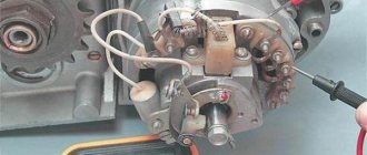
Self-check of the Planet 5 motorcycle generator in case of loss of charge
The cause of loss of charge in the IZH Planet 5 battery is most often a breakdown of the generator.
To check it yourself you need:
- multimeter device;
- straight screwdriver.
Step-by-step instruction
The following steps must be followed:
- Disconnect the wires from the battery and remove the generator cover.
- Disconnect the top 5 wires from the generator, first unscrewing their fastenings. In order not to mix up the wires during assembly, it is worth marking them.
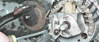
- Measure the winding resistance using a multimeter in ohmmeter mode. To do this, you need to touch the body with one probe, and the other should be connected in turn to the 3 wires of the winding. There should be no short circuits, as indicated by the inscription on the multimeter screen.
- Test the resistance between the stator contacts: you need to touch them one by one with the multimeter probes. The value on the screen should be 8 ohms.
The presence of a short circuit in the 3rd stage or a discrepancy in the indicators in the 4th will indicate problems with the generator.
Photo gallery: stages of checking the IZH Planet 5 generator in case of loss of charge in pictures
How to correctly set the gap between the contacts of the breaker?
In order to set the gap between the breaker contacts, you will need:
- straight screwdriver;
- wrench 10;
- candle key;
- probe 0.4 mm thick (+/– 0.05 mm).
Next, you need to follow the steps sequentially:
- Place the motorcycle on a stand and place the gearbox in neutral.
- Remove the right crankcase cover and unscrew the spark plug.
- Using a 10mm wrench, grab the generator rotor mounting bolt and turn the crankshaft to a position where the contacts are as far apart as possible.
- Loosen the screw securing the contact.
- Place the probe between the contacts and adjust the tightening of the eccentric screw until the probe passes the contacts with little resistance.
- Tighten the contact fixing screw.