Electrical diagram of the car DNEPR - MOTORCYCLE
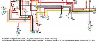
Electrical circuits of Dnepr motorcycles of various modifications - Dnepr MT-10, Dnepr 11, Dnepr 16 other models. To enlarge the diagram, click on it.Electrical circuit of the motorcycle Dnepr MT-10
Electrical circuit of the motorcycle Dnepr MT-10 36
1 — left turn signal light Dnepr MT-10, 2 — lamp A12-21; 3 - headlight; 4 — lamp A12-4 for side and parking lights; 5 — lamp A12-45-40 high and low beam; 6 — right turn signal lamp (not connected on a motorcycle with a sidecar): 7 — speedometer; 8 — lamp A12-1 speedometer lighting; 9 — indicator lamp for direction indicators; 10 — warning lamp for emergency oil pressure; 11 — high beam warning lamp; 12 — generator warning lamp; 13 — neutral sensor warning lamp; 14 — instrument panel; 15 - central switch; 16 — direction indicator switch; 17 — turn signal switch; 18 — contact plug; 19 — emergency oil pressure sensor; 20 - light switch; 21 — front light of the stroller 22 — lamp A12-21 for side light and brake signal on the stroller; 23 — fuse block; 24 - generator; 25 - signal; 26 — relay-regulator: 27 — brake signal switch, 28 — Dnepr MT-10 switch; 29 — battery; 30 - breaker; 31 — ignition coil; 32 - high voltage wire; 33 - spark plug tip; 34 — spark plug; 35 — rear light of the stroller; 36 — headlight of the Dnepr MT-10 motorcycle; 37 - lamp A12 15 brake signal; 38 - lamp A12-3 for the side light of the license plate lighting.
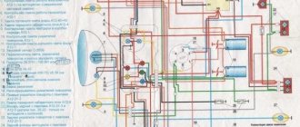
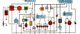
Electrical circuit of the motorcycle KMZ-8.155 Dnepr-11 and KMZ-8.922 Dnepr-16
Electrical circuit of the Dnepr-14 motorcycle
1 – emergency ignition switch 2 – day-night switch 3 – connector blocks Dnepr 14 4 – right turn indicators with lamp A12-21 (on a single motorcycle) 5 – handbrake brake light switch 13.3720 6 – speedometer scale backlight lamp A12-1 7 – indicator lamp for direction indicators А12-1 8 – indicator lamp for emergency oil pressure А12-1 9 – indicator lamp for high beam 10 – headlight lamp А12 –45+40 11 – side light lamp in the headlight А12-4 12 – ignition switch 141.3704 13 – left direction indicators with lamps A12-21 14 – relay-interrupter of direction indicators RS 427 15 – direction indicator switch 16 – light switch Dnepr 14 17 – right direction indicators with lamps A12-21 (on a sidecar) 18 – lamp A12-8 of the front side light (on the sidecar) 19 – emergency oil pressure sensor 20 – fuse block 21 – relay-regulator 33.3702 22 – indicator lamp for generator operation A21-1 23 – indicator lamp for neutral in the gearbox A21-1 24 – sensor for switching on the neutral warning lamp 25 – sound signal S-205 26 – ignition coil B-204 27 – breaker PM-302A 28 – horn button 29 – double-filament lamp A12-2+6 for high beam and brake light (on a wheelchair) 30 – foot brake brake light switch 31 – brake light lamp A12-21 32 – tail light lamp A12-5 33 – maesa switch 34 – battery 6MTS-9 or 2KhZMT-6 35 – socket (only on Dnepr -16") 36 – generator G-424 and rectifier 37 – relay RR-330.
CAR ELECTRONICS REPAIR
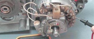
Dnepr motorcycle generator wiring
Motorcycle DNEPR-11.
Electrical wiring Sources and consumers of electrical energy, as well as auxiliary devices, are connected to each other by wires. For ease of installation, the wires (except for high voltage wires) are connected into bundles. The wires are connected to each other and to consumers by metal connections, protected from ground faults by rubber tubes, the ends of the wires are protected by rubber caps.
The wiring harnesses are attached to the frame of the motorcycle and the side trailer with tapes and secured with clamps.
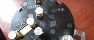
All lighting devices are protected by fuses. The PR11M fuse box is installed on a bracket under the instrument panel. The block is equipped with 15 A fuses (4 pcs.).
Upper fuse No. 1 protects against a short circuit in the LIGHT switch circuit. Fuse No. 2 protects against short circuits in the side light circuit. Fuse No. 3 protects the horn circuit, the hand and foot brake stop switches, and the “neutral” and “oil pressure” indicator light circuit from short circuits. Fuse No. 4 protects the turn signal relay circuit from short circuiting. Instead of a 15 A fuse, a 10 A fuse can be installed in this circuit.
Methods for detecting faults in electrical circuits and components of a motorcycle
A malfunction of the electrical circuit is indicated by a failure in the operation of sources and consumers of electricity (generator, relay regulator, instrumentation, lighting, etc.).
In this case, the following malfunctions may occur: breakage or loss of contact in the wires connecting the consumer to the source of electricity;
malfunctions of fuses or switching equipment (ignition switch, switches, sensor, etc.);
short circuit or overload in the circuit, causing the fuses to trip.
Before you start checking the electrical circuit, you need to make sure that the fuse is working. It can be checked using a test lamp - connect one end of the wire to the “+” of the battery, and the other to one of the sides of the fuse being tested. Connect the free end of the fuse through a test lamp to the “—” battery or to the motorcycle body (“ground”). If the fuse is good, the lamp will light.
To check the electrical circuits you must: turn on the ignition switch;
turn on the circuit being tested with consumers.
If the consumer does not work, but the fuse is good, then the circuit or consumer is faulty. Checking the presence of voltage should begin with the consumer terminals. The following options are possible:
there is no voltage at the consumer terminals (the control lamp does not light up) - check the serviceability of the electrical circuit from the consumer to the source;
There may be a wire break or lack of contact in the connections. In this case, depending on the malfunction, you need to tighten the contacts or replace the wire;
there is voltage at the consumer terminals (the control lamp is on) - check the serviceability of the consumer (replace burnt out lamps).
If the fuse blows, there is a short circuit in the circuit. The problem must be found and corrected before the ignition switch or test circuit is turned back on. The check is carried out in the same order as in the previous case.
When checking the voltage on the primary winding of a high-voltage coil, the breaker contacts must be closed.
Determining possible malfunctions of the generator and voltage regulator
If the control lamp for the operation of the generator and voltage regulator does not light up when the ignition is turned on, then first of all you need to check the reliability of the terminal connections on the voltage regulator and the battery, the reliability of the connection of the voltage regulator body to ground, and the presence of voltage at the “+” terminal of the voltage regulator.
If this test does not give a positive result, it is necessary to check the serviceability of the control lamp circuit from the instrument panel to the “LK” terminal of the voltage regulator. To do this, disconnect the wire from the “LK” terminal on the voltage regulator, turn on the ignition and connect it to the disconnected wire with the “+” terminal of the voltage regulator. If in this case the lamp does not light up, even if there is voltage at the “+” terminal, you should check the wires, the reliability of the contacts and the test lamp. If the lamp lights up when shorted, the cause of the malfunction is the voltage regulator, which needs to be replaced.
Excursion into history
It is generally accepted that the prototype of the Urals was the German motorcycle BMW R-71, the drawings of which were officially purchased in the fortieth year of the last century.
After studying and developing the technical documentation, the domestic M-72 motorcycle was born, which had some differences from the prototype:
- The model was equipped with a double-disc clutch (in German, a single-disc clutch was used);
- The final drive ratios were increased, which increased its cross-country ability in off-road conditions;
- The wiring diagram of the Ural motorcycle was chosen to be single-wire (on the German prototype it was two-wire);
- The entire electrical circuit was built on a voltage of 6V (later switched to 12 volts);
- The ignition timing for different engine operating modes was given manually.
The wiring diagram for the Urals provided for manual setting of the ignition timing
A feature of domestic motorcycles was the ease of do-it-yourself maintenance - any breakdown or malfunction could be solved in the field.
Over the course of several years, no more than 7,000 copies were produced at all enterprises that mastered the production of motorcycles:
- Moscow Motorcycle Plant (MMZ had the most massive production of the M-72);
- Gorky Motorcycle Plant (GMZ);
- (Leningrad);
- Kiev Motorcycle Plant (KMZ);
The main production of Ural heavy motorcycles was launched at the Irbit motorcycle plant, located in the Sverdlovsk region, where MMZ production equipment was evacuated at the beginning of the war.
The factory instructions describe in detail the power unit of the Ural motorcycle
For reference: The Irbit motorcycle plant, formed on the territory of the brewery in November 1941, is considered to be the ancestor of the M-72 motorcycle, called “Ural-1”. Throughout the years of its activity, its only specialization was the production of heavy motorcycles. And all the military videos featured exclusively his products.
Find out also about the features of the 16-valve VAZ 21103 wiring.
Period 1941-1954
Having appreciated all the advantages of the motorcycle in the conditions of hostilities, it was decided to increase their production several times. In 1942 alone, the Irbit Motorcycle Plant produced almost 10,000 Ural-1 motorcycles. In the post-war years, the annual target was 20,000 motorcycles.
The first batch of motorcycles from the Ural Irbit Motor Plant entered the Red Army in February 1942
The main customers were:
- RKKA (Workers' and Peasants' Red Army, later renamed the Soviet Army);
- Law enforcement service (police);
- Consumer cooperation (in the post-war period);
- Population (did not go on sale until the mid-50s).
Motorcycle M-72 Ural model 1942
For reference: Over the two decades since its release, the motorcycle has proven its worth as a mobile vehicle, most suitable for use in off-road and urban environments.
Period 1955-1964
The wiring of the Ural motorcycle also performed well - if at first the designers had concerns about loss of contact due to possible corrosion of the metal frame, then operation showed the reliability of the single-wire electrical circuit.
Single-wire color wiring diagram for a Ural motorcycle with a sidecar
However, with the release of the transitional model IMZ M-61 and, on its basis, the new Ural model M-62 (in 1961), the following were modernized:
- Transmission,
- steering;
- ignition system.
In particular, automatic ignition timing was introduced, since the motorcycle received a new power unit, and the old manual control of the timing advance did not meet the technical requirements.
The new electrical wiring for the Ural motorcycle connected into a single system:
- Battery model 3MT-12 with a voltage of 6V;
- Relay-voltage regulator model PP-31;
- Generator brand G-414;
- Distributor chopper with ignition advance system PM05;
- Ignition coil model B201.
Color diagram: Ural motorcycle wiring with symbols
In just a couple of years, Ural modifications appeared in the production program of the Irbit Motorcycle Plant:
- IMZ M-61 (transitional model for testing a new overhead valve engine);
- M-63 “Ural 2” (the frame was modernized and a new exhaust system was introduced, which made it possible to increase ground clearance);
- M-66 “Ural 3” (the wiring diagram for the Ural motorcycle was replenished with direction indicators and new side lights);
For reference: a large number of models under the Ural brand and alphanumeric indices often create confusion. For example, the wiring diagram of the Ural 4320 implies the electrical system of an off-road truck, and the wiring diagram of the Ural 5557 implies its modifications, and not one of the varieties of a heavy motorcycle.
See also the Moskvich 412 wiring diagram.