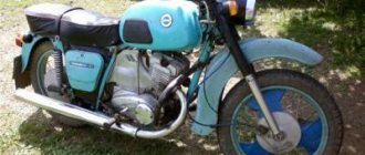
The road version of the IZH Planet 5 motorcycle differed favorably from other domestic analogues by the use of an oil pump, which made it possible to abandon the scheme for pre-mixing fuel with oil.
In addition, subsequent modifications were distinguished by their contactless ignition system, independent of the battery, and modified kinematics.
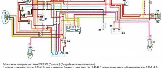
Battery wiring diagram IZH Planet 5
This allowed:
- To set the motorcycle in motion “from the pusher” - by turning on the ignition, the owner engaged second gear and, using his own efforts, pushing the motorcycle forward, started the engine;
- Operation without a battery was possible during daylight hours (a battery was still required for the side lights and headlights to operate).
Generator - serviceability check
Checking the serviceability of the generator can be done on a motorcycle without disassembling the generator.
To carry out the work you will need a multimeter.
1. Place the motorcycle on the center stand or side stand.
2. Disconnect the battery by removing its fuse.
3. Remove the right cover of the power unit.
4. 6mm
unscrew the nuts securing the five “upper” wires of the generator. In order not to confuse the wires during subsequent assembly, we mark them or tie them with thin wire so that we get a cable.
5. Check the short circuit of the stator windings to ground. To do this, touch the probes of the multimeter to the generator housing and alternately the three terminals of the windings. The ohmmeter should show infinity.
6. Check the stator windings for breaks. To do this, touch the probes of the multimeter in turn to all three terminals of the stator windings. The resistance should be about 8 ohms.
7. Check for a short to ground in the excitation (rotor) winding. To do this, touch the probes to the generator housing and one of the terminals of the brush assembly. The ohmmeter should show infinity.
8. Check the field winding (rotor) for open circuit. To do this, install probes on both brushes. The ohmmeter should not show infinity.
Source
Installation of an automotive diode bridge (horseshoe) and a voltage regulator with a brush block on an IL
List of required parts:
1. Diode bridge generator BPV 56-65-02-G (“with one wire”) or BPV 56-65-01 (“with two wires”).
2. Voltage regulator Y212A11.
3. 100 ohm resistor with a power of 1 Watt. (Not required)
Note
: the difference between BPV 56-65-02-G and BPV 56-65-01 is that the first has a male connector made in the housing (and we will have to break it out and solder a wire instead), while the second diode bridge has it made in the form of an additional wire.
Voltage regulator YA212A11
Installing a horseshoe on a generator:
We take the generator and remove everything unnecessary from it:
Next we need to cut out a place to become a horseshoe, leaving an uncut part in the middle for the rigidity of the structure:
Then we need to extend the stator wires. It is not necessary to remove the stator from the generator housing, it will just be more convenient to solder, and it will be convenient to carefully insulate it.
Now you need to cut off the excess from the horseshoe so that it fits normally into the cut out generator housing and when the right cover is installed there is no short piece of the top plate with the inner wall of the cover. Break off the terminal (male connector) that sticks down. Also replace the inner plate (to which small diodes are soldered) with a wire, in case there is also no shorty with the generator body:
Next, you need to attach the horseshoe to the generator. To do this, we drill holes for the bolts on the horseshoe opposite the threaded holes on the generator, and make a larger hole in the top plate so that the head of the bolt can fit through. So that when we clamp the bolt, it does not touch the top plate (Don’t forget that this is + and it should not short-circuit with mass anywhere!):
And at the same time, do not forget to place an asbestos gasket under the diode bridge so that the diodes do not heat up from the generator, since they do not like overheating.
Motorcycle generator IZH 281.3701
On IZH motorcycles starting from the fourth Planet, an alternating current generator 281.3701 is installed, which is a modern three-phase electric source of electricity. This source is used to power electrical lighting, alarm, and ignition devices. Together with the rectifier, the BPV-14-10 regulator recharges the battery. The generator consists of two parts, a stator and a rotor.
services and repairs
The power source on both IZh 5 and 6 motorcycles is a battery and a 3-phase alternating current generator. The algorithm of actions is as follows: Make the adjustment with the low beam on in accordance with the screen markings in Fig. When the clearance is correctly set, the engine idles stably. It’s quite easy to check it yourself, the test scheme is as follows: Disconnect the battery, then remove the generator cover. The switch is housed in a hermetically sealed plastic case, which prevents moisture from entering. The problem with Planet 5 motorcycles is the lack of a separate fuse box, and often in the event of a malfunction it is necessary to inspect the entire electrical wiring. On both IZH 5 and 6 bikes there may be problems with the sound signal; it may sound weaker. During operation it does not require maintenance and cannot be repaired. Some owners remove the battery themselves or remove the main fuse if the electrical circuit is damaged and there is no time or desire to deal with it. Spark plug tip for IZH 7 motorcycles. You can also download for free and via a direct link an archive with IZH diagrams. Then you should check the resistance between the stator terminals by touching them one by one with probes.
But the IZ wiring diagram is unlikely to be useful for conversion - practically nothing from the namesake car fits the motorcycle. Simple wiring for a motorcycle part 2
Generator stator 281.3701 for IZH motorcycles
The stator is installed on the right half of the engine crankcase and secured with three bolts. The frame is made of special sheet steel. It has 18 tooth-shaped places for winding phase windings. The phase winding is made of one solid wire with a diameter of 0.9 mm and is wound on six teeth. Each tooth has 20 turns of copper wire wound around it. There are six teeth in total on the winding, so 120 turns are wound. There are three such windings. The connection of the windings is made with a star. The terminals of the phase windings are connected to the terminals of the comb.
The generator stator is covered with an aluminum alloy cover. There are special places on the cover and threaded holes where the carbon brush holder is installed. A breaker with a capacitor to produce a spark. Special comb for connecting wires.
Generator rotor 281.3701
The generator rotor 1 is located inside the stator. It is installed on the crankshaft using bolt 3 and key 5. An excitation winding 6 is wound on the rotor core with a copper wire with a diameter of 0.56 mm, 600 turns are made. The winding resistance is approximately 6.4 ohms. For contact with the winding, two copper rings 2 and carbon brushes are used. They perform the work of a current collector.
How to remove the generator rotor 281.3701
The breaker cam 4 is installed in one position on the rotor shaft in a special socket and secured with a mounting bolt 3. Under this cam there is a thread that is intended for removing the rotor from the crankshaft. To remove the rotor, you need to screw the screw from the chain disassembly device into the thread. The device is located in the motorcycle tool. If there is no screw, you can use a regular bolt with an M10 thread. The only condition for the thread must be at least 70 mm. Turn until the screw rests on the crankshaft. Then we apply more force to tighten it, and the rotor is removed from the shaft.
If something is wrong.
- Disconnect the relay regulator (remove the connector). Let's take a tester.
- We set the tester to measure resistance. We check the resistance between ground (engine) and the generator wires (three wires, usually yellow). It shouldn't exist. If at least one has it, your motorcycle's alternator has burned out.
- We check the resistance between the generator wires, the resistance should be the same, about 1 - 3 ohms. If it is more or not the same, your motorcycle's alternator has burned out.
- We set the tester to measure alternating voltage. We start the motorcycle, measure the voltage between the generator wires, it should be more than 18 volts at idle, and more than 40 volts at 3000 - 4000 rpm. If there is no or different voltage, your motorcycle's alternator has burned out.
- If the check in points 2, 3 and 4 went well, most likely your motorcycle has a faulty Relay - Regulator or, which also happens, a wiring fault (clean all terminals, check the integrity of the wires, connections to ground). If your motorcycle's generator burns out, this is the place for you: Rewinding the generator with your own hands.
Our service will help you check the charging of your motorcycle.
Check the integrity of wires and connections.
They will eliminate all problems associated with charging the motorcycle.
Generator care
Comes down to visual inspection and cleaning.
First of all, you need to pay attention to parts subject to wear. The carbon brushes of the current collector wear out faster than other parts. They require regular inspection and are replaced if worn. The slip rings of the slip ring must be kept clean. You cannot clean it with sandpaper or needle files. You can use the finest glass sandpaper.
The breaker contacts are periodically checked for the gap value specified in the instructions. For Planet 4 the gap is 0.4 - 0.6 mm. In case of burning, the contacts are leveled and then polished to a mirror finish.
Generator faults
Here we will consider only the malfunctions of the generator IZH 281.1701. First, let's write down the symptoms of a motorcycle malfunction. The next entry will be a possible generator malfunction.
1. The indicator lamp in the instrument panel does not light up. — The generator brushes began to move poorly, the contact between the brush and the ring was lost, or the wire at the brush broke.
2. The control light is on all the time. — The excitation winding has failed. The generator is not working.
3. Engine light is low at medium speeds. — A short circuit occurred in the phase windings of the generator stator.
4. Interruptions in engine operation. The spark is not constant. — Incorrect contact adjustment. The capacitor has failed.
5. Engine power has dropped. — The adjustment in the contacts has gone wrong. The ignition is not installed correctly.
6. The engine does not start or stalls quickly. — Conductive debris has entered the contacts. The capacitor may be faulty.
Source
Checking the motorcycle's charging.
- We take a tester and set it to measure constant voltage (if there is a gradation of measurements, set it to 20 V). We measure the battery with the motorcycle not running. A fully charged battery is 12.8 - 12.9 volts (if less, it is advisable to charge the battery so that further measurements are correct, and also check the battery - you can read how to do this in the article: How to check the battery .)
- If the battery is serviceable and infected, we proceed to check the charging of the motorcycle. We measure the voltage on the battery with a tester, with the motorcycle running (idling, without consumers turned on: lights, heated handles, etc.), the voltage should be 13-15 volts. If the motorcycle charging test does not meet the criteria, move on.
- We turn on only “natural consumers” (lights), the voltage should be at least 12.8 volts (ideally, about 13.5 volts). If less, something is wrong.
- We turn on all consumers (additional equipment), if the voltage drops below 12.8 volts, try raising the idle speed to 1000 - 1100, the voltage should be at least 12.8 volts. If it is smaller, the generator does not pull all consumers (additional equipment) and may burn out.
- We give the gas 3000 - 4000 revolutions, the voltage should rise to 13 - 15 volts with all consumers turned on. On some motorcycles, the voltage rises to a maximum at 3500 -4000 rpm, and at higher rpm it drops, but not more than 13 volts (this is due to increased load at high rpm: the injectors begin to consume more power (they are open almost all the time), this is normal ). If less, something is wrong.
Motorcycle generator tech IZH Planet 5
Izh Moto Club post pinned
For those who don’t know, IZH-Planet motorcycles had a factory contactless ignition system. Yes, yes, exactly, FACTORY. On the motorcycle Izh-Planet 5-01, IZh - Planet 6, a 7.107 - 3701 single-phase alternating current generator with excitation from permanent magnets is installed. The generator rotor is installed on the right axle shaft of the engine crankshaft, the stator is installed in the generator cover or on the crankcase through an adapter. The stator has two separate windings: charging and power. The charging one is connected to the switch and serves to power the engine ignition system, the power one - through the rectifier - the regulator provides power to lighting, alarm devices and battery charging. The generator does not have sliding contacts or rubbing parts; its maintenance is reduced to monitoring the condition of electrical insulation, wire connections and the reliability of the rotor and stator fastenings. The switch is the “brains” of the ignition, replacing the breaker we are used to. Provides automatic ignition timing. Technical characteristics: Rated voltage - 14 V Rated power - 70 W Initial minimum power output frequency - 1700 rpm Initial current output frequency - 970 rpm Maximum power - 105 W Maximum rotor speed - 6000 rpm
This ignition can only be installed on the crankcase from a motorcycle IZH-P5-01, IZH-P6, provided that you have a switch, ignition sensor, BPV 21-15. Such an ignition is extremely rare on sale, as are the switch, ignition sensor and BPV 21-15. An analogue of BPV 21-15 is RNM-1, but more on that later. 1 Photo - ignition sensor. 2.3 Photo - generator IZH-P6 on the left, generator IZH P5-01 on the right.
Source
Features of electrical equipment
Models of IZH motorcycles are as unified as possible. The wiring diagram for IZ Jupiter 2 is not much different from later versions of the IZ motorcycle. There are external differences. For example, the Planet 5 bike has one cylinder, and the Jupiter 5 has two.
The first 12-volt motorcycle was the IZH Jupiter 4. The wiring diagram for the IZH Jupiter 5 and the wiring diagram for the IZH Jupiter 3 differ in components.
Wiring diagram IZ Jupiter 5
The bike of the fifth Jupiter has a contact SZ, which is powered by a battery, so the operation of the vehicle is highly dependent on the state of charge of the battery.
If charging is insufficient, the following problems occur:
- the motor runs intermittently;
- the engine starts with difficulty;
- At low speed the battery is discharged.
These problems can be eliminated by switching to BSZ. Any electrician can handle this task (the author of the video is Viter Electronic).
How to make the transition to contactless SZ?
To switch to contactless SZ, motorcyclists use parts from other motorcycle models. When upgrading the generator set, the wiring of the IZH Jupiter 5 remains unchanged. Minor alterations concern the electrical circuit of the IZH. After changes, the battery is used to service auxiliary equipment. To switch to BSZ, parts are taken from Planet 5 and the VAZ 2108 car.
The following changes are being made to the electrical circuit of IZH:
- install 2 Hall sensors from the eighth VAZ model;
- 2 VAZ electronic switches must be connected to the sensors;
- each of the cylinders serves a commutator-sensor pair;
- You need to add two more ignition coils to the circuit.
SZ after modernization
On the electrical circuit of the IZH motorcycle, the components are marked with numbers:
- Spark plug.
- Ignition coils from Planet 5.
- Switches.
- Hall sensors.
- Egnition lock.
- Battery.
For the created ignition system, it is necessary to modify the IZ Jupiter 5 generator, the circuit of which will not require major changes.
How can I modify the generator?
The presented modernization option is advantageous in that it does not require the purchase of a new generator that will service the new ignition system.
Recycled generator design
All you need to do is follow these steps:
- make a modulator-breaker of an electrical circuit;
- install a breaker on the rotor shaft or generator.
You can create a modulator with your own hands. To do this, you need to take a metal plate and drill a hole in it for the fastening bolt. The manufactured part will serve as a modulator-chopper.
Homemade modulator for interruption
The modulator is connected as follows:
- install the modulator plate (2) and tighten it with the bolt (3), but not all the way;
- by rotating the crankshaft, you need to ensure that the piston is at top dead center;
- Next you need to set the ignition timing;
- Now you can tighten the mounting bolt on the plate.
Hall sensors (1) are installed together with the modulator.
Alteration of the power supply system of motorcycles IZH-Jupiter 4.5 and IZH-Planet 4.5
Redesign of the power supply system for IZH-Jupiter and IZH-Planet motorcycles.
In the practice of an auto electrician, sometimes there are cases that the police call “hanging”. I hope there is no need to explain what this is. These, of course, in my practice include the power supply system for IZH-Jupiter and IZH-Planet motorcycles from the 4th to the 7th series. It seems to be a simple system, but it is not a system, it is a fragment of the Soviet era. In my opinion, it takes very little time to diagnose a malfunction when “charging” disappears: in 90% of cases it is a failure of the rectifier-voltage regulator unit. As a rule, it breaks through thyristors, which act as key elements in the excitation winding circuit. The remaining 10% is mainly wear and tear on the graphite brushes of the field winding circuit. The rest, in principle, is “exotic” :)) like a break or breakdown. At the same time, after the repair, the motorcyclist, being warned that it is impossible to check the operability of the repaired unit by disconnecting the battery, “secretly” from the master, still checks for the presence of “charging”, which in about half of the cases leads to a repeated call either to “ complaints" regarding the poor quality of the work done. After numerous attempts to change the situation radically, the following scheme emerged (see Fig. 1. 3):
Improving the standard system
For those owners who do not want to switch to a contactless ignition system, there are other ways to improve sparking.
At the same time, the wiring of the IZH Jupiter 5 motorcycle is analyzed for problem areas, and most often:
- The primary circuit from the battery to the coil is diagnosed;
- Locations of voltage reduction caused by operating conditions are identified.
A simple inspection of the primary circuit will demonstrate several problem areas at once:
- four plug connectors;
- emergency ignition switch;
- central switch contacts;
- breaker contacts.
Under ideal operating conditions, such a complex section of the chain will work flawlessly.
But in practice, it is exposed to dust and dirt flying from under the wheels, so in the circuit due to the increase in resistance at the contact points:
- the voltage decreases from 12 V to 7-8 V;
- this is not enough to excite a powerful discharge in the secondary winding of the coil;
- as a result, a low discharge on the spark plug, making it difficult to ignite the combustible mixture in the cylinders.
And if you add to this a dead battery and oily spark plugs with burnt contacts, then the sparking process becomes completely problematic.
Motorcyclists solve such defects as follows:
- traditional soldering. The wiring on IZH Yu5 gets rid of plug connections and each wiring is soldered manually, followed by insulation;
- installation of an additional toggle switch (in diagram No. 1), which turns off all consumers at the moment the engine starts. This allows the maximum voltage from the battery to be supplied to the coil;
- alteration of the ignition switch.
A wire is soldered to the free connector of lock 4 (in diagram No. 2), the second end of which is fed to the positive terminal of the coil. The standard ignition wire from terminal 5 is transferred to terminal 6 and when this key position is activated, a simplified power supply circuit from the battery to the primary circuit of the coil is activated.
Conclusions: from this article you can learn not only tried and tested methods for improving the electrical part of a motorcycle (as in the article about the electrical wiring of the Java 350), but also watch video materials that clearly demonstrate the algorithm for modernization work.
Source
Is it possible to somehow modernize the Izh-Yu4 engine and make its characteristics similar to the Izh-Yu5?
The wiring diagram of IZH Planet 5 has a simple design: a single-wire DC network is provided by a 12-volt battery, which is charged by a generator with a power of 100–140 watts. The role of the negative wire in the electrical circuit is played by the metal frame, and since the rest of the wiring has a positive charge, their short circuit is often the main cause of the malfunction.
Electrical equipment IZH Planet 5
Video: review of IZH Planet 5 wiring
Headlight and dashboard lamps
Wiring diagram IZH Planet 5
Self-check of the Planet 5 motorcycle generator in case of loss of charge
How to correctly set the gap between the contacts of the breaker?
Troubleshooting the audio signal and improving signal quality
Video: installation of electrical wiring on IZH Planet 5 with description
Content:
There is no need to have special stands and equipment for repairs. A minimum knowledge of electrical engineering and a simple avometer (tester) is enough; even often you can get by with just a test lamp.
We will tell you in more detail about the main electrical wiring components and possible malfunctions. Finding a broken wire or damaged insulation is easy (for example, a bad contact always gets hot).
But pay special attention to the fact that the electrical circuit is designed not only for 12 volts, there is also a high-voltage cable (connecting the coil and the spark plug), which cannot be checked with a regular ohmmeter.
In this case, we look to see if there is a spark at the coil output and at the output at the spark plug contact. Now in detail about the main wiring components of the Izh Planet.
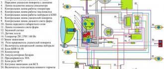
Electrical equipment IZH Planet 5
Wiring for IZH Planet 5 includes:
Video: review of IZH Planet 5 wiring
Taken by user Agronom.
Generator
IZ Planet 5 generator design:
- voltage regulator with rectifier BPV-14-10 - 1;
- rotor - 2;
- stator with windings - 3;
- current collector brushes - 4;
- ignition system cam (battery) - 5;
- ignition system contact unit - 6.
The generator converts the mechanical energy of a gasoline engine into electrical energy, which charges the battery. Alternating current is generated by 3 windings and fed to a rectifier, which converts it into direct current. An additional coil is used as an exciter.
Photo gallery: IZH Planet 5 generator and its design
Battery
To supply all components, a low-power energy storage device of 12 volts is required, since IZH Planet 5 does not have a starter. The purpose of a lead-acid battery is only to supply voltage to the ignition system and the excitation winding of the generator during startup.
Ignition system
In IZH Planet 5, the ignition coil converts low-voltage voltage into high-voltage and transmits it to the spark plug. That, in turn, is responsible for the spark that detonates the fuel. To ensure that detonation occurs only in the desired piston position, there is an ignition chopper.
From the factory, this model is equipped with a classic ignition system, which requires periodic cleaning of the breaker contacts and adjusting the gap between them.
Installing a contactless SG on a motorcycle gives:
- timely powerful sparking;
- reduction of vibration levels;
- reduction in fuel consumption.
Control devices
The following control devices are installed on the motorcycle:
- tachometer, on which there are indicator lights for the headlights and turns;
- speedometer showing total and daily mileage;
- power engine temperature indicator;
- voltmeter.
Battery
The battery in the motorcycle is low-power. The motorcycle does not have a starter, so its task is only to supply voltage to the ignition system and the generator excitation winding during starting. Thanks to the battery, designed for 12 volts, a stable start of the fifth Planet is ensured; up to the third model, the wiring was 6 volt, and the ignition was not always clear.
Possible battery malfunctions:
- - housings, plates, leakage of electrolyte.
- - determined by measurements using a hydrometer.
- - detected by measuring resistance.
- minus not on the body (frame) of the motorcycle - all the electronics will not work.
Engine characteristics
The IZH Planet-4 motorcycle is equipped with a 2-stroke engine with a cylinder size of 72 mm and a volume of 3,346 cm3. The lubrication system is separate, equipped with an oil pump that doses the flow depending on the frequency at which the crankshaft rotates and the load engine. There is an electronic type with regulation (automatic) of ignition timing depending on the frequency with which the engine crankshaft rotates. However, it does not depend on the battery. For operation, it is advisable to use gasoline with an octane rating of at least 76. The engine uses an air cooling system. Transmission from the engine to the clutch is carried out using a double-row bushing drive chain.
Wiring diagram IZH Planet 5
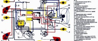
Detailed color wiring diagram for motorcycle IZH Planet 5
Explanations for the diagram
The numbers on the electrical diagram correspond to the following elements:
- Light switch, dimensions/low.
- Light switch, direction indicators and horn buttons.
- Front turn signals.
- Instrument panel lighting.
- Indicator lamp for generator operation.
- Oil pump operation indicator.
- A light indicating the operation of the neutral gear in the gearbox.
- Direction indicators.
- High beam headlight indicator.
- Front parking light bulb.
- Headlight lamp.
- Sound signal.
- Hall Sensor.
- Generator.
- Egnition lock.
- Turn signal interrupter relay.
- Neutral gear warning lamp sensor.
- Block BPV 14-10.
- Switch.
- Battery.
- Fuse.
- Relay block.
- Ignition coil.
- Foot brake light sensor.
- Rear direction indicators.
- Rear light with lamps.
Description of the symbols for the terminals on the rectifier-regulator block BPV 14-10:
- –x1 — “minus” of the generator excitation winding;
- –x2 — “minus” of the battery (“ground”);
- x2 - “positive” wire to the control lamp of the instrument panel;
- x3 - “positive” wire to the panel indicator;
- x4, x5, x7 - phases of the stator winding;
- x8 - “plus” of the battery.
Initial check sequence
An initial performance check can be performed without dismantling the generator. To do this, set the multimeter switch to the “constant voltage 20V” mode. Next, connect the black probe to the negative terminal of the battery, the red one to the positive terminal. After this, you need to start the engine and let it reach a stable idle speed. Multimeter readings ranging from 13.5 to 14.5 Volts are considered normal.
If the multimeter shows a value less than 12.8 Volts, the charging process either does not occur at all, or the charging current is extremely small. The generator is operating in abnormal mode. When the voltage is more than 14.8 Volts, the battery is overcharged. This can lead to boiling of the electrolyte, an increase in acid concentration, and destruction of the battery plates.
To check the voltage at the generator output, you need to turn on the car lamp in the open circuit from terminal 30 on the generator (the point of contact with the thick wire leading to the positive terminal of the battery or starter).
Next, connect the multimeter in the “=20V” mode with the red probe to contact 30 of the generator, and the black probe to the stripped contact on the engine or body. Start the engine. The reading on the multimeter should not be more than 15.5 volts whenever the accelerator pedal is pressed. Otherwise, further operation of the generator is dangerous for the electrical equipment of the car.
When checking, you should evaluate the degree of tension of the generator belt. Using a simplified method, this can be done by pressing on the belt with your finger.
The amount of deflection should be within 0.5 - 1 centimeter. At the same time, check the degree of belt wear. To determine the reasons for abnormal operation of the generator and perform repair work, dismantling the generator is required.
Generator
The heart is the generator (sometimes called a magneto, but they were never used on Izh Planet). Three windings produce alternating current. For excitation, an additional coil is used instead of a permanent magnet. Therefore, it is impossible to jump start a motorcycle with a completely dead or missing battery.
A diode bridge for current rectification and a voltage regulator assembled in one unit are mounted on the Izh Planet 5 generator (they are not even highlighted in the Izh Planet wiring diagram manuals).
Possible breakdowns in this unit:
- It is checked by measuring their resistance of current-carrying conductors and insulation. If the generator is damaged, it will become noticeably hot.
- — the output voltage will differ significantly from the nominal level or be absent.
- Although the electrical circuit includes short circuit protection, it happens that the automation does not work and most often the output transistor burns out.
Ignition system
The ignition chopper is used to ignite a spark at a certain point in the piston stroke. In early modifications of the electrical wiring of Izh Planet 5, contact was mounted, later electronic.
The main malfunctions of this unit:
- Burning of breaker contacts is determined visually.
- Failure of a sensor or switch elements - the easiest way to detect it is to use the method of installing a known-good unit. The lubrication system sensor valve is also checked using the same method.
- An incorrectly set ignition timing is visible from the fuzzy operation of the engine. It can be eliminated by adjustment using special probes.
The ignition coil increases the voltage to several kilovolts so that the discharge can ignite a spark at the spark plug electrodes. The secondary winding is made of a fairly thin wire; most often it burns out. Although a breakdown between the turns or onto the housing is also possible. The same troubles can (but less often) happen to the primary circuit. Everything is revealed using resistance measurements.
Maintenance
The owner can independently perform some maintenance procedures:
- check the motorcycle generator if the battery loses charge;
- set the gap between the breaker contacts;
- adjust the quality of the sound signal.
The need to inspect and adjust the wiring arises if:
- the motorcycle moves in the rain for a long time, as this causes oxidation of the contacts;
- a motorcyclist rides in an area with a lot of vegetation that damages wiring;
- The driver rides in snow in winter, which can stick to electrical wiring parts and damage them.
Self-check of the Planet 5 motorcycle generator in case of loss of charge
The cause of loss of charge in the IZH Planet 5 battery is most often a breakdown of the generator.
To check it yourself you need:
- multimeter device;
- straight screwdriver.
Step-by-step instruction
The following steps must be followed:
- Disconnect the wires from the battery and remove the generator cover.
- Disconnect the top 5 wires from the generator, first unscrewing their fastenings. In order not to mix up the wires during assembly, it is worth marking them.
- Measure the winding resistance using a multimeter in ohmmeter mode. To do this, you need to touch the body with one probe, and the other should be connected in turn to the 3 wires of the winding. There should be no short circuits, as indicated by the inscription on the multimeter screen.
- Test the resistance between the stator contacts: you need to touch them one by one with the multimeter probes. The value on the screen should be 8 ohms.
The presence of a short circuit in the 3rd stage or a discrepancy in the indicators in the 4th will indicate problems with the generator.
Photo gallery: stages of checking the IZH Planet 5 generator in case of loss of charge in pictures
How to correctly set the gap between the contacts of the breaker?
In order to set the gap between the breaker contacts, you will need:
- straight screwdriver;
- wrench 10;
- candle key;
- probe 0.4 mm thick (+/– 0.05 mm).
Next, you need to follow the steps sequentially:
- Place the motorcycle on a stand and place the gearbox in neutral.
- Remove the right crankcase cover and unscrew the spark plug.
- Using a 10mm wrench, grab the generator rotor mounting bolt and turn the crankshaft to a position where the contacts are as far apart as possible.
- Loosen the screw securing the contact.
- Place the probe between the contacts and adjust the tightening of the eccentric screw until the probe passes the contacts with little resistance.
- Tighten the contact fixing screw.
Photo gallery: adjusting the gap between the breaker contacts
Troubleshooting the audio signal and improving signal quality
Poor sound signal quality is mainly caused by improper adjustment.
The following tools will be needed for setup:
Step-by-step instruction
To adjust, do the following:
- Loosen the locknut with a wrench.
- Turn on the ignition.
- Press the button to turn on the sound signal.
- Adjust the sound by rotating the adjusting screw.
- When the desired result is achieved, tighten the locknut.
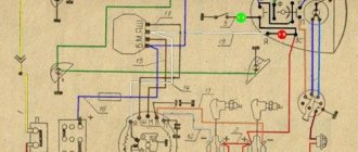
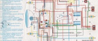
Electrical circuits of domestic motorcycles IZH Jupiter-5, Planet, IZH Junker, IZH49. To enlarge the diagram, click on it. You can also download for free and via a direct link an archive with circuit diagrams.
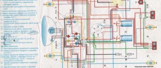
Electrical circuits of the ignition systems of the IZH Jupiter 5 motorcycle
1 - parking light lamp - A 12-4; 2 - high beam - low beam headlight - A 12-45:40; 3 - indicator lamp for generator operation - A 12-1; 4, 5 — speedometer scale illumination lamps — AMN 12-3; 6, 16, 17, 20, 23, 30 — lamps for the direction indicators of the motorcycle and side trailer; 7 - combination switch (right switch); 8 — brake light switch for the front wheel brake; 9 - breaker; 10 — spark plug; 11 — ignition coil; 12 - generator; 13 — rectifier-voltage regulator BPV14-10; 14 — brake light switch for the wheel brake; 15, 19 — side trailer clearance lamps — A 12-5; 18 — brake light lamp for side trailer — A 12-21-3; 21 — motorcycle brake light lamp — A 12-21-3; 22 — motorcycle rear marker lamp — A 12-5; 24 - battery; 25 - fuse; 26 — neutral lamp switch; 27 — ignition switch; 28 — sound signal; 29 — alarm switch (left switch); 31 — turn signal switch; 32 - high beam headlight control lamp - A 12-1; 32 — control lamp “neutral” — A 12-1; 33 - control lamp for direction indicator lights - AMN 12-3; Symbols on the BPV14-10 block (items 12,13): XI - “-” excitation windings; X2 - “-” battery (“ground”); ХЗ - “+” output to the control lamp; X4, X5, X7 - phases of the stator winding of the generator; X8 - “+” of the battery.
Improving the standard system
The ignition system can be improved in other ways. To do this, you need to identify what problems there are with the wiring. They can occur in the primary circuit between the coil and the 12V battery or due to operating conditions. A visual inspection of the primary circuit can reveal problems with connections, contacts and the ignition switch.
If operating conditions are ideal, the primary circuit will operate with a 12V battery without failure.
But when dirt and dust get into the circuit, the resistance at the contact points increases, which entails a decrease in voltage from 12 Volts to 7-8 Volts. This voltage is not enough for a powerful discharge to appear in the secondary winding of the coil. As a result, a charge of less than 12 V appears on the spark plug, which poorly ignites the combustible mixture in the cylinders. Burnt contacts, oily spark plugs and batteries with a charge of less than 12 V further worsen sparking.
Standard wiring after modification
The following measures help solve these problems:
- The plug connectors are removed and each wire is soldered using traditional soldering and then insulated.
- An additional toggle switch is installed that turns off all consumers when the engine starts. Thus, the coils are supplied with 12 volt voltage from the battery (diagram 1).
- Remake the ignition switch (IZ) (diagram 2). You need to take a wire and solder one end of it to the connector of lock 4, which is free, and the other to the positive terminal of the coil. The standard wire should be re-soldered from terminal 5 to terminal 6. After turning on this position of the key, power is supplied from the battery to the primary circuit according to a simplified scheme.
Thus, the changes made will make the electrical wiring of the IZH Jupiter 5 motorcycle more reliable and efficient.
Differences from the second Planet
For many modern citizens, the information that domestic motorcycle manufacturers worked tirelessly to improve their models in an era of total shortages may come as a surprise.
Note! The fact takes place, moreover, it is supported by official documents, in particular 1970N04P16-17 - this is the outgoing number of the factory newsletter, which described the changes made.
The new generation motorcycle received:
- Direction indicator lights are a first in domestic practice;
- Semiconductor relay for controlling direction indicators (installed in the headlight);
- New size of wheels and tires (3.50x18 versus previous - 3.25x19);
- New brand increased capacity battery (old one on IZH Planet 2 - ZMT-6);
- And, of course, more engine power. The power unit now developed 18 hp.
Modifications
But the creator engineers did not stop there and, having released the five-millionth car from the production line, presented a modification of the IZH Planet 3-01.
Among the innovations it should be noted:
- Rear passenger footrests;
- Roll bars;
- Rearview mirror;
- New steering wheel design.
For reference: The buyer paid for the changes out of his own pocket. In particular, the price for IZH Planet 3-01 was 750 rubles, the version with a stroller was 1140, and the “rural version” was even more expensive. Fortunately, care instructions were included with purchase, which made maintenance easier.
Motorcycle Features
According to industry norm, the motorcycle had an alphanumeric index:
- IZH 7.107-010 – basic model;
- IZH 7.107-020 was already equipped with a new lubrication system and improved front axle suspension. In addition, the wiring diagram of the IZH Planet 5 motorcycle had a contactless ignition system, independent of the battery;
- IZH 7.107-030 was equipped with a spring-hydraulic shock absorber and a redesigned rear wheel brake drive;
- IZH 7.107-040 was produced with modified kinematics and a modified front wheel brake. The wiring diagram on IZH Planet 5 remained contactless until 2008.
In what cases is ignition adjustment necessary?
During the operation of the vehicle, the owner faces many problems. The most serious failure is related to the engine. In order to spend significant funds on major repairs, it is necessary to monitor the technical condition of the motorcycle and carry out preventive work, including adjusting the valves and valves (video author - Hana Rulyu).
If you do not monitor the SZ, then the motorcycle engine may not reveal its full potential and will not work at full capacity. This can lead to a reduction in its service life. An ignition adjustment is necessary if the engine is running poorly, the muffler or carburetor is firing. True, before setting up the SZ, you should make sure that the cause of the malfunction is in it.
It happens that the flywheel bolt, which connects the two halves of the crankshaft, comes loose, begins to play and does not work well. Sometimes he even cuts the key.
Setting up the SZ may be necessary after repairing the ignition switch Izh Jupiter 5. The installation and connection itself are carried out according to the diagram.
SZ diagram of the IZh motorcycle
Required Parts
In order for the ignition system to work correctly, a number of auxiliary parts are required. They are listed below:
- Switch for BSZ VAZ cars. You should not choose exclusively from the low price segment. The Astro switch has a lot of positive reviews;
- Hall Sensor. The best option for Jupiter 5 is a similar manufacturer VAZ. By purchasing it in branded packaging, you protect yourself from counterfeits;
- Ignition coil with two terminals. You should choose between the gazelle engine number 406 or Oka with an electronic ignition system;
- A pair of silicone armor wires with rubber caps;
- The modulator is a butterfly-shaped plate made of iron.
Modulator
The most difficult stage is the production of the modulator. It is important to maintain the required shape. The more accurately the required dimensions are observed, the lower the likelihood of problems occurring after the system is implemented, that is, there will be no need to adjust it with a file. The ignition timing must match on any cylinder used.
The bolt hole must be located in the middle. Otherwise, the engine operation will not be synchronized. It is also recommended to check the integrity of the crankshaft bearings. If you find defects, you should immediately replace it.
The contact ignition is not able to work normally if the bearings are damaged. The thickness of the part should not exceed one and a half millimeters. If it is thin, it will not be possible to avoid deformation, and if it is thick, it will come into contact with the surface of the hall sensor housing.
To create the plate, it is allowed to use any material except steel. Aluminum and others should not be used as they are not magnetic. The drawing that must be followed can be found in the public domain. The presented diagram will be useful to those people who decide to modernize the vehicle ignition device. Below are methods for installing electrical ignition devices in Jupiter.
It must be turned by a professional turner. He will make a simple disk and draw on it the markings of elementary distances between the corners. Then, in accordance with it, you will cut out the necessary sectors at home. The cost of the modulator is seventy rubles.
It is not advisable to use an ordinary plate, since its width is less than twelve millimeters. This will not be enough to fully accumulate the energy resource in the coil. Of course, it can be installed, but achieving four thousand revolutions per minute will become impossible.
In addition to the above you will need:
- A stud with an applied thread of seven millimeters, pitch 1, as well as a pair of nuts with washers of the corresponding parameters. The priority material for these components is brass. This is explained by the least magnetization of the plate from the generator rotor. If you use a standard bolt, then difficulties may arise with the introduction of ignition. The bolt tends to follow the modulator as it is tightened. However, it is necessary to observe the leading indicator, maintain the same position of the rotor and modulator, and tighten the bolt. It is advisable to use a pin, since many are not able to perform all the necessary actions in total;
- A set of wires with connectors for ignition without contact from VAZ. This part can be purchased or made with your own hands.
Electrical equipment IZH Planet 5
The motorcycle uses 12-volt electrical equipment. The electrical wiring of the IZH Planet 5 motorcycle is single-wire, the role of the negative wire is performed by a metal frame.
Among the main components are:
- Power supplies;
- Ignition system;
- Headlight;
- Side lighting and turns.
For reference: as is customary in auto and motorcycle construction, modification of components and assemblies allows you to reduce the cost of products. For consumers, the advantage is that the price is low and a number of parts are interchangeable.
Generator
The motorcycle is equipped with a three-phase alternating current generator with an electromagnetic excitation circuit.
The principle of its operation is as follows:
- Electric current from the windings located on the stator is supplied to the rectifier;
- It converts it to direct current;
- And supplies it to consumers through the ignition switch.
The instructions provided include the following items:
- Voltage regulator with rectifier BPV-14-10;
- Generator rotor;
- Generator stator with windings;
- Current collector brushes;
- Ignition system cam (battery);
- Ignition system contact unit
For reference: on three-phase generators of the IZH Planet 5 motorcycle, the windings are connected according to a “star” or “delta” circuit. The rectifier is installed as a separate unit, and the IZH Planet 5 electrical wiring is connected to it.
Headlight
Unlike European countries, where there is a requirement that motorcycles with permanent magnet generators must be equipped with a battery - since a motorcycle with a non-working engine must have side lights - there are no such restrictions in Russia (see also about the Ural motorcycle wiring diagram).
For reference: with such a generator, IZH Planet 5 did not need an external current source when starting the engine. Therefore, the battery was not included in the electrical equipment.
The head light circuit includes:
- headlight lamp (35W);
- blue indicator lamp (2W);
- headlight parking light (4W);
- rear brake light lamp (15W).
Control devices
The following control devices are installed on the motorcycle:
- speedometer with daily and total mileage counters;
- tachometer with indicator lamps for direction indicators and headlights;
- engine temperature indicator;
- voltmeter.
Features of electrical equipment
Despite the unification of parts with other models, the IZH Yu5 wiring diagram was chosen for battery use.
We are talking about a contact ignition system, which, if the battery is dead, immediately creates problems for the owner:
- Starting the engine is difficult;
- The engine runs intermittently;
- Driving at low speeds further drains the battery.
Therefore, many owners prefer to upgrade their ignition system with their own hands to a more progressive one - a contactless electronic type. It should also be noted that repairing the wiring of IZ Jupiter 5 should there be a desire for such an upgrade (see also the article about the wiring diagram of IZ Planet 5).
For reference: unlike the Jupiter model, new wiring and an electronic ignition system were installed on the modified IZ Planet 5.
The methods proposed below are designed for simplified work - not requiring major replacement of components.
Transition to a contactless ignition system
Over the years of operation, the owners of IZH Jupiter 5 have developed more than one instruction for altering the electrical network. And almost all of them are based on elements from other domestic motorcycles (see also the features of the Ural motorcycle wiring diagram).
But there is a more progressive way in which:
- The generator and wiring remain on IZ Jupiter 5;
- Minor modifications are made to the electrical circuit;
- The battery remains for servicing auxiliary systems.
We are talking about modernizing the ignition system with the combined use of elements from the VAZ-2108 car and the Planet 5 motorcycle.
At the same time, the wiring diagram for IZ Jupiter 5 remains the same:
- Two Hall sensors are installed;
- Two electronic switches are connected to them (items 1 and 2 - from VAZ). Each sensor-commutator pair covers 1 cylinder;
- Two ignition coils from a motorcycle of the IZh family.
In the diagram above, the numbers indicate:
- Spark plug;
- Reels Planet 5;
- G8 switches;
- Hall sensors from the "eight";
- Egnition lock;
- Accumulator battery.
Modification of the generator
This technology for switching to a contactless ignition system is interesting because the motorcycle owner does not need to buy a new generator designed to work in an electronic ignition system. Accordingly, the cost of rework will be minimal.
- Make a modulator that will interrupt the circuit;
- And install it on the generator (on the rotor shaft).
A metal plate with a hole drilled in it for a mounting bolt can serve as such a modulator-chopper.
The modulator installation procedure is as follows:
- The modulator plate (in the diagram below under No. 2) is installed under the mounting bolt;
- Slightly attracted to him;
- By rotating the crankshaft, set the piston to TDC;
- We set the ignition timing;
- Tighten the plate with the mounting bolt.
For reference: in addition to the modulator, two Hall sensors are installed under the engine cover (in diagram No. 1). There are places to attach them.
Wiring Problems
Practice shows that if the motorcycle was stored in a dry garage and was not subjected to dubious alterations, then the Jupiter 5 wiring diagram lasts a very long time. From time to time you need to change some consumables, such as lamps and ignition coils, but otherwise it functions quite stably. However, this is not always the case and problems do occur, for example:
- wire breaks;
- electrical circuit short-circuit;
- failure of their individual branches of the circuit;
- weak light from incandescent lamps;
- incorrect operation of indicators;
- misfire;
- reduction in engine power;
- complete failure of the system.
The problems described above can arise both due to natural wear and tear of wiring elements, and after incompetent intervention in the circuit. There is no universal solution to the problem in this case, and in order to find out what caused the breakdown, you should be patient and have some basic knowledge of the technical part of the motorcycle. First of all, you should get a multimeter or assemble a primitive network indicator using a 12-volt light bulb to “ring” the wiring for breaks. Having found a circuit node that is not working correctly or a wiring break, it will need to be eliminated, the network’s functionality re-checked, and so on, until operation is completely restored.
Tuning the Izh motorcycle. BSZ on Izh Jupiter
The main problem with the Izh Jupiter motorcycle engine is the standard contact ignition system. Any owner of Jupiter sooner or later faces the problem of failure of one of the cylinders due to a change in the gap in the contacts or failure of the capacitor. Adjustment helps, but usually not for long. This problem can be radically solved by installing a contactless ignition system on a motorcycle.
Single-channel BSZ.
There are probably many options for BSZ design, but we won’t consider them all. Let's focus on the simplest, and probably the most common option in our country. There is no motorcycle market or motorcycle store nearby where you can buy a factory-made BSZ, and there is no turner with a machine nearby either. We will proceed from this.
Minimum set for installation
But we can’t do without a minimum set, so before you start work, you need to stock up on the following components, which are sold in any auto shop or car market in our country:
1. Switch from VAZ 2108
2. Hall sensor from VAZ 2108
3. Set of wires for BSZ from VAZ 2107 (from distributor (Hall sensor) to switch)
4. Two-terminal ignition coil (from an Oka or Gazelle car with a ZMZ 406 engine)
5. Two automotive silicone high-voltage wires of the required length with caps for spark plugs (you can buy a kit for a VAZ and take it from there, you can simply find used wires, after first making sure they are working)
Next, in addition to the components, we will need a small flat piece of sheet steel 1-1.2 mm thick to make a modulator and a plate for the Hall sensor. I warn you right away that stainless steel or non-ferrous metals are not suitable for the manufacture of the modulator, since they are not magnetic materials. To make a plate for the Hall sensor, you can use any material of sufficient strength.
Tools you may need are a drill with drills, files, a chisel, a hammer and other tools that, as a rule, are found in any garage.
Rework process
We dismantle the old ignition system. We remove the plate with contacts, capacitors, ignition coils with high-voltage wires from the motorcycle. We install the switch in the right glove compartment.
We attach the ignition coil to the frame under the tank. We connect the wiring connector to the switch, connect the black ground wire from the connector to ground. We connect the wire from terminal No. 1 of the switch connector to one of the coil terminals. We connect the second terminal of the coil to the old wiring, to the wire to which “+12V” is supplied when the ignition is turned on. In the old wiring, this wire connected both ignition coils. From it we pull an additional “+12V” wire to the switch, which we connect to the 4th wire in the connector. We carefully isolate everything. We insert the wire with the connector to the Hall sensor into the cavity of the generator.
You can check the functionality of the system. We connect the Hall sensor to its connector, connect the high-voltage wires to the coil and to the spark plugs. We provide reliable weight to the candles. Turn on the ignition and pass a metal object (you can use a flat screwdriver) through the Hall sensor slot. The spark plugs should spark. The scheme is working. (If there is no spark, then something is connected incorrectly and everything needs to be checked again.) Now it remains to supply a spark at the right time to the cylinders, for this:
We make a plate for mounting the Hall sensor.
There are no requirements for the shape of the plate as such. It must ensure that the Hall sensor is mounted at a certain distance from the armature axis.
The approximate markings of the central hole and cutouts for the mounting screws to the generator can be copied from the old, removed contact mounting plate. We mark the Hall sensor mount in such a way that the distance to the rear wall of the sensor through the magnet slot from the center of the armature is around 60-65 mm. You can machine additional grooves in the plate being manufactured in the attachment to the generator to ensure slight rotation of the plate around its axis (to facilitate setting the ignition timing), but you don’t have to do this, but simply attach the plate tightly to the generator. We drill, sharpen, adjust in place, install the plate with the Hall sensor on the generator.