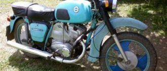
In 1970, the IZH Planet 3 model appeared in the production program of the Izhevsk Motor Plant.
Unlike its predecessor with the index “2,” the motorcycle received a new shaped gas tank, a more powerful engine and direction indicators.
Unification of the electrical circuit with other models is a traditional way to reduce costs
Motorcycle Features
The electrical wiring of IZH Planet 3 was designed for 6 volts. It served as the basis for other motorcycle models produced later (see also wiring diagram for IZH Planet 5).
Among the features are:
- Generator G36M7, which was later modified;
- Voltage regulator relay RR-1;
- Ignition coil IZH 56;
- Turn signal relay PC419.
For reference: The installation of markers and turn signals was used for the first time on domestic motorcycles. In general, for its progressive design and high quality, the IZH Planet 3 model received the state quality mark, which can be seen in the video of previous years.
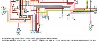
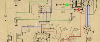
Original and color wiring diagram for IZH Planet 3
4 years after the appearance of the second Planet (1966), the factory workers made a number of changes to its design, designed to improve the technical parameters and appearance of the motorcycle. This is how IZ Planet 3 was born, which became a real symbol of freedom for many of our compatriots.
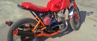
Despite its advanced age, IZH Planet 3 still serves its owners well
Converting the electrical circuit to work without a battery
Unlike cars that have a closed engine and electrical wiring, parts of the IZH Planet 3 motorcycle are more susceptible to external factors than others:
- Rain and snow;
- Direct sunlight;
- Mechanical damage from bushes.
The owners are especially troubled by the standard battery, which is also quite difficult to maintain (see also the Ural motorcycle wiring diagram).
The factory instructions provide:
- The need to constantly check the electrolyte level in banks, because when the motorcycle tilts, it inevitably leaks out;
- The need to constantly check the electrolyte density. This forces motorcycle owners to have a hydrometer, distilled water and hydrochloric acid on hand to restore the required density with their own hands.
Differences from the second Planet
For many modern citizens, the information that domestic motorcycle manufacturers worked tirelessly to improve their models in an era of total shortages may come as a surprise.
Note! The fact takes place, moreover, it is supported by official documents, in particular 1970N04P16-17 - this is the outgoing number of the factory newsletter, which described the changes made.
In the photo - official materials of the Izhmash Design Bureau
The new generation motorcycle received:
- Direction indicator lights are a first in domestic practice;
- Semiconductor relay for controlling direction indicators (installed in the headlight);
- New size of wheels and tires (3.50x18 versus previous - 3.25x19);
- New brand increased capacity battery (old one on IZH Planet 2 - ZMT-6);
- And, of course, more engine power. The power unit now developed 18 hp.
Modifications
But the creator engineers did not stop there and, having released the five-millionth car from the production line, presented a modification of the IZH Planet 3-01.
Mirror and safety arches are the distinctive features of the new modification
Among the innovations it should be noted:
- Rear passenger footrests;
- Roll bars;
- Rearview mirror;
- New steering wheel design.
For reference: The buyer paid for the changes out of his own pocket. In particular, the price for IZH Planet 3-01 was 750 rubles, the version with a stroller was 1140, and the “rural version” was even more expensive. Fortunately, care instructions were included with purchase, which made maintenance easier.
Stages of electrical equipment modification
The entire procedure for switching to a battery-free circuit comes down to:
- Replacement of components for 12 volt equipment;
- Remaking the generator, and sometimes borrowing it from another model;
- Replacing lamps from 6V to 12V.
For reference: the wiring diagram on IZH Planet 3 does not change significantly - only the circuits of the generator, coil and voltage regulator relay are replaced.
Generator
The main difficulty in altering the generator lies in the manufacture of a special intermediate ring. This requires the help of a turner - the ring is turned on a lathe.
Photo of the drawing of the intermediate ring for the generator
Also in the ring:
- Two 6 mm holes are drilled to allow the ring to be secured on the right half of the crankcase;
- To attach the generator to the ring, three M5s are drilled;
- A segment is cut out of the ring to facilitate installation under the partition of the right half of the crankcase;
- Cutouts for the crankcase cover bosses are made on the right and bottom.
Diagram of the modified generator
The numbers on the diagram indicate:
- Carter - right half;
- Power unit crankshaft;
- Intermediate flange mounting screws;
- The intermediate flange itself;
- Conical bushing made of sheet metal (S 0.8 mm);
- Generator stator;
- M5 screws for mounting the generator;
- Generator rotor;
- Rotation sensor;
- Rotor mounting bolt.
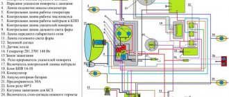
Electrical diagram
When converted to work without a battery, the wiring diagram of the IZH Planet 3 motorcycle remains standard:
- Wires to electricity consumers (dimensions, brake lights, head lights and instruments) remain unchanged;
- The standard ignition coil is replaced with another one - type B300B;
- The KET-1 electronic switch can be placed in a tool box, which helps protect it from external factors.
Advice: motorcyclists who have done this modification note the undoubted advantages of switching to contactless ignition. The wiring of IZH Planet 3 remains almost unchanged, but there is a complete refusal to use the battery. And the cost of reconstruction is small.
Conclusions: the proposed conversion method has been tested on thousands of motorcycles of domestic owners (see also the IZ Jupiter 5 wiring diagram). And it has proven its worth with trouble-free operation, improved spark generation and reliable engine starting in harsh winter conditions.
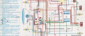
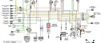
Electrical diagram of IZH PLANET
The diagram on the Izh Planet completely coincides with the Izh 56 motorcycle. However, the electrics of this motorcycle are a separate story.
Amazing but true: all electrical parts were used on subsequent motorcycle models without any changes! That is, by and large, the electrical circuit of the Izh Planet was basically the same as the subsequent models of the series. Perhaps “double” ignition on Jupiters. And I can't say anything bad about the electrics on these bikes. Archaic now, the 6-volt electrical system was standard back then. The DC generator, contact relay-regulator and battery worked quite reliably together. Moreover, if the battery had to be recharged, and the brushes of the generator had to be changed and the commutator cleaned, then the relay-regulator worked flawlessly. And it still works on a lot of motorcycles. The reliability of the generator is amazing - they still work! Compare with the long-dead magnets of the Voskhod generators. There is no need to talk about the quality of lighting - the battery system made it possible to obtain an even light from the headlights, regardless of engine speed. For example, on 6-volt emkas there is nothing like light! However, the power of the 45-watt generator was only enough for this motorcycle. Its use on Jupiters with their increased electricity consumption for ignition was not entirely successful. 1 — brake light switch; 2 — brake light lamp A6-15; 3 — rear position lamps A6-6 (3a — on the stroller); 4 — battery 3MT-6; 5 — light switch with sound signal button P25 or P200; 6 — sound signal C37; 7 — neutral control lamp switch; 8 — ignition coils IZH-56 sb. 39 (on IZH-56 and IZH-Planet - one); 9 - fuse 15A; 10 — relay-regulator; 11 — generator G-36M-1 or G-36M-2; 12 — speedometer scale illumination lamp A6-1; 13 — neutral control lamp A6-32+21; 15 — front side light lamp A6-4; 16 - central switch; 17 — control lamp for generator operation A6-0.25.
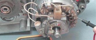
Setting up the Izh Planet ignition:
1. Place the motorcycle on the center stand or side stand and engage neutral gear.
2. Remove the right crankcase cover (see photo).
3. Turn out the spark plug.
4. Turn the crankshaft to the position of the maximum open contacts (to do this, you can “grasp” the head of the generator rotor mounting bolt with a 12 mm wrench).
5. Use a screwdriver to slightly loosen the contact fastening screw.
6. Place a probe 0.35-0.45 mm thick between the contacts and, turning the adjusting eccentric screw with a screwdriver, achieve a position in which the probe plate slides along the contacts with some force.
Source
How to improve the standard electrical system?
As we have already said, standard wiring does not cause any particular complaints due to its solidity, ability to withstand oxides and rust at the joints, without losing functionality. That is why complete replacement of wiring is a questionable procedure, but upgrading individual parts makes sense. By individual parts, we mean such functional elements as head lights, indicators, turn and stop lamps, ignition system, generator. Let's talk about each of the elements separately.
Dashboard
The new instrument panel fits well into the appearance of the new motorcycle model, combining:
- Speedometer;
- Automotive type ignition switch;
- Control and warning lamps.
The display of warning lamps separately from the instrument scales had a positive effect on the information content. Now the driver can easily see their readings, additionally provided with inscriptions.
It is also easy to replace burnt out lamps:
- Using a Phillips screwdriver;
- Remove 3 screws (in the diagram above under No. 3);
- Remove the cover;
- Remove the failed lamp;
- Install working;
- Reassemble the shield in reverse order.
Required Parts
In order for the ignition system to work correctly, a number of auxiliary parts are required. They are listed below:
- Switch for BSZ VAZ cars. You should not choose exclusively from the low price segment. The Astro switch has a lot of positive reviews;
- Hall Sensor. The best option for Jupiter 5 is a similar manufacturer VAZ. By purchasing it in branded packaging, you protect yourself from counterfeits;
- Ignition coil with two terminals. You should choose between the gazelle engine number 406 or Oka with an electronic ignition system;
- A pair of silicone armor wires with rubber caps;
- The modulator is a butterfly-shaped plate made of iron.
Modulator
The most difficult stage is the production of the modulator
It is important to maintain the required shape. The more reliably the required dimensions are observed, the lower the likelihood of problems occurring after implementing the system, that is, there will be no need to adjust it using a file
The ignition timing must match on any cylinder used.
The bolt hole must be located in the middle. Otherwise, the engine operation will not be synchronized. It is also recommended to check the integrity of the crankshaft bearings. If you find defects, you should immediately replace it.
The contact ignition is not able to work normally if the bearings are damaged. The thickness of the part should not exceed one and a half millimeters. If it is thin, it will not be possible to avoid deformation, and if it is thick, it will come into contact with the surface of the hall sensor housing.
To create the plate, it is allowed to use any material except steel. Aluminum and others should not be used as they are not magnetic. The drawing that must be followed can be found in the public domain. The presented diagram will be useful to those people who decide to modernize the vehicle ignition device. Below are methods for installing electrical ignition devices in Jupiter. It must be turned by a professional turner. He will make a simple disk and draw on it the markings of elementary distances between the corners. Then, in accordance with it, you will cut out the necessary sectors at home. The cost of the modulator is seventy rubles.
It is not advisable to use an ordinary plate, since its width is less than twelve millimeters. This will not be enough to fully accumulate the energy resource in the coil. Of course, it can be installed, but achieving four thousand revolutions per minute will become impossible.
In addition to the above you will need:
- A stud with an applied thread of seven millimeters, pitch 1, as well as a pair of nuts with washers of the corresponding parameters. The priority material for these components is brass. This is explained by the least magnetization of the plate from the generator rotor. If you use a standard bolt, then difficulties may arise with the implementation of the ignition. The bolt tends to follow the modulator as it is tightened. However, it is necessary to observe the leading indicator, maintain the same position of the rotor and modulator, and tighten the bolt. It is advisable to use a pin, since many are not able to perform all the necessary actions in total;
- A set of wires with connectors for ignition without contact from VAZ. This part can be purchased or made with your own hands.
Installation of BSZ
Contactless ignition system - this element has become so popular that it rightfully occupies the place of the most popular improvement to the standard ignition circuit. From the factory, the IZ Jupiter 5 wiring model is equipped with a contact ignition system. It is unable to hold the ignition angle advance settings for a long time, has failures in operation and low accuracy. The disadvantages of this system can be listed for a very long time, so owners switch to electronic ignition, thereby increasing power, reducing consumption and getting a flat torque and power curve.
Setting up contact ignition on Izh Jupiter - 5
Let's take a step-by-step look at how to set up contact ignition on this device:
- Align the piston of the desired cylinder: - insert a screwdriver into the cylinder - rotate the crankshaft while holding the screwdriver
- Take a ruler and place it next to the screwdriver.
- Rotate the crankshaft, holding the screwdriver down with your finger so that it is level. We find a dead point.
- Turn the crankshaft in the opposite direction (1.5-2 mm).
- A spark is generated when the cam opens, locate the two adjusting bolts.
- Take a light bulb with two contacts, connect one to ground, the other to the contact.
- Turn on the ignition switch.
- You need to find the moment when the light comes on (the moment it lights up, the start occurs), and when it goes out, the contact closes on the contrary.
- Turn off the ignition, do and adjust the same with the second cylinder
conclusions
We hope that the proposed algorithm for refining the standard electrical system of the IZH Jupiter 3 motorcycle with video and photo materials will help you (see also). And you will use this method to upgrade your own motorcycle.
The charger disappeared somewhere and suddenly reappeared, it suddenly stalled during the journey or some mode does not work and the tidy is acting up - a common problem that needs to be solved. After many years of use, when you start to figure out what goes where and where, the roof goes askew, there are some twists, kilometers of electrical tape, oh yeah, things won’t work that way! I’ll say right away that I work at a car disassembly shop, getting wires or spare parts is not a problem, so, it’s decided and done - the wiring is made of Japanese wires and Chinese heat shrink. I spent a day on this. I didn’t buy connectors, I just opened them, took the wire of the required length, inserted it, clamped it, sealed it, put on a heat-shrink tube - hair dryer and voila! the wiring is ready :) then the whole harness is braided, we look and rejoice.
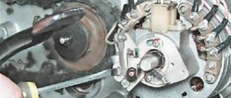
I decided to put up a horseshoe because I wanted to and that’s it! Is there too much room under the saddle for me? For supertuning, we will need a horseshoe from a vase (about 270 rubles), a relay-regulator (about 150 rubles), it’s better to buy it in a good store, make two brackets ourselves [-shaped (not visible in the photo, the relay is attached to them), an angle grinder. We “finalize” the relay regulator - we cut off a little meat (in the picture on the top left where the output contact is), we bend the contact itself inward, we also make two mounting holes, you can dig it out by hand with a 3 mm drill Using a grinder, we cut off the excess on the generator so that the diode bridge is without problems got in there. Everything is done locally and to the best of your imagination (we file the diode bridge so that the clutch cover does not touch it!). We secure the horseshoe with bolts - so that the diodes do not touch the ground, I used textolite washers. Yes, it’s not very beautiful, but it’s compact and has been working for the second season! Don’t forget, aluminum doesn’t solder well, so it’s better to make a hole, screw on a small bolt and nut and solder the positive wire to it!
In this picture everything is chewed in detail
BSZ! every homeowner's dream! I won’t describe the entire process of purchasing and components; there is plenty of information on the Internet. Like everyone else, I first decided to install a hall sensor (HH), I drove it for a ride, it works, but progress does not stand still! I found a replacement - the BS5-2M optical sensor! It costs quite a lot - about 250 rubles. The VAZ switch receives its signal without any problems. beautiful, but expensive, and if an arctic fox fails somewhere, it’s better to carry a spare one with you (if you still install BS5, I advise you to solder the body and side of the contacts carefully with a soldering iron, otherwise it may die from vibration) And finally, a few photos
We would like to note right away that motorcycles of the IZH family were the most democratic and affordable form of transport in the 80s, which gave freedom of movement to many young men and adult men. In those years there was no Internet and cable TV, so wiping your pants on the couch was unfashionable
. But the wiring diagram for the IZH Jupiter 3 was read to the gills by these same young men, which many adult aunts and uncles recall with nostalgia today.