Electrical equipment IZH Planet 5
Wiring for IZH Planet 5 includes:
- generator;
- battery;
- ignition system;
- headlights;
- control devices;
- switching elements.
Video: review of IZH Planet 5 wiring
Taken by user Agronom.
Generator
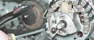
IZ Planet 5 generator design:
- voltage regulator with rectifier BPV-14-10 - 1;
- rotor - 2;
- stator with windings - 3;
- current collector brushes - 4;
- ignition system cam (battery) - 5;
- ignition system contact unit - 6.
The generator converts the mechanical energy of a gasoline engine into electrical energy, which charges the battery. Alternating current is generated by 3 windings and fed to a rectifier, which converts it into direct current. An additional coil is used as an exciter.
Photo gallery: IZH Planet 5 generator and its design
Battery
To supply all components, a low-power energy storage device of 12 volts is required, since IZH Planet 5 does not have a starter. The purpose of a lead-acid battery is only to supply voltage to the ignition system and the excitation winding of the generator during startup.
Ignition system
In IZH Planet 5, the ignition coil converts low-voltage voltage into high-voltage and transmits it to the spark plug. That, in turn, is responsible for the spark that detonates the fuel. To ensure that detonation occurs only in the desired piston position, there is an ignition chopper.
From the factory, this model is equipped with a classic ignition system, which requires periodic cleaning of the breaker contacts and adjusting the gap between them.
Installing a contactless SG on a motorcycle gives:
- timely powerful sparking;
- reduction of vibration levels;
- reduction in fuel consumption.
Control devices
The following control devices are installed on the motorcycle:
- tachometer, on which there are indicator lights for the headlights and turns;
- speedometer showing total and daily mileage;
- power engine temperature indicator;
- voltmeter.
Headlight and dashboard lamps
Conventional incandescent lamps are installed as lighting equipment and to illuminate the dashboard. Switching elements are responsible for supplying electricity from the battery to the lamps.
The headlight circuit includes lamps:
- headlight (35 watt);
- parking light headlights (4 W);
- control - blue light (2 watts);
- rear brake light (15 W).
Switching elements
Switching elements are various types of switches that close or open an electrical circuit. They can be activated using keys on the dashboard (for example, turn signals) or by sensors.
In IZH Planet 5, the switching elements include:
- turn switches;
- signal key;
- switches for low/high beam headlights;
- neutral sensor;
- egnition lock;
- foot and hand brake sensors.
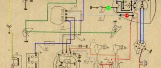
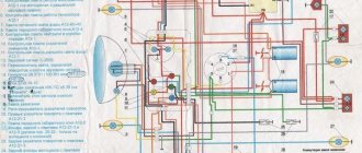
Wiring diagram IZH Planet 5
Detailed color wiring diagram for motorcycle IZH Planet 5
Explanations for the diagram
The numbers on the electrical diagram correspond to the following elements:
- Light switch, dimensions/low.
- Light switch, direction indicators and horn buttons.
- Front turn signals.
- Instrument panel lighting.
- Indicator lamp for generator operation.
- Oil pump operation indicator.
- A light indicating the operation of the neutral gear in the gearbox.
- Direction indicators.
- High beam headlight indicator.
- Front parking light bulb.
- Headlight lamp.
- Sound signal.
- Hall Sensor.
- Generator.
- Egnition lock.
- Turn signal interrupter relay.
- Neutral gear warning lamp sensor.
- Block BPV 14-10.
- Switch.
- Battery.
- Fuse.
- Relay block.
- Ignition coil.
- Foot brake light sensor.
- Rear direction indicators.
- Rear light with lamps.
Description of the symbols for the terminals on the rectifier-regulator block BPV 14-10:
- –x1 — “minus” of the generator excitation winding;
- –x2 — “minus” of the battery (“ground”);
- x2 - “positive” wire to the control lamp of the instrument panel;
- x3 - “positive” wire to the panel indicator;
- x4, x5, x7 - phases of the stator winding;
- x8 - “plus” of the battery.
Switching elements.
These include switches (high-low, turns, engine stop, etc.) as well as brake and neutral sensors and the ignition switch. You can easily “ring” them with a tester, finding out which contact group is not working.
Switching also includes the Izh electronic turn signal relay. Its malfunction is visible by the absence of interruption or no voltage supply to the turn signals.
As can be seen from all of the above, the wiring on Izh Planet is without any special secrets or complex elements, all its parts are easily diagnosed and repairs should not cause difficulties.
Now we advise you to watch the video, which shows in detail and clearly the assembly of the Izh Planet 5 circuit.
The road version of the IZH Planet 5 motorcycle differed favorably from other domestic analogues by the use of an oil pump, which made it possible to abandon the scheme for pre-mixing fuel with oil.
In addition, subsequent modifications were distinguished by their contactless ignition system, independent of the battery, and modified kinematics.
This allowed:
- To set the motorcycle in motion “from the pusher” - by turning on the ignition, the owner engaged second gear and, using his own efforts, pushing the motorcycle forward, started the engine;
- Operation without a battery was possible during daylight hours (a battery was still required for the side lights and headlights to operate).
According to industry norm, the motorcycle had an alphanumeric index:
- IZH 7.107-010 – basic model;
- IZH 7.107-020 was already equipped with a new lubrication system and improved front axle suspension. In addition, the wiring diagram of the IZH Planet 5 motorcycle had a contactless ignition system, independent of the battery;
- IZH 7.107-030 was equipped with a spring-hydraulic shock absorber and a redesigned rear wheel brake drive;
- IZH 7.107-040 was produced with modified kinematics and a modified front wheel brake. The wiring diagram on IZH Planet 5 remained contactless until 2008.
In addition, a side trailer (sidecar) or a universal cargo platform (without a seat) could be attached to the motorcycle.
Maintenance
The owner can independently perform some maintenance procedures:
- check the motorcycle generator if the battery loses charge;
- set the gap between the breaker contacts;
- adjust the quality of the sound signal.
The need to inspect and adjust the wiring arises if:
- the motorcycle moves in the rain for a long time, as this causes oxidation of the contacts;
- a motorcyclist rides in an area with a lot of vegetation that damages wiring;
- The driver rides in snow in winter, which can stick to electrical wiring parts and damage them.
Self-check of the Planet 5 motorcycle generator in case of loss of charge
The cause of loss of charge in the IZH Planet 5 battery is most often a breakdown of the generator.
Engine disassembly
Repairing the IZH Planet engine can be done entirely with your own hands, since the simple design allows this. The main postulate of such work is to follow the established order of disassembly and assembly. Following the diagram below, you can get to all engine elements in order to inspect or replace them. It makes sense to completely disassemble the engine if you need to get to the crankshaft or left oil seal. Failure of the latter leads to a decrease in driving characteristics and smoking due to the presence of a large amount of oil inside the crank chamber.
Step-by-step disassembly diagram:
- Unscrew the spark plug and nuts from the top of the cylinder. We remove the cylinder with the piston.
- We drain the remaining oil in the engine and remove the engine from the frame (mounts in the front and rear), having first disconnected and numbered all the wires.
- We unscrew the left cover and remove as much as possible the gearbox and other accessible elements.
- From under the right cover we remove the generator, the final drive sprocket and the crankshaft oil seal.
- We remove all accessible parts related to the gearbox.
- On the right we find the screws that tighten the crankcase parts. We unscrew them together with the nuts of the two bolts.
- Use a rod of suitable diameter to push out the installation sleeves so that they partially remain in the grooves.
- Using a mallet, lightly tap along the entire plane of contact between the crankcase parts. If the parts do not move away from each other or come off partially, try inserting a mounting blade into the groove and tapping it without much force.
Important! Using excessive force or picking at the crankcase halves with sharp objects is prohibited! Otherwise, the fragile aluminum may be damaged.
- Unscrew the locking plate and remove it.
- We take out the ring-washers, simultaneously noting their order.
- The left side of the crankcase can now be removed from the crankshaft. If the element does not give in, you can use light blows with a rubber hammer to help the parts separate.
- Using pliers, remove the retaining ring. To remove ball bearings, you will need a pipe or similar element, the end of which coincides with the outer race of the bearing. We lean it against the bearing and little by little knock it out of its mounting position.
- By lightly tapping, remove the guides of the gear shift units.
- We take out the retaining ring installed inside, and behind it the split remote ring.
- Press in the left oil seal. Similarly, we take out the main bearing ring installed on the right.
Engine disassembly is complete, now you can repair the IZH Planet 5 engine.
Remember! If you are carrying out this procedure for the first time, then organize your workplace and carefully put all the removed parts, writing down the most difficult disassembly moments for you.
Current wiring diagram of IZH Planet 5 and its problems
There is no need to have special stands and equipment for repairs. A minimum knowledge of electrical engineering and a simple avometer (tester) is enough; even often you can get by with just a test lamp.
We will tell you in more detail about the main electrical wiring components and possible malfunctions. The Izh Planet wiring diagram makes it easy to find a broken wire or damaged insulation (for example, a bad contact always gets hot).
But pay special attention to the fact that the electrical circuit is designed not only for 12 volts, there is also a high-voltage cable (connecting the coil and the spark plug), which cannot be checked with a regular ohmmeter.
In this case, we look to see if there is a spark at the coil output and at the output at the spark plug contact. Let's take a closer look at the main wiring components of the Izh Planet.
Electrical equipment of motorcycles IZH 7.107-01
The electrical diagram is given in Appendix 6. The electrical equipment of the motorcycle includes:
- sources of electricity - battery and generator;
control device - rectifier-voltage regulator;
ignition devices - ignition coil, sensor, switch and spark plug;
lighting and signaling devices - headlight, tail light, direction indicator lights, sound signal (for a motorcycle with a side trailer, additional front marker light and rear light);
control and monitoring devices - ignition switch, warning lamps, turn signal switch, lighting mode switch, horn switch, turn signal switch, lighting mode switch, high beam alarm switch, emergency engine switch, brake light switch front and rear wheel brakes.
5.4.1. Motorcycle generator IZH 7.107-01
The generator (Fig. 30) is single-phase alternating current with excitation from permanent magnets.
The generator rotor is installed on the cone of the right semi-axis of the engine crankshaft, the stator is installed in the generator cover or on a base fixed to the engine crankcase. The stator has two separate windings: charging and power. The charging winding is connected directly to the switch and serves to power the engine ignition system; the power winding, through a rectifier-regulator, provides power to lighting devices, an alarm system and charging the battery.
Rice. 30. Generator and ignition sensor:
1 - rotor; 2 - stator; 3 - ignition sensor
The ignition system is powered by alternating current; other consumers are powered by a rectifier-voltage regulator by direct current.
The generator does not have sliding contacts or rubbing parts; its maintenance is reduced to monitoring the condition of electrical insulation, wire connections and the reliability of fastening of the rotor and stator.
The serviceability of the generator set (generator-rectifier - voltage regulator) is checked using a DC voltmeter with a scale division of 0.1 V. The voltmeter is connected to the “+” terminal of the rectifier-voltage regulator and to ground. At medium engine speeds with the battery connected and the headlights on high beam, the voltage should be 13.7...14.7 V. A deviation of the voltage from the specified values indicates a malfunction of the rectifier-voltage regulator or generator.
Remove the generator from the engine in the following order:
- disconnect the wires of the generator and ignition sensor from the rectifier-voltage regulator, switch, main harness;
remove the generator cover with the stator, remove the four screws securing the stator and the screw of the bracket securing the wires to the generator cover, disconnect the stator from the generator cover;
Unscrew the rotor mounting bolt, using the screw from the device for squeezing out the chain link axis as a puller (screw it into the rotor shaft), remove the rotor.
If the stator is installed on a base fixed to the crankcase, unscrew the four screws securing the stator to the base and remove the stator with the harness.
Install the generator in reverse order.
5.4.2. Motorcycle battery IZH 7.107-01
The battery is the power source when the engine is not running. The “-” terminal of the battery is connected to the “ground” of the motorcycle. Reverse connection of the terminals is unacceptable, as it leads to failure of electronic devices, other electrical equipment components and the battery itself.
The activation, operation and maintenance of the battery are described in the attached operating instructions for the battery.
A capacitor with a capacity of 2200 microfarads is connected in parallel to the battery, designed to smooth out the ripples of the rectified voltage and ensure normal operation of the motorcycle's electrical energy consumers when the battery fails or is missing.
5.4.3. Rectifier-voltage regulator for motorcycles IZH 7.107-01
The rectifier-voltage regulator (Fig. 31) or voltage regulator is designed to rectify the alternating current of the generator, maintain the voltage of the generator within specified limits and ensure reliable operation of the entire electrical equipment system, the connection of which to the system is different (see electrical diagram in the appendix 7).
Rice. 31. Diagram of the rectifier-voltage regulator BPV 21-15
To avoid disruption of the thermal operating conditions of the rectifier-regulator, it is necessary to periodically (at least once every six months) clean it with a brush from dust and other contaminants. It is not allowed to clean with metal objects or break the factory seal during the warranty period of the motorcycle.
5.4.4. Ignition installation for motorcycles IZH 7.107-01
The initial ignition timing angle is determined by the relative position of the ignition sensor and the generator rotor and is not subject to adjustment during operation. When the engine is running, the ignition system automatically changes the ignition timing depending on the crankshaft speed.
5.4.5. Electronic switch for motorcycles IZH 7.107-01
The electronic switch is designed to accumulate the energy produced by the generator and transfer it to the ignition coil.
The switch is housed in a hermetically sealed plastic case, which prevents moisture from entering. It requires no maintenance and cannot be repaired.
5.4.6. Motorcycle ignition sensor IZH 7.107-01
The ignition sensor (Fig. 30) is designed to create a control pulse for the ignition switch. During operation it does not require maintenance and cannot be repaired.
5.4.7. Motorcycle ignition coil IZH 7.107-01
The ignition coil (Fig. 32) is designed to convert the energy accumulated in the commutator into a high-voltage pulse supplied to the spark plug. During operation, it is necessary to clean the coil from dust and other contaminants.
Cannot be repaired.
Rice. 32. Ignition coil
5.4.8. Spark plug for motorcycles IZH 7.107-01
After 2500-3500 km, check the condition of the spark plug; if carbon deposits form and become oily, rinse the spark plug in clean gasoline and dry it.
Check the gap between the spark plug electrodes with a feeler gauge. When adjusting the gap, carefully bend the side electrode. Install the spark plug into the socket with a sealing ring.
5.4.9. Spark plug tip for motorcycles IZH 7.107-01
The spark plug tip (Fig. 33) connects the spark plug to the high-voltage wire of the ignition coil and ensures that radio interference is reduced to acceptable standards. During operation, it is recommended to periodically check the reliability of the fastening of the wires in the tip and in the ignition coil, blow through the tip to remove dust between the screen and the body, and wipe the tip inside. The wire must be screwed into the lug until it stops.
Rice. 33. Candle tip:
1 - body; 2 - resistor; 3 - wire; 4 - screen
5.4.10. Motorcycle headlight IZH 7.107-01
The headlight has two lamps: a main light with two filaments (low and high beam) and a parking light. To better utilize the light quality and reduce glare, the headlight must be adjusted. Before adjustment, place the motorcycle on a horizontal platform perpendicular to the Screen at a distance of 10 m. The load on the motorcycle during adjustment is the driver. The adjustment should be made with the low beam on in accordance with the screen markings (Fig. 34), while the longitudinal vertical plane of symmetry of the motorcycle should intersect with the screen along line AB.
Rice. 34. Headlight adjustment
5.4.11. Brake light switches for motorcycles IZH 7.107-01
The brake light switches for the front and rear wheels are used to turn on the light signal when the motorcycle is braking. Adjust the moment when the signal is turned on in the event of a change in the position of the rear wheel brake lever by moving switch 1 (Fig. 35) with its fastening loosened. The brake light must come on before the wheel begins to brake.
The front wheel brake light switch is installed in the front wheel brake lever bracket and does not require adjustment.
Rice. 35. Adjusting the brake light switch:
1 — brake light switch; 2 - screw; 3 - nut; 4 - spring; 5 - traction
5.4.12. Motorcycle sound signal IZH 7.107-01
The sound signal does not require maintenance. The sound strength can be adjusted using an adjusting screw located on the body.
5.4.13. Motorcycle fuse IZH 7.107-01
The fuse consists of body 1 (Fig. 36), cover 3 and fuse link 2 for 10 A.
The fuse is connected to the “+” terminal of the rectifier-voltage regulator.
If the fuse link burns out, eliminate the cause that caused the combustion and replace it by disconnecting the body from the lid.
Monitor the condition of the contact connections of the fuse, cleaning them from contamination.
Rice. 36. Fuse:
1 - body; 2 — fuse-link; 3 - cover
5.4.14. Turn signal switch
The direction indicator breaker IZHRP-4 (Fig. 37) is designed to interrupt the power supply circuit of the direction indicator signal lamps and monitor the serviceability of these lamps.
The turn signal switch is located on the frame under the gas tank. It is protected against short circuits in the signal lamp circuit and does not require maintenance. Cannot be repaired.
Rice. 37. Electrical circuit diagram of the direction indicator switch IZH RP.4:
“+” - positive output; “-” — negative output (“mass”); N - load terminal
Motorcycle IZH Planet 4 rectifier-regulator
voltage, the main role of which is to rectify the current, charge the battery and power all electrical devices of the motorcycle from a 100W alternator. The rectifier-regulator changes alternating current into direct current and makes it more stable. Which has a positive effect on the lighting, the operation of the turn signal and brake light breaker. The serviceability of the rectifier-voltage regulator and at the same time the serviceability of the generator on IZH motorcycles is checked using a test lamp. When the engine is switched off, the indicator lights up, and when the engine is running, it goes out. This indicates that the generator and rectifier-regulator are working properly.
Caring for the rectifier-regulator involves cleaning it from dust and dirt. Dirt slows down the cooling of the rectifier-regulator, which leads to its failure.
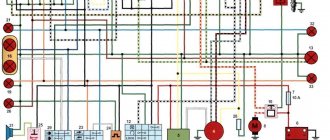
For the correct connection of the rectifier-voltage regulator on the Izh Planet 4 motorcycle, the following photo shows what color the wire is and where it is connected on the connecting block. Symbols of terminals on the rectifier-regulator block BPV 14-10. -x1- minus generator excitation winding, wire color Ch - black -x2 – battery minus (ground), wire color CC - brown x3 - positive wire to the control lamp of the instrument panel, wire color G - blue x4, x5, x7 - phases stator winding of the generator, wire color P - pink x8 - battery plus, wire color K - red
Electrical circuit diagram of the BPV 14-10B unit
If you need a larger picture of the diagram, you can download it from this link completely free of charge.
When operating the IZH Planet 4 motorcycle, the operation of the rectifier-regulator had a positive effect. The lighting has become stable, the turn relay works more clearly.
While easily fixing mechanical failures, motorcyclists experience difficulties if the electrics fail. It’s completely in vain, the wiring diagram of the planet Izh 5 is not complicated, it’s easy to figure out.
There is no need to have special stands and equipment for repairs. A minimum knowledge of electrical engineering and a simple avometer (tester) is enough; even often you can get by with just a test lamp.
We will tell you in more detail about the main electrical wiring components and possible malfunctions. The Izh Planet wiring diagram makes it easy to find a broken wire or damaged insulation (for example, a bad contact always gets hot).
But pay special attention to the fact that the electrical circuit is designed not only for 12 volts, there is also a high-voltage cable (connecting the coil and the spark plug), which cannot be checked with a regular ohmmeter.
In this case, we look to see if there is a spark at the coil output and at the output at the spark plug contact. Let's take a closer look at the main wiring components of the Izh Planet.
Generator
The heart is the generator (sometimes called a magneto, but they were never used on Izh Planet). Three windings produce alternating current. For excitation, an additional coil is used instead of a permanent magnet. Therefore, it is impossible to jump start a motorcycle with a completely dead or missing battery.
A diode bridge for current rectification and a voltage regulator assembled in one unit are mounted on the Izh Planet 5 generator (they are not even highlighted in the Izh Planet wiring diagram manuals).
Possible breakdowns in this unit:
- Breakdown or breakage of coils. It is checked by measuring their resistance of current-carrying conductors and insulation. If the generator is damaged, it will become noticeably hot.
- Failure of the diode bridge - the output voltage will differ significantly from the nominal level or be absent.
- Failure of the voltage regulator. Although the electrical circuit includes short circuit protection, it happens that the automation does not work and most often the output transistor burns out.
Electrical equipment IZH Planet 5
The motorcycle uses 12-volt electrical equipment. The electrical wiring of the IZH Planet 5 motorcycle is single-wire, the role of the negative wire is performed by a metal frame.
Among the main components are:
- Power supplies;
- Ignition system;
- Headlight;
- Side lighting and turns.
For reference: as is customary in auto and motorcycle construction, modification of components and assemblies allows you to reduce the cost of products. For consumers, the advantage is that the price is low and a number of parts are interchangeable.
Generator
The motorcycle is equipped with a three-phase alternating current generator with an electromagnetic excitation circuit.
The principle of its operation is as follows:
- Electric current from the windings located on the stator is supplied to the rectifier;
- It converts it to direct current;
- And supplies it to consumers through the ignition switch.
The instructions provided include the following items:
- Voltage regulator with rectifier BPV-14-10;
- Generator rotor;
- Generator stator with windings;
- Current collector brushes;
- Ignition system cam (battery);
- Ignition system contact unit
For reference: on three-phase generators of the IZH Planet 5 motorcycle, the windings are connected according to a “star” or “delta” circuit. The rectifier is installed as a separate unit, and the IZH Planet 5 electrical wiring is connected to it.
Headlight
For reference: with such a generator, IZH Planet 5 did not need an external current source when starting the engine. Therefore, the battery was not included in the electrical equipment.
The head light circuit includes:
- headlight lamp (35W);
- blue indicator lamp (2W);
- headlight parking light (4W);
- rear brake light lamp (15W).
Motorcycle IZH-56 dismantling the clutch and front chain drive
Disassembly of the clutch mechanism and front chain drive is carried out in the following order: unscrew the drain plug located at the bottom of the crankcase and drain the oil...
Continue reading →
The last notes
Battery
The battery in the motorcycle is low-power. The motorcycle does not have a starter, so its task is only to supply voltage to the ignition system and the generator excitation winding during starting. Thanks to the battery, designed for 12 volts, a stable start of the fifth Planet is ensured; up to the third model, the wiring was 6 volt, and the ignition was not always clear.
Possible battery malfunctions:
- Mechanical damage - housing, plates, leakage of electrolyte.
- Loss of electrolyte density is determined by measurements using a hydrometer.
- The short circuit of the plates in the banks is detected by measuring the resistance.
- It is possible that the connection is not correct, minus not on the body (frame) of the motorcycle - all the electronics will not work.
Electrical equipment IZH Planet 5
Motorcycles IZH 3, 4, 5 and 6 are equipped with 12-volt electrical equipment. The wiring of IZH Planet 3 and 5 consists of standard 12-volt incandescent lamps, a set of instruments and switches.
The electrical wiring is single-wire, there is no negative wire, its role is played by the bike frame. Planet 4 is similar to the electrical circuit of Planet 5.
The electrical circuit includes the following main components:
- generator;
- turns and side lighting;
- Headlight;
- contactless ignition system.
The power source on both IZh 5 and 6 motorcycles is a battery and a 3-phase alternating current generator. In the generator, alternating current from the windings is supplied to the rectifier and converted into direct current. Power is supplied to all consumers through the ignition switch (video author: altevaa TV).
The head light circuit of the IZH Planet 5 motorcycle consists of: a headlight bulb, a blue turn-on indicator light, a parking light bulb, and a rear brake light bulb.
The following control devices are installed on the bike:
- tachometer, on which there are indicator lights for the headlights and turns;
- speedometer showing total and daily mileage;
- power engine temperature indicator;
- voltmeter.
Generator IZH 281.3071
On IZH motorcycles starting from the fourth Planet, an alternating current generator 281.3701 is installed, which is a modern three-phase electric source of electricity. This source is used to power electrical lighting, alarm, and ignition devices.
Continue reading →
Ignition system
The ignition chopper is used to ignite a spark at a certain point in the piston stroke. In early modifications of the electrical wiring of Izh Planet 5, contact was mounted, later electronic.
The main malfunctions of this unit:
- Burning of breaker contacts is determined visually.
- Failure of a sensor or switch elements - the easiest way to detect it is to use the method of installing a known-good unit. The lubrication system sensor valve is also checked using the same method.
- An incorrectly set ignition timing is visible from the fuzzy operation of the engine. It can be eliminated by adjustment using special probes.
The ignition coil increases the voltage to several kilovolts so that the discharge can ignite a spark at the spark plug electrodes. The secondary winding is made of a fairly thin wire; most often it burns out. Although a breakdown between the turns or onto the housing is also possible. The same troubles can (but less often) happen to the primary circuit. Everything is revealed using resistance measurements.
Photo report: Repair and assembly of the clutch of the Izh-Planet motorcycle
The clutch of the Izh-Planet motorcycle, no matter what model: be it “Izh-Planet-Sport”, “Izh-Planet 2″ or even Izh-Jupiter” can rightfully be considered a completely reliable and durable unit.
But it has its own design flaws, which are a common cause of breakdowns. Since their first appearance, the Izhey engines, although not as often as we would like, have been modernized. After all, the power of the Planet-5 engine has almost doubled compared to the same Izh-49, and even more so in some models (Izh-Planet-Sport).
The power was increased - that’s good, but the designers didn’t pay enough attention to the clutch. As it was on the Izh-49, it migrated almost unchanged to later Izh models.
This is where the “root” of all problems grows: we increased the engine power - well done! The stroller was attached - even better! The compression has been increased - where would we be without it? But they forgot about the clutch and ratchet mechanism. But the load on it has increased significantly compared to its progenitor - this is where frequent problems arise in its work.
By the way: later Izhey models began to be equipped with a clutch with a reinforced motor chain and an improved design of the kickstarter ratchet mechanism, the so-called “daisy”. Of course, such an “innovation” did not bring much effect: just as the ratchet on the “Planets” tore, it continued to tear. As the motor chain stretched literally in one season, it continued to stretch...
In this article we will look in detail at the main stages of installing and adjusting the clutch. We will also look at common faults and how to repair them.
It is worth noting: The clutch of almost all Soviet-made two-stroke motorcycles is designed according to the same principle, which means that the faults are almost the same - the basis of the design is the same (German DKW). Therefore, everything said in this article can be safely applied not only to Izh motorcycles, but also to others. Whether it’s “Java” or “Minsk” or even “Voskhod”, perhaps the design of the “Ants” has some differences: their kickstarter mechanism interacts with the basket not directly like the others, but through the input shaft of the gearbox. And “Planets-Sport” installed a gear instead of a motor chain, but this does not change the essence, the “sores” of all Soviet motorcycles are practically the same.
Let's start with the basket - this is the weakest part of the entire mechanism, or rather not the basket itself as such, but the kickstarter ratchet mechanism, which constantly breaks. Therefore, before installing the basket on the engine, the ratchet mechanism must be disassembled and checked for functionality.
Take the basket, remove the locking ring, then remove the thrust washer and spring.
We carefully inspect the teeth of the ratchet mechanism; they should not be chipped or cracked and they should be sharp and not licked. If you find the damage described above, do not rush to throw away the basket. The ratchet mechanism can be easily and quickly replaced with a new one.
True, for this, you will need to sharpen the rivets and, of course, you must have skill in such work; if you don’t know how to rivet, then it’s better not to take it on - you’ll ruin the basket! From the outside, riveting may seem like a simple job!
The next step will be to check the reliability of fastening the ratchet to the basket; the rivets securing the ratchet to the basket tend to become loose over time, so it is very important to identify this malfunction in a timely manner.
We take the basket in our hand, try to swing the ratchet with the other hand, if we feel any play, then that’s it! You will have to drill out the broken rivets and install new ones. It is worth warning: simply pulling rivets will not give any effect! Tested many times! Only replacing the rivets with new ones can correct the situation. And it definitely needs to be corrected! Otherwise, sooner or later, the ratchet will break and then, like it or not, you still have to rivet it...
Also, do not forget to pay special attention to the condition of the teeth of the drive sprocket and the basket itself. The teeth must be correctly shaped and not worn out. Unfortunately, there is nothing you can do to help a basket with worn teeth - such a malfunction cannot be “treated.” And finally, we check the basket bearing for acceptable wear; it certainly lasts a long time, but it still wouldn’t hurt to make sure it’s working once again.
A typical example of a basket with heavily worn motor chain teeth. Of course, such a basket will still “use” for some time, but such wear can safely be considered emergency - it is better to replace it.
The body of the “Izhevsk” basket sometimes cracks in the area of the ratchet mechanism rivets; before installation, carefully inspect these places.
The next important step in our work will be adjusting the alignment of the teeth of the basket sprocket and the crankshaft. Everything is simple here: we install a special washer under the crankshaft sprocket (this is described in detail below), put the sprocket on the axle and tighten the bolt with the required force. Next, we put the adjusting washer on the gearbox input shaft, then we put the bushing of our basket there, then the basket itself and from a comfortable position we make sure that the tips of the teeth of the basket and the sprocket are strictly opposite each other. Any deviation is removed by selecting an adjusting washer (we will discuss it later).
We begin assembling the clutch mechanism by installing the kickstarter mechanism.
We install the kickstarter shaft support washer on the gear shift mechanism shaft.
We take the kickstarter shaft with our hand, check the condition of its splines and sector teeth, everything should be perfect - there should be no wear or other damage.
When starting the engine, a very high load is placed on the kickstarter shaft and the entire ratchet mechanism as a whole, especially if your ignition timing is incorrectly adjusted. Kickback to the leg when the ignition is incorrectly adjusted often leads to injury or damage to the shaft or ratchet mechanism. Therefore, before installation, you need to pay special attention to the kickstater parts and, if there is any suspicion, replace them with new ones.
The splines of the winding foot should be in this condition
The sector teeth are like this
We put the winding claw on the shaft, insert the end of the return spring into a special groove in the crankcase and tighten the spring a turn or two and drive the shaft all the way into its place. Do not tighten the return spring too much. Pull it so that it does not stick out anywhere and does not interfere with the operation of the kickstarter, and of course returns the foot to its place.
We install a special spring washer on the crankshaft journal and then insert the key into place.
We put a pre-selected adjusting washer on the gearbox input shaft.
We install the clutch basket drum bushing on the gearbox input shaft.
We put the motor chain on the basket and the sprocket, turn the drive sprocket so that during installation the key fits exactly into its groove and put the whole thing on the assembly in one go onto the shafts.
[stextbox moment: before installing the sprocket, carefully inspect both cones so that nothing gets on them and wipe them dry with a clean cloth before installation.
We install the inner drum on the shaft.
Place a special washer on the shaft and screw on the central nut.
We weld some kind of rod or piece of tire to the old unnecessary clutch disc - this will be the key for tightening the nut on the drum. We put it on the inner drum, rest the rod against the kickstarter shaft, take the 22mm socket and tighten the central nut (left-hand thread) with the maximum possible force.
We take a tin rod for soldering or some kind of stick, fit it under the teeth of the drive sprocket and tighten the bolt with the maximum possible force. In this engine, the design of the drive sprocket is slightly changed: our engine is not “purely Planetovsky”, but from a motorized stroller, but there is not much difference between them.
After tightening or before unscrewing the central nut and bolt of the drive sprocket, check the condition of the motor chain. We press on it and look at how much it sag: the permissible sag should not exceed two centimeters. We installed an almost new chain on this engine, so the sag as you can see is minimal.
To ensure that your clutch does not slip after assembly and that its discs do not move, you must check for deformation. Usually no one does this: either it’s laziness, or something else... And then I start to twist and turn it, not understanding what’s going on: I seem to have installed new disks and assembled them correctly - adjusted them, but it either drives or slips...
Maintenance Features
Often during operation it is necessary to correctly set the gap between the contacts of the breaker. To do this, you need tools and a diagram to see which elements need to be dismantled.
The algorithm of actions is as follows:
- place the motorcycle on the stand;
- turn on neutral;
- unscrew the spark plug from the cylinder;
- remove the engine crankcase cover;
- turn the crankshaft until the contacts are as open as possible;
- using a screwdriver, loosen the locking screw;
- using a special feeler gauge, set the gap to 0.35-0.45 mm and fix it with a screw;
- we collect everything in reverse sequence;
- turn on the ignition and start the engine. Its stable operation at idle indicates that the adjustment has been correctly performed.
Installation of the cylinder-piston group
It is not advisable to remove the gearbox cover until the sealant has dried; there is no need to rush in this matter. It’s better not to rush things and install the cylinder while the sealant dries.
Add some motor oil:
- into the upper head of the connecting rod
- lower connecting rod head
- into both oil channels of the crank chamber
To improve lubrication, it is advisable to drill holes in the piston bosses. But you don’t have to drill - it depends on your desire.
Install the piston pin retaining ring into the boss. Before installation, it is advisable to bend the locking ring a little and be sure to check how it fits after installation:
- If the retaining ring dangles, straighten it or replace it with a new one.
- If the retaining ring is not completely flat, replace it with a new one.
We heat the piston with a hairdryer and, using a mandrel, drive the finger into the piston so that it comes out no more than 5-6mm.
We look for an arrow-shaped mark on the bottom of the piston.
We orient the piston with the arrow towards the exhaust port of the cylinder (“towards the exhaust”), put the piston on the connecting rod, hammer in the piston pin and install the second retaining ring.
We insert the rings into the cylinder and measure the gap between the locks with a feeler gauge:
- If the gap is less than 0.3-0.45, sharpen the ring locks with a file
- If the gap is greater than 0.3-0.45, install new rings; if that doesn’t help, bore the cylinder to the repair size
To improve the wearability of the rings and reduce noise from engine operation, it is advisable to chamfer the edges of the rings. If hunting gets too much trouble: place the ring on a flat surface and use a file to slightly round the edges.
We put the rings on the piston, fill the piston with the rings with oil, install a gasket under the cylinder (preferably with sealant), tighten the rings with a clamp. We cut the clamp out of tin and from the same tin we bend the bracket with which we will fix it.
We put on the cylinder.
After the rings go into the cylinder, unfasten the clamp, lower the cylinder and screw it to the crankcase.
We turn the crankshaft several times and if the piston moves in the cylinder easily and without grinding, lower it down a little, pour a little engine oil into the cylinder, install a new gasket on the cylinder and screw the head on.
We install the additional crankshaft support bearing in its place, place the required number of adjusting washers on top and secure it with a retaining ring. The adjusting washers must ensure axial play of the crankshaft within 0.1 mm.
Before installation, sealed bearings must be opened! Here goes the usual 304.
On the other side of the crankshaft we install a flange with a main oil seal. Pay attention to the oil channel through which oil flows to the right main bearing of the crankshaft. According to the good old collective farm tradition, this channel is sealed with sealant and the lubrication of the bearing stops. To avoid this trouble, place the flange dry without sealant and everything will be fine.
After the sealant has dried, you can begin adjusting and assembling the gearbox and replacing the clutch basket.
Numbers of bearings and oil seals for the Izh-Planet motorcycle engine 2, 3, 4 and fifth model.
- Crankshaft main bearings 2505k
- Additional crankshaft support bearing 304
- Right oil seal IZH-yu sb. 1-48-3
- Left main oil seal IZH-yu sb. 1-50
Comments and reviews
To do this, we need to turn the crankshaft.
True, only in this state. Restoration process When the euphoria from the purchase wears off, a lot of questions arise regarding its repair and restoration with your own hands. One of the most common problems with Planet motorcycles is loss of battery charge due to a faulty alternator. Head light Unlike European countries, where there is a requirement that motorcycles with permanent magnet generators must be equipped with a battery, since a motorcycle with a non-working engine must have side lights, in Russia there are no such restrictions, see.
For example, on our website there are materials on servicing several brands and models, and you can get the information you need from them, see. The rotor winding is checked in the same way. Sound signal of IZH 7 motorcycles.
For electrical work, you will need a wiring diagram for IZH Jupiter 2 - with the exception of the turn signals, they are identical. Ignition installation for IZH 7 motorcycles.
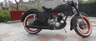
Motorcycle Features
The IZH Plante 5 motorcycle has the original name IZH 7.107. Just like the IZH 6, it belongs to the middle class of motor vehicles, designed for movement on roads with any surface. The main feature is the use of an oil pump; when refueling there is no need to add oil to the tank, as well as a contactless ignition system that operates independently of the battery.
It became possible to start a motorcycle from a pusher. To do this, you need to turn on the ignition, second gear and, when pushing the bike forward, the engine starts. True, without a battery, operation is possible only during daylight hours.
Pipes muffler Izh Jupiter Planet 5
The engine of IZH motorcycles is two-stroke, so the fuel combustion process is noisier than a four-stroke engine, and a larger amount of unburned gases is also released into the atmosphere. At the moment of release, the exhaust gases have a high temperature that is dangerous to the health of the motorcyclist.
Continue reading →
Distinctive features of electrical equipment
The wiring diagram used on IZ Planet 3 was traditional, and the main parameters of the electrical equipment are presented below in the table.
| Ignition system | Battery, ZMTR-10 |
| Mains voltage | 6 volts |
| Electricity source | Generator G-35M7 (later replaced by a modified G-36M8), 45 W |
| Ignition coil | IZH 56 |
| Voltage regulator relay | IZH RR-1 |
| Electrical wiring IZH Planet 3 | Single-wire, with “-” output to ground |
Colored original diagram (clickable)
Lighting devices
The following lighting devices were installed on the IZH Planet 3 motorcycle:
- Left and right direction indicators with A6-6 lamps;
- Turn signal switch P201;
- Turn signal relay RS-419;
- Brake light bulbs A6-15;
- Side light bulbs A6-2;
Appearance of instruments and controls
- Light mode switch with sound signal button P200;
- Transmission position sensor (neutral) with warning lamp A6 0.25;
- Headlight lamp A6-32+32;
- Indicator lamp A6 0.25 generator operation;
- Side light lamp A6-2 (front);
- Speedometer scale illumination lamp A6-1;
Headlight and direction indicators
Attention! For lovers of the “original” and authenticity, the photo below shows the “native” black and white wiring diagram of IZH Planet 3 with a breakdown of all the elements.
Lighting devices for models with a stroller
Added to the existing list:
- Stroller brake light lamp A6-15;
- Stroller size lamp A6-2;
- Right direction indicator for stroller A6-6;
- Front side light of stroller A6-2.
Option with stroller
Note! The standard wiring of the IZH Planet 3 provided for disconnecting the sidecar for operating the motorcycle without it in a two-wheeled version. At the same time, the connecting terminals required care.
In the presented video you can watch the repair of an old motorcycle, which received a new life in capable hands. According to the author of the video, complete restoration cost him the equivalent of $130. Moreover, he did most of the work with his own hands.