Nowadays it’s rare to find a “Planet” anywhere, especially in stock form. Grandfather's sheds where they once stood in abundance have long been cleaned out by the suffering, and the garbage dumps where they once lay are overgrown with grass...
The only place where you can still find something more or less decent is local newspaper advertisements. You can also search on Avito, but before you buy it there, see the product in person, otherwise they will send you a bag of bricks instead of an engine...
I was lucky: I found an advertisement in a local newspaper for the sale of an engine from a sidecar, went to the place, inspected it, made an agreement, bought it and brought it home. Don’t let the fact that the engine is from a motorized stroller scare you - the engine is completely identical to the original Planetovsky one.
In general, when I tossed the engine around, I was happy and immediately upset... I was happy because the engine was stock and had no signs of interference. There was also original oil and a USSR spark plug. I was upset because the piston and lower connecting rod bearing were killed.
I had a good factory cylinder in stock: bored to repair size + a factory piston, chrome rings and pin were purchased for it a long time ago.
I bought the connecting rod from an online store. We managed to find a factory one - not plasticine. I modified it a little: I made a small cut in the lower head to improve bearing lubrication, decompressed the crankshaft, threw out the old connecting rod, installed a new one and then centered the crankshaft using an indicator.
Engine assembly IZH Planet 5
The engine assembly process occurs in the reverse order, with the obligatory condition that all technological features of the process are observed. When restoring the motor, do not forget that this is a precise mechanism and its main characteristics will depend on how carefully you approach the fitting and installation of all parts.
- All dismantled spare parts and engine elements are washed with solvent and an inspection is carried out. If serious chips, scuffs or other defects are found, these parts are replaced. If the left half of the crankcase or the right is damaged, then they are replaced in pairs.
- The joining surfaces are cleaned of traces of sealant or gaskets.
- The elements of the gear shift assembly are polished to a shiny surface.
- We fill the left oil seal with grease and install it in place with the bearing ring, followed by a shaped washer.
- We install the retaining ring, after checking the accuracy of installation, proceed to the next steps.
- Next we mount the main bearing rollers and lubricate them.
- We put on the crankshaft and place a ball bearing lubricated with grease on it.
- We install spacer washers and follow them with a retaining ring.
- Let's see how easily the crankshaft rotates after lubricating it with engine oil.
If assembly at this stage does not cause any complaints, the following steps correspond to the reverse order of engine assembly. Please note that you need to purchase a complete set of new gaskets, and additionally lubricate the connecting surfaces with heat-resistant sealant.
Source
Preparing for assembly
Preparation for assembly can be divided into two main stages: measuring and, if necessary, eliminating the axial play of the tracer shaft and checking the suitability of the secondary shaft bearing for further operation.
The first stage is measuring and eliminating the axial play of the copy shaft
We put adjusting washers on the tracking shaft from the locking side. In my case, there were four adjusting washers, but you may have more or less, or maybe not... We move the locking bar to the side and install the copy shaft in its place. We put a standard thrust washer on the second end of the tracing shaft.
We place a new gasket (required) on the plane of the gearbox cover connector, on which you will later finally assemble the gearbox, and tighten the gearbox cover fastening screws with the required force.
We turn the engine over and measure the axial play of the copy shaft, the norm is 0.2-0.4 mm, but it will be better if you can ensure the axial play at a level of no more than 0.2 mm. Adjustment of axial play is accomplished by simply adding or removing shims.
I measure the play with an indicator. If you don’t have one, try measuring the backlash with a caliper; if you don’t have a caliper, so be it - measure by eye...
Second stage: checking the suitability of the secondary shaft for further use
Under normal operating conditions, the secondary shaft bearing runs for quite a long time. But no matter how much we want and try, it wears out. It would be nothing if it weren’t for safety: if your secondary shaft bearing falls apart while driving, and it will certainly fly apart if you don’t change it in time, the gearbox sticks together with the rear wheel, and it’s tight and you’re grinding the asphalt with your butt...
Carefully, take out the secondary shaft over some tray and carefully inspect the shaft bearing raceway, the races and the rollers themselves. The working surfaces of the bearing and rollers should be free of holes, edges, signs of wear or overheating
The path must have a perfectly flat working surface.
Example of a secondary shaft race and race in perfect condition.
To facilitate reassembly, apply some kind of lubricant, such as lithol, to the treadmill and carefully place the rollers on the track and, turning it a little, insert the shaft into the cage. As soon as the sprocket splines rest against the edge of the oil seal, use a thin screwdriver in a circle to straighten the edge of the oil seal and push the shaft until it stops. And immediately, so that the shaft does not fall out, put the sprocket on it and secure it with a nut.
Tuning the IZH Jupiter engine
Before you start, you need to decide how much power you would like to give to your engine. If you are quite satisfied with the average power, then you will need a ZiD-200 resonator. But if you want to make the IZH Jupiter 5 motorcycle fast and powerful, start tuning the engine by installing a resistor from the SMB-5 “motoblock”.
Replacing the air filter plays a big role in engine modification. The better the air is cleaned, the more horses the engine will be able to produce. After all, the degree of engine overheating depends on the amount of incoming air. It is best to use imported air filters. They provide improved cleaning and longer service life.
Next you should work hard on the injection system. An excellent option is to install a “Planet” carburetor with a diffuser diameter of 0.32 cm. Two carburetors will provide much greater acceleration and good dynamics. We take the flanges securing the cylinder from the standard tube, grind out the aluminum studs, and cut off the flange from the carburetor from the inlet tube from the Planet.
We grind the ends of the cylinder heads on a machine, and press the cylinders themselves. The maximum permissible volume of PIC is 18 cubic meters. see Install factory copper layers under the cylinder heads. And we adjust the ignition advance angle to increase compression.
We use the second flange from the old carburetor. Then we weld the parts using “cold” welding. And finally, we modify the assembly to be compatible with the inlet channels. We fill all the cracks with epoxy liquid. Voskhod carburetors will ensure uniform traction. In this simple way, you can add not only a couple of extra horses to your pet, but also provide more lively dynamics, giving a good riding experience. The motorcycle is very reliable for everyday use, and if you provide good care, then breakdowns will occur very rarely.
When is it necessary to repair and adjust the gear clutch on an Izh motorcycle?
Regardless of the amount of experience the motorcyclist has, the feelings regarding gearbox malfunctions are almost the same:
- At first it seems that the clutch is slipping slightly. After two or three days, confidence appears - yes, it is slipping, because as soon as you add speed, the acceleration rate lags behind the engine speed level. The breakdown is especially obvious when moving uphill.
- The clutch “leads” or the clutch is incompletely disengaged when the control lever is depressed. In such a situation, the disks of the assembly remain pressed against each other and do not stop transmitting torque to the gearbox. You can finally verify such a breakdown after lifting the rear wheel - it continues to rotate in this situation.
If you want to know how to adjust the clutch on an Izh-Jupiter 5 motorcycle, then information about the reasons causing the listed factors would be useful:
- Use thicker oil in winter.
- Weakening of pressure springs.
- Worn clutch discs.
- Wear of clutch control mechanism elements.
In most cases, if signs of slipping or incomplete disengagement of the clutch are detected, a simple adjustment of the mechanism is required. To do this, it is enough to have a “13” key and a slotted screwdriver.
In what cases is ignition adjustment necessary?
During the operation of the vehicle, the owner faces many problems. The most serious failure is related to the engine. In order to spend significant funds on major repairs, it is necessary to monitor the technical condition of the motorcycle and carry out preventive work, including adjusting the valves and valves (video author - Hana Rulyu).
If you do not monitor the SZ, then the motorcycle engine may not reveal its full potential and will not work at full capacity. This can lead to a reduction in its service life. An ignition adjustment is necessary if the engine is running poorly, the muffler or carburetor is firing. True, before setting up the SZ, you should make sure that the cause of the malfunction is in it.
It happens that the flywheel bolt, which connects the two halves of the crankshaft, comes loose, begins to play and does not work well. Sometimes he even cuts the key.
Setting up the SZ may be necessary after repairing the ignition switch Izh Jupiter 5. The installation and connection itself are carried out according to the diagram.
SZ diagram of the IZh motorcycle
Which 2505 is installed in IZh or Ural?
Unfortunately, it’s difficult for me to answer this question, because... the first reference book says that they install bearing 2505 AEM - 10 GPZ with tectolite, and the second 2505 KMU (the plant is not specified). High-level specialists, whom I have no reason to distrust, claim that 2505KMU has always been there. Ideally, if there was an IL on which the bearings were not changed, everything would become clear, but since... IZH has not been produced for 10 years, the likelihood of this dropping every year.
My opinion doesn’t matter what. Structurally, they are absolutely identical in size and geometry, which means that on such a relatively simple unit as an IZH crankshaft, the bearings are interchangeable. According to generally accepted standards, textolite is less noisy and the metal is more reliable. Therefore, decide for yourself, but if you know for sure, do not be lazy - write to the chat or email, I will be grateful.
Installation of bearings and seals
We install a retaining ring in the left half of the crankcase.
Depending on the model of the main oil seal, we install a spacer sleeve in the mounting hole of the main bearing, or, if the oil seal was initially wide (there are some), we heat the crankcase and, on the inside of the crankcase, place the oil seal until it stops against the retaining ring.
My engine had a regular narrow oil seal, so I put in a bushing.
Using a mandrel, install the main oil seal into the preheated crankcase.
Quickly, before the crankcase cools down, place the oil guide washer on the oil seal. The oil guide washer has a saucer-shaped profile. We place it on the oil seal so that the concave side faces us, and the curved side faces the clutch basket.
While the crankcase has not cooled down, we press the outer race of the main bearing into it using a mandrel.
If you are going to replace the main bearings with new ones, don’t be lazy: find a sheet of iron 7-8 mm thick, cut a wedge in it for the connecting rod, pass the sheet of iron between the cheeks of the crankshaft and use a mandrel to drive the main bearing onto the axle.
This way you will protect yourself from damage to the crankshaft. The main bearing has a very high interference and fits into the axle with a very large force. It is not uncommon for people to simply knock out the axle (the axle on the planetary crankshaft is pressed into the cheek) inside the crankshaft, but they were never able to put the bearing on.
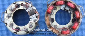
Native made in USSR 2505 KM
Preparation
To perform a high-quality repair, the engine parts must be clean, the threads in the crankcase must be threaded, the seals and gaskets must be new.
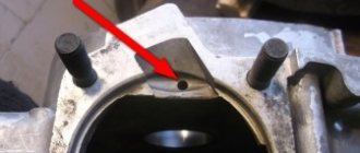
First, we clean the oil channels in the crank chambers. There are two channels in the Izh-Planet engine: one in the left half of the crankcase, the other in the right. We find the channels and if they are very clogged, we clean them with wire, rinse them with clean gasoline and blow them with compressed air.
Photo report: Repair (repressing) of the crankshaft of the Izh-Planet motorcycle - SCOOTERS AND MOTORCYCLES
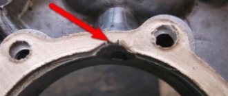
Due to a gross design miscalculation, the crankshaft of the engine of the Izh-Planet (SZD) motorcycle, having traveled some measly 5,000 km, successfully “grunted” (knocked). Even Chinese plasticine goes through many times more, but here is “Planet”. How so? Of course, to clarify the picture, it’s worth making a little reservation: The crankshaft, the repair of which will be discussed in this article, is slightly different in design from the original “planet” one, since it is from the SZD (motorized sidecar) engine. But in essence, there is practically no difference between these shafts and engines. The reason for the rapid failure of the crankshaft was that the bearing of the lower head of the connecting rod, due to a gross design flaw, was not at all lubricated with oil during operation.
Here, that same depression in the cheek, of unknown purpose. But the oil channel (ordinary chamfer) on the “native” connecting rod, the channel must be said: it was made to “fuck off”, and it’s not a channel in essence, but another Soviet bullshit ( Even the Chinese don’t allow themselves to do this). Through such a channel, lubricant cannot even theoretically flow to the bearing. Now look, if you put a new connecting rod with developed channels for lubrication, then all the same, the channels are blocked by the walls of the recess. Our task for today: Install a new connecting rod, instead of the old one, in the crankshaft, having previously taken care of its normal lubrication. And then, the whole thing must be carefully aligned using special measuring tools. First, the crankshaft must be disassembled.
We place the crankshaft on the sheet. We lay the sheet on some powerful beams so that the crankshaft journal hangs freely in the air, take a suitable mandrel, place it on the finger and use a heavy sledgehammer to knock the finger out of the cheek. After removing the finger from one cheek, take the second cheek, place it on the sheet and knock out the finger in the same way. Before removing the finger, remember the main rule: Never try to knock out a worn finger all the way through the second cheek! During engine operation, the working surface of the bearing pin of the lower connecting rod head takes on an elliptical shape, so if you decide to knock out the pin with a worn surface through the cheek, the result will be the same - you will violate the geometry of the hole for the pin in the cheek. Because of this, the new finger will no longer stay in such a hole! Previously, a new connecting rod was purchased from the online store (factory-made, not 100% made in China). We are looking for the thinnest and most worn-out diameter cutting disc for the grinder, prepare a container with water in advance, install the disk on the grinder and proceed to finalizing our connecting rod
Such a groove is quite enough to lubricate the bearing; as you can see, due to the timely cooling of the part with water, there are completely no traces of blue. After cutting the groove, we take the files and carefully sand all the burrs, sharp corners, “other jambs” both inside and outside. The connecting rod is modified, now you can start assembling. We lay any cheek on some flat surface (preferably wooden) and Using a mandrel, a heavy hammer or a small sledgehammer, we drive the bearing pin into the cheek. Be careful that your finger does not stick out of your cheek. We put the support washer on the finger, then we put the connecting rod with the pre-washed bearing there and put the second washer on top.
You shouldn’t push the cheeks together too much; bring them together so that there is a small gap (0.15-0.2 mm) between the connecting rod and the cheek. The final stage in all this work will be the final alignment of the crankshaft.
In case of any discrepancies in the thickness of the crankshaft, we either move the cheeks in the desired direction or compress them. Until the thickness of the crankshaft in all measurement locations is absolutely the same.
After we have equalized the thickness, we place the crankshaft on the prisms, install the indicator on the stand and proceed to the final one. We turn the crankshaft so that the indicator arrow shows maximum runout. We take a chalk and put a mark along the axis of the indicator. We take a metal plate, cover it with a sheet of some non-ferrous metal, in our case the role of the non-ferrous metal is played by a piece of lead. And lightly hit (where the mark is) with the marked cheek on the slab. Afterwards, we install the crankshaft on the prisms and check the runout, and repeat this until we can reduce the runout of the axles to the minimum possible value (no more than 0.03 mm).
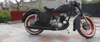
Hi all! I take this opportunity to wish everyone a Happy New Year! I have accumulated enough material to write a post about the repair of the IZH-Planet 5-01 motorcycle, which I purchased last September. Things didn't go quite according to plan, which is why this story will stretch into 2 parts. In order to understand what kind of motorcycle this is and how it all started, I advise you to read the previous post about buying a motorcycle and starting to repair it. A short story about how our regiment arrived. Buying a motorcycle IZH-Planet 5-01. Everyone is welcome - you are welcome 
So, we prepared all the parts for painting and soon took them away. As planned, we welded the frame in some places and strengthened the base of the saddle. While all the parts were being painted, I decided to rebuild the rear shock absorbers. Surprisingly, they were in excellent condition. What I liked was that they had rebound springs, which FINALLY eliminated the knocking noise on reverse. I replaced the silent blocks, seals, oil and everything worked great. Oh yes, I also replaced the shock absorber itself with a chrome one.
And here is heart 5-01. How much work it took me to wash it! I had to buy the most severe chemicals and wash it. What’s interesting is that if you compare the 3 engines of this model that I have, they are not similar to each other in some barely noticeable ways. Take this engine for example - the left engine cover is fastened with 8 screws (I don’t know why there are so many. Previously it held on just fine with 5). There is also an additional screw installed between the crankcase halves. The cylinder jacket now has solid bars. Interestingly, such fins with vibration dampers and an enlarged air filter significantly reduce engine noise, if we take the usual five as an example. In the end, after washing, the engine was wiped dry, preserved until better times and put on a shelf. And here the question is - why? Why remove it? I'll tell you about this now.
In the summer, my Planet-6 behaved extremely disgustingly! As a result, she turned back to Planet 5-01. What did she bring? Ooooh, I'll tell you now.
Of course, I am not a supporter of the perversion of replacing the engine 2 times a season, but this summer the engine showed all its weaknesses, and at once! It all started with a little thing. Well, as a small matter... I decided to go for a ride in the evening. I went far and here you are! Crunching, knocking... I turn off the engine, try to turn it over with the kick starter - to no avail. The culprit was a loose bolt on the clutch basket, which got stuck so conveniently that it popped the engine cover a little and all my oil leaked out... I fixed it.
Further, not far from the house, the oil pump broke down. Although it’s a small thing, drain the oil from the oil tank and change the pump. Unpleasant... Fixed it.
Further. I went to a neighboring village. I’m driving and feel that suddenly the air has started to leak and the engine is barely running. I looked for the reason and found it. It's all because of the rubber connection between the carburetor and the inlet pipe. This PS system has failed. The rubber band cracked, and it was new, less than a week had passed since purchase. I found a package on the side of the road, wrapped it up, and arrived. It was starting to get annoying.
And then the engine did not develop power at all. The break lets absolutely everything pass between the halves. Yep... This means removing the engine, radiator, completely disassembling the engine. Challenge accepted!!! The fears were confirmed. After the engine was cut in half, I was horrified. What kind of game is this!? And not sealant or varnish!? What is this? Everything was shriveled up, the oil was consuming as much as it could! This is a huge disadvantage of a non-serial engine. I don’t know how my engine was assembled, and who assembled it, that I removed all the jambs until the last minute.
The crankshaft is PS, but the left axle is from a regular planet.
Gap after running in. Well, it's really a shame!
Welded plate for installing the cylinder. Such a plate was on the first engines, then they made it more aesthetically pleasing.
I wash everything and examine every millimeter for the presence of something else... you never know there will be more jambs. As a pathologist, only with IZH.
Well, that's it, you can put it back together. Replaced engine seals and rings. And now, slowly, let’s degrease everything, blow it through and assemble it as it should be. No engine has ever driven me as hard as this one. Well, why did it die after the run-in? Well, not completely dead, but damn... Of course, you can understand - the engine is non-serial, semi-tested... Well, it was possible to assemble it normally? So we'll collect it. Before assembly, as always, we washed every screw so that everything was Feng Shui.
To assemble the engine, almost the way it should have been assembled at the factory, I used the factory documentation for this particular engine. Here you can say: forget it already, stop messing with it! I thought so myself at that moment, maybe that’s enough!? But nooo, that would be too easy. Once you get it, do as Mayakovsky wrote: don’t groan, don’t gasp, don’t pull the reins, once you’ve fulfilled the plan...
That's it. Assembled, installed, started, drove off. Well, that's a completely different matter! I went as I should! Ahh... what's that there? Is the cylinder head leaking? Yes, yours... well. That's enough, go on the shelf until better times. Moreover, the trip to Izhevsk was approaching, and driving such an engine was stupid. And on this note, the reliable 5-01 returned to service. This is roughly how the engine finished me off))) And now we’re moving back to repairing the new motorcycle. That's it, I started preparing for assembly. I bought a lot of original new spare parts. I decided to take the trouble and change the knitting needles. We also found another head from the P6 engine - one as a spare.
The second head also had a small jamb, but it didn’t matter. By that time I had calmed down and took both heads to an argon specialist, where they fixed everything for me without any problems. Well, let's begin!
Everything was painted. We begin the assembly procedure
I had another Orion fork in stock and decided to put it here. Moreover, this frame has a different angle of inclination of the steering column and is precisely adapted to this fork. This frame also allows you to install a P6 engine and a radiator, and everything will fit and will not rest against the tank, as on a regular frame. This is what prompted me to return to assembling Planet 6. I don’t know what kind of stubbornness this is, but I want to have such a motorcycle and ride it.
After all the assembled motorcycles, this one was assembled faster, almost automatically.
This fork also has a different type of headlight holders and reflectors. Reflectors have their own mount. I wanted more chrome parts on this bike, and because of this I decided to go with spoked wheels.
Almost new rear casing. The most interesting thing is that almost all the fasteners remained original, since after a week of soaking in gasoline it was like new.
He turns out handsome)) I believe everything will work out!
We begin installing controls, wiring, and a rebuilt instrument panel. I had to tinker with the panel. Here the oil lamp was not used. We ran the wire to the oil tank, wrapped it in heat shrink, put it in the tidy - everything worked.
Like from an assembly line. Maybe a little better)))
All plugs with covers. It’s a pity that there’s no such thing on the fours, there’s nothing scary about the wiring here in the rain.
Here he is) Taking his place of honor.
We ran the wiring and went through all the hydraulics. All that remains is to connect a couple of wires correctly and you can try connecting the battery to check.
Everything is working! You can fasten the wiring to the frame soon.
I wanted to remove the carbon deposits, but there was almost none. A huge plus of separate lubrication is that there is much less carbon deposits.
Here I also sealed the fender liner to prevent dirt from getting in from under the wheel. On another Planet 5-01, this small modification showed itself to be excellent - now there is no dirt at all on the BPV, switch and wiring.
I cleaned the muffler and elbow from carbon deposits. For the first time, I came across a whole muffler, everything was like new, I just had to wash it off the dirt and polish it.
Slowly the motorcycle is acquiring everything it needs.
We reupholstered and assembled the saddle. We put the glove compartment covers on. I'm already starting to like it)))
Another moment when I almost went crazy was replacing the spokes. It seems like I’ve almost removed the figure eight and an oval appears. In 2 weeks I was unable to completely eliminate the runout and straighten the wheel. The front wheel works more or less, but the rear wheel doesn’t want to. This is my first time changing spokes, and to be honest, I didn't have the patience. I will give it to someone who knows. Of course, I have to do it myself, but I hate wasting so much time.
The cable divider also caused problems. The divider itself is from a Honda Dio. I had to make an analogue cable for the throttle grip, since the cable from the carburetor and oil pump were original. An hour of magic with a soldering iron and everything was ready and worked no worse than the original. Another plus of IZH is that it will make you a mechanic, an electrician, teach you how to solder, make the necessary parts, and... ahem, of course it’s no secret, it will teach you to swear.
There are so many wheels missing)) Almost everything is ready. While the wheels are being made, while the new Mitas tires arrive, all the little things can be eliminated and all that remains is to lower it to the ground))
With this I will summarize the first part. This is such a muddy story with the engine. Even though it got on my nerves, I will still do it properly. It would be too easy to leave it on the shelf when the finish line is just around the corner. The most amazing thing is that the assembly time took 2 times less than last year, so you won’t have to wait long for the second part. Still, it was not in vain that I bought this motorcycle, what a beauty it turns out to be, I really like it myself)) This is how our winter garage season goes)) Once again, Happy New Year to everyone, thank you for your attention, see you again!
Assembling the crankcase halves
We degrease the connector of the halves, knock out the guide bushings a little so that they extend 5-6 mm above the plane. Depending on your desire, we assemble the checkpoint. Personally, I assemble the gearbox only after assembling the engine, it’s more convenient for me.
We apply any automotive sealant to the connector, install the second half of the crankcase, tap it with a mallet, install the gearbox cover and tighten the crankcase with bolts.
We do not pull the bolts anyhow, but strictly according to Feng Shui: we pull about a third of the force, first the middle crosswise, then the periphery, and gradually increasing the force over several circles, we tighten the bolts as much as is sufficient.
Assembly
In a carefully washed and prepared for assembly crankcase we place the input shaft, the first gear gear and the follower shaft with pre-selected shims.
We put a fork on the gear-carriage for engaging the second-fourth gear (it is smaller than the gear-carriage for engaging the third-first gear, you can’t go wrong) as shown in the picture. We put the gear on the input shaft and insert the fork pin into the upper groove of the follower shaft.
We put a fork on the gear-carriage for engaging the first-third gear, as shown in the picture, place it on the first gear gear and insert the fork pin into the lower groove of the copy shaft.
We install the fork guides in their places (with grooves towards the clutch basket). By the way, if necessary, the “Planetovskaya” gearbox can be assembled and disassembled without disassembling the clutch basket and without removing the guides. But to do this, during installation you will have to pull the tracing shaft towards you a little, insert the pins of the forks into the grooves and after that, remove the locking bar and push the tracing shaft all the way.
Install the intermediate shaft.
On older engines, the end gear is installed separately. On later ones, it is made integral with the intermediate shaft.
We fill the return spring of the gear shift shaft as shown in the picture.
We check the functionality of the gearshift shaft pawls: compress and unclench them several times
We pay special attention to their working edges: they should be sharp and not licked. And don’t forget to check the spring that compresses the pawls: it must be of the correct shape and ensure the elasticity of the pawls’ movement
We squeeze the pawls and install the gear shift shaft in its place.
We rotate the tracking shaft with the mark on the body towards the gear shift shaft and so as not to miss the mark during installation, we cover the gap between the teeth opposite the mark of the tracking shaft with lithol or paint it. It will be more noticeable this way.
We look for a mark on the sector and when putting the sector on the gear shift shaft, we combine the mark on the sector with the mark on the tracking shaft body: the tooth opposite the sector marks should strictly fit between the teeth opposite the mark of the tracking shaft.
To ensure that our marks do not get lost during installation, we tie together the sector and the copy shaft with ordinary sewing thread.
We put standard thrust washers on the input and follower shafts and insert the guide bushings of the gearbox cover into place.
We degrease the surfaces, apply sealant, lay the gasket, install the cover and tighten the mounting bolts with the maximum possible force. We adjust special washers under the bolts marked with yellow arrows.
After tightening the gearbox cover, we check the axial play of the primary and secondary shafts. Normal: 0.2-0.4mm.
If the play is greater than normal, remove the plate, seat the bearing and adjust the required number of shims under it.
Engine IZH Planet 3, 4 and 5, disassembly, assembly for repair and tuning
When disassembling the engine, you must first drain the oil from it and remove it from the motorcycle frame; you must wash the engine thoroughly. To do this, it is advisable to use a high-pressure apparatus (car wash) with car shampoo. Having washed the engine and protected it from getting dirt inside, we proceed to disassembly.
We remove the right engine cover, remove the generator (by unscrewing the mounting bolts). Be careful not to damage the paronite gasket; remove the cover and disassemble the box. We take out the gears with the shafts and disassemble the shift mechanism, remove the control levers from the engine, and remove the clutch cover. We completely disassemble the clutch and remove the motor chain. We disassemble the piston, remove the cylinder head (by unscrewing the fastening nuts), then remove the cylinder. After this, remove the piston from the crankshaft, having previously removed the retaining rings and carefully knock out the piston pin. We place the engine on its left side and carefully, without damaging the heads, unscrew the connection bolts, using a powerful screwdriver. Then we knock out the centering halves of the crankcase half the length of the bushing.
Disassembled parts must be washed in gasoline and carefully inspected; damaged and faulty parts must be replaced with new ones. Clean the junction of the crankcase halves from old glue
On the oil seals (cuffs), pay attention to cracks and springs. Bearings should rotate easily without jamming and should not have any play
Having prepared serviceable parts, we begin assembly. We assemble the engine in the opposite order of disassembly. Be sure to heat the crankcase half to the same temperature, which makes assembly easier and preserves the crankcase surface from damage during pressing. The connection of the crankcase halves must be coated with BF-4 glue. When installing the piston on the crankshaft, it is advisable to heat it to a temperature of 60 degrees, this will help when inserting the piston pin. During assembly, you also need to lubricate the cylinder mirror and piston pin with engine oil.
How to adjust a motorcycle clutch?
As always, we delve into theory.
Junker's clutch type is multi-disc in an oil bath. On the left, on the gearbox shaft, sits a basket with alternating disks, thin steel and thick getinaks. They are pressed against each other using 5 (or 6) powerful springs. Getinaks disks are connected to the basket (and, through the motor chain and 2 sprockets with the crankshaft), and steel ones are connected to the gearbox shaft (and, through the gearbox, actually to the wheel). The springs are so powerful that the entire power of the engine, without slipping (and the disks are all in oil) is transmitted to the rear wheel. Next, when you press the clutch lever, the cable pulls the lever (it sits on the right engine cover - look), which pushes the steel rod (it passes through the axis of the drive sprocket, you can take it out and turn it in your hands), and this rod rests on that part a basket with disks, which is connected to the getinax disks, and they, overcoming the resistance of the pressing springs, move away from the metal disks. That's it, the clutch is loose. The engine with its getinaks disks rotates on its own, the steel ones with the gearbox stand still. Attention! There is more than one push rod. There are 2 of them, and between them there is a ball from the bearing (eliminates rotational force). Easily lost! Be careful when disassembling, otherwise you will end up with a failed clutch.
Now about the adjustments.
The clutch is adjusted NOT ON THE HANDLE, but by changing the force of pressing the discs against each other. The free play of the cable is simply selected on the handle. The force of pressing the disks against each other is regulated by preloading the springs, on which, for adjustment, “fungi” with a groove for a large flat-head screwdriver are put on. Access to these “fungi” appears by unscrewing the cap on the left engine cover (the hole through which you pour oil into the engine). And not to all of them at once, but only to a part – i.e. to adjust everything you will have to rotate the crankshaft with a kickstarter
IMPORTANT! All springs must have the same preload! Those. all mushrooms twist at the same number of revolutions
Or rather, half a turn - a turn is too large an adjustment step.
What to do if the clutch slips?
1. Make sure that the clutch handle has free play and that you have not unscrewed the adjuster on the handle so that the clutch is constantly depressed. 2. Open the left cover (no need to drain anything, at the same time check the oil level in the engine on the dipstick - it should be between the marks) and evenly, carefully tighten all the fungi half a turn. We start the engine, check the clutch operation, if it still slips, turn it off and repeat the procedure. At the same time, we look at the condition of the teeth on the textolite disks - if they break off on some disk, then it begins to rotate with the steel disks and the clutch operates. Good official Hyundai dealers will help you make the right decision. For an office move, movers are indispensable, I recommend Best-Loader.Ru. Wheel storage in Moscow. What to do if the clutch does not disengage?
1. See paragraph 1. higher. 2. See point 2 above, only the fungi are unscrewed half a turn. Well, the reasons for a driven clutch are natural wear of the discs, weakening of the springs, breaking of the protruding teeth on the getinaks discs, pulling out of the cable and LOSS OF THE BALL when repairing a motorcycle.
Now about what a semi-automatic clutch is.
When you change the speed, the shaft on which the gear shift paw sits turns, and with its fork protruding into the right cover, it presses on the clutch lever (the same lever to which the clutch cable fits and which presses on the steel rod), and thereby duplicates the pressure on the clutch handle by hand. And don’t blaspheme the semi-automatic in vain! A very necessary and useful thing! Firstly, your clutch cable has simply never broken on the road - it’s impossible to get going without a semi-automatic vehicle. Secondly, on the road, starting from 2nd speed, I never used the manual clutch at all - there was no need. When changing the speed, I simultaneously disengage the clutch, change the speed and smoothly engage the drive! (You make one move, oh IT makes 3!
) The only thing is that it’s inconvenient to get going with a semi-automatic vehicle if you’re not used to it, but it’s quite possible.
Assembly and disassembly of the IZH Planet 5 engine
Domestic motorcycles of the IZH brand, despite their age, are still popular in various parts of our country. This simple and unpretentious transport is especially popular among residents of rural areas.
Not every imported motorcycle can start at +40 or -30, run on any gasoline, and when modified with a sidecar, it turns into a universal transport for a hunter or fisherman. Unfortunately, these motorcycles also have a significant drawback - low engine life. It’s rare that an IZh can work for several seasons and not fail.
That is why below you will find step-by-step instructions on how to disassemble and reassemble the IZH Planet 5 engine.
Following the diagram below, you can get to all engine elements in order to inspect or replace them. It makes sense to completely disassemble the engine if you need to get to the crankshaft or left oil seal.
Failure of the latter leads to a decrease in driving characteristics and smoking due to the presence of a large amount of oil inside the crank chamber.
Step-by-step disassembly diagram:
- Unscrew the spark plug and nuts from the top of the cylinder. We remove the cylinder with the piston.
- We drain the remaining oil in the engine and remove the engine from the frame (mounts in the front and rear), having first disconnected and numbered all the wires.
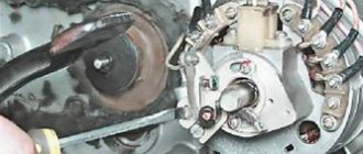
- We unscrew the left cover and remove as much as possible the gearbox and other accessible elements.
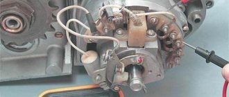
- From under the right cover we remove the generator, the final drive sprocket and the crankshaft oil seal.
- We remove all accessible parts related to the gearbox.
- On the right we find the screws that tighten the crankcase parts. We unscrew them together with the nuts of the two bolts.
- Use a rod of suitable diameter to push out the installation sleeves so that they partially remain in the grooves.
- Using a mallet, lightly tap along the entire plane of contact between the crankcase parts. If the parts do not move away from each other or come off partially, try inserting a mounting blade into the groove and tapping it without much force.
- Unscrew the locking plate and remove it.
- We take out the ring-washers, simultaneously noting their order.
- The left side of the crankcase can now be removed from the crankshaft. If the element does not give in, you can use light blows with a rubber hammer to help the parts separate.
- Using pliers, remove the retaining ring. To remove ball bearings, you will need a pipe or similar element, the end of which coincides with the outer race of the bearing. We lean it against the bearing and little by little knock it out of its mounting position.
- By lightly tapping, remove the guides of the gear shift units.
- We take out the retaining ring installed inside, and behind it the split remote ring.
- Press in the left oil seal. Similarly, we take out the main bearing ring installed on the right.
Engine disassembly is complete, now you can repair the IZH Planet 5 engine.
Engine assembly IZH Planet 5
The engine assembly process occurs in the reverse order, with the obligatory condition that all technological features of the process are observed. When restoring the motor, do not forget that this is a precise mechanism and its main characteristics will depend on how carefully you approach the fitting and installation of all parts.
- All dismantled spare parts and engine elements are washed with solvent and an inspection is carried out. If serious chips, scuffs or other defects are found, these parts are replaced. If the left half of the crankcase or the right is damaged, then they are replaced in pairs.
- The joining surfaces are cleaned of traces of sealant or gaskets.
- The elements of the gear shift assembly are polished to a shiny surface.
- We fill the left oil seal with grease and install it in place with the bearing ring, followed by a shaped washer.
- We install the retaining ring, after checking the accuracy of installation, proceed to the next steps.
- Next we mount the main bearing rollers and lubricate them.
- We put on the crankshaft and place a ball bearing lubricated with grease on it.
- We install spacer washers and follow them with a retaining ring.
- Let's see how easily the crankshaft rotates after lubricating it with engine oil.
If assembly at this stage does not cause any complaints, the following steps correspond to the reverse order of engine assembly. Please note that you need to purchase a complete set of new gaskets, and additionally lubricate the connecting surfaces with heat-resistant sealant.
Maintenance and repair
5.18 Reinstalling the crankshaft and measuring the radial clearance of the main bearings
Reinstalling the crankshaft and measuring the radial clearance of the main bearings
Selecting new bearing shells
Inspection of main bearings and connecting rod lower end bearings
Measuring the radial clearance of the main bearings
EXECUTION ORDER
1. Clean the backs of the bearing shells and their beds in the cylinder block and in the main bearing caps. 2. Insert the bearing shells into place, making sure that the protrusion on each shell matches the notch in the cylinder block or main bearing cap. Try not to touch the working surface of the earbuds with your fingers. 3. Radial clearance can be measured by two methods. 4. The first method (which is more difficult to implement as it requires the use of an internal micrometer set or an internal/external flaring caliper) involves installing the main bearing caps into the cylinder block/crankcase with the bearings installed in them. After tightening the mounting bolts to the required force, the inner diameter of each pair of bearing shells is measured (the crankshaft does not need to be installed). After measuring the diameter of each corresponding crankshaft journal, to obtain the radial clearance, it is necessary to subtract the second from the first result. 5. The second (more accurate) method involves using a product called a plastic gauge (Plastigauge). The gauge is a thin plastic thread of absolutely circular cross-section, which is crushed between the bearing shell and the crankshaft journal. After removing the lid and liner, the width of the crushed thread can be measured using a special scale printed on the kit packaging. The gap is determined by the width of the crushed thread of the meter. The measuring set can be purchased from a Saab dealer or vehicle repair shop. When using a plastic meter, proceed as described below. 6
Once the upper main bearing shells are in place, carefully reinstall the crankshaft. Do not use any lubricants at this stage; The crankshaft bearing journals and the surfaces of the bearing shells must be absolutely clean and dry.
7
Cut several pieces of plastic thread to the required size (the length of each piece should be slightly less than the width of the main bearing), and lay each piece on the corresponding crankshaft journal coaxially with the journal. A piece of plastic thread should be laid approximately 6 mm to one side of the center line of the neck.
8. After installing the lower main bearing shells, reinstall the main bearing caps and tighten the bolts in a progressive order to the required torque. Be careful not to move the gauge thread or rotate the crankshaft during the measurement procedure.
9. Loosen the bolts and remove the main bearing caps, being extremely careful not to disturb the crushed gauge threads or rotate the crankshaft.
10. Compare the width of the crushed plastic thread on each neck with the scale printed on the kit packaging. The measured value indicates the amount of clearance in the bearing. Compare the measured gap with the values given in the Specifications at the beginning of this Chapter.
11. If the clearance is significantly different from what is expected, the bearing shells may be the wrong size (or excessively worn if old shells are installed). Before you decide that you need to install liners of a different size, make sure once again that when measuring, no dirt or oil gets on the crankshaft journal or liners. If the crushed plastic thread of the meter is wider at one end than at the other, then this indicates the presence of a taper in the crankshaft journal. 12. If the gap value is outside those established by the Specifications
limits, select the thickness of the liners to ensure the required clearance. When calculating the required clearance, remember that it is always better to err on the side established by the Specifications
lower limit, since as the liner wears out, the thickness of the gap will increase. 13. If necessary, install bearings of the required size and repeat the procedure for measuring the bearing clearance. 14. Finally, carefully scrape the crushed plastic gauge thread from the crankshaft journals and bearing shells. To do this, use your fingernail or a wooden or plastic scraper that will not damage the bearing surface.
Final installation of the crankshaft
Crankshaft alignment
The crankshaft has been assembled, all that remains is to eliminate the runout of the shafts (balance), many people think that you can’t do this without a lathe, but everything ingenious is simple.
Measure each neck with a caliper as shown in the photo below, usually they are the same size, but sometimes they are slightly different in size. This dimension must be taken into account when aligning the crankshaft.
Photo. We measure the crankshaft cheeks.
All that remains is to attach the rod to the crankshaft cheek as shown in the photo below. It will be like this, first place the barbell on one cheek and press it with your finger, the barbell will lie perfectly flat on the cheek, if this cheek is shifted upward, a gap will appear between the barbell and the second cheek. If the cheek is lower, the bar will lie slightly obliquely.
Photo. A motorcycle crankshaft with a rod is shown; the arrow shows the gap between the rod and the cheek.
Your task is to achieve alignment of the crankshaft cheeks without gaps by applying the bar alternately to each cheek. The photo below shows how you can move the crankshaft cheek with a hammer blow. Just be sure to take into account the strength of the crankshaft cheeks, the crankshaft on which I am showing from a cross-country ChZet, it is hardened and is not afraid of impacts. But most of the crankshafts from road motorcycles have soft metal, so you can only hit the place where the bar is not applied.
Photo. This way you can move the crankshaft cheek.
If one cheek of the crankshaft turns out to be larger in diameter than the other, then when centering the crankshaft, take into account the gap between the cheek and the rod; this gap should be visually the same when applying the rod to the larger cheek on both sides.
Photo. The crankshaft of the motorcycle is centered, the rod lies without gaps on the crankshaft cheeks.
If you do everything right, everything will be correct, you will save money on a new crankshaft by replacing only the connecting rod on the old one, for this you only need your hands and a smart head.
A little history.
Bearing 2505 (according to GOST) is a rolling bearing, radial roller with short cylindrical rollers, single row. At all times, this bearing was produced in Saratov (3 gas processing plants) and Rostov (10 gas processing plants). The directory says that 2505 was also produced in Minsk (11 gas processing plants) and that would be gorgeous, but in fact, I’ve never met them. And of course it is produced in China. In Ukraine, such bearings were not produced in principle, so it will not be possible to support a domestic manufacturer.