Generator Voskhod G-427
Generator G-427 alternating current with excitation from a permanent magnet with an inductive sensor of the electronic ignition system. In the grooves of the stator, assembled from stamped electrical steel plates, eight coils are placed, which form four independent circuits: – power supply to the ignition storage capacitor; – lighting and sound signal; – direction indicators; – brake signal.
Voltage regulation in the circuits of lighting loads is carried out according to the principle of parametric regulation, i.e. The winding data of the generator are selected in such a way that as the rotor speed increases, the voltage at the generator terminals changes within certain limits for a certain load. Attaching the generator stator to the engine crankcase provides adjustment of the ignition timing.
On the generator stator cover there are terminals: – charging coils of the power supply circuit for the Voskhod ignition storage capacitor; – direction indicators; – brake signal; – lighting; – sensor.
Which are marked accordingly: >, >, >, > and >.
The sensor is mounted on the generator stator cover using screws.
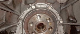
Generator rotor
The generator rotor with the sensor rotor located on it is mounted on the right axle axis of the engine crankshaft with a bolt and is secured against rotation by a key.
Caring for a sunrise motorcycle generator - how to remove, what to check and install correctly
Generator maintenance mainly comes down to tightening the threaded fasteners of the generator stator and rotor, as well as the wire terminals.
In order to remove the generator, you must:
- disconnect the wires of the ignition circuit, sensor, brake light and direction indicators from the generator terminals;
- unscrew the three screws securing the stator to the crankcase and remove the stator;
- Unscrew the bolt securing the generator rotor and, with light, careful blows of a wooden hammer on opposite sides of the rotor, remove it from the trunnion and remove the key.
Checking the removed parts
After removing the generator stator and rotor, wash the parts with clean gasoline and carefully inspect them. Disassemble the wire fastening terminals on the stator. Wipe dry all insulating parts of the terminals.
Generator installation
Installation is carried out in the reverse order, in this case it is necessary:
- check the runout of the generator rotor, which should be no more than 0.1 mm with the bolt secured;
- tighten the generator stator without distortions, ensuring a tight fit to all three supports;
- install the ignition correctly;
- The generator wires must be securely fastened and well insulated from each other.
Causes of malfunctions
The causes of malfunctions can largely be understood by how exactly the two-wheeled vehicle behaves. That is, what symptoms does the clutch assembly exhibit?
There are 2 options here:
- slip;
- incomplete inclusion.
If you notice that the clutch discs are slipping, there are several potential causes to consider:
- there is no free play at the lever responsible for turning off;
- the cable is stuck in the protective sheath;
- the grease has thickened or frozen due to cold weather;
- the discs are worn out, or the protrusions on some drive discs are deformed;
- the shutdown lever is stuck in the bracket;
- weakened operation of the clutch springs;
- The release worm is stuck on the right side of the crankcase cover.
For each situation, appropriate actions are provided to restore functionality.
If you notice incomplete engagement of the clutch system on your scooter, then the list of potential causes will be different. Here are some problems to consider:
- the shutdown mechanism has failed;
- the coupling is damaged;
- too much free play at the release lever;
- the oil turned out to be too thick, which is why the discs began to stick together;
- overheating caused the discs to warp;
- the length of the shutdown rod is worn out;
- The nut securing the driven drum has been unscrewed.
When faced with the fact that the clutch has begun to move, you should check the cable, as well as its sheath. Most often it becomes rusty, unraveled or bent. The cause may also be crooked discs and over-tightened adjusting nuts. But large free play at the lever should also not be ruled out.
In the case of clutch slipping, the list of reasons may be similar. Only here the adjusting nuts are not tightened enough, or the lever does not have free play.
Having studied the behavior of the Ant scooter, you can draw appropriate conclusions and begin troubleshooting work.
Ignition adjustment Voskhod
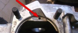
The ignition timing is set by turning the generator stator after first loosening the three screws securing the stator to the crankcase. For normal engine operation, it is necessary that the moment of spark formation (on the generator, this moment is determined by the coincidence of the sensor rotor groove with the protrusion on the sensor coil frame. Fig.) coincides with the moment when the piston does not reach the top dead center of 2.5-3.0 mm (at running the engine on gasoline with an octane rating of 92).
The gap between the rotor and the core of the sensor coil should be within 0.3±0.05mm.
The gap should be set as follows:
- loosen the screws securing the sensor stator to the generator stator cover;
- By moving the sensor stator in the grooves of the generator stator cover, set the required gap, and then tighten the fastening screws.
For more accurate ignition installation, it is recommended to determine the piston position with the cylinder head removed.
Clutch adjustment
Clutch adjustment parts are not located on any Soviet motorcycle, as they are on Voskhod. We unscrew the special plug in the center of the left crankcase cover. Inside we see an adjusting screw 1 with a locking nut 2. We insert a key onto the nut and loosen it. An important condition is to hold the nut with a wrench, only then insert a screwdriver into the bolt inside the wrench and start rotating. If this condition is not met, it is not possible to adjust correctly. Because if you don’t hold the nut or bolt and rotate one, they still rotate together, which leads to misadjustment.
We tighten the adjusting screw inward until we feel the stop against the fungus. Then use a screwdriver to unscrew the screw a quarter or half a turn back. So that the screw does not touch the fungus, we hold the screw in this position with a screwdriver. And only then we lock the screw and tighten the nut tightly to secure it.
All the main work is completed, all that remains is to install the recommended free gap of 5 - 10 mm on the control lever. This is done using a special bolt on the lever itself.
The long-awaited exciting moment. We start the motorcycle, warm it up and check our work. We move off smoothly. We sharply increase the engine speed. We give a load to the engine. Switching speeds. We brake and stop. If you don’t like something, you can repeat the adjustment and achieve the optimal clearance.
It’s impossible to do everything perfectly the first time, unless you’re lucky.
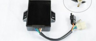
Switch Voskhod – electronic KET-1
The electronic switch KET-1 is designed to work in the ignition system complete with the G-427 generator and the B-300B high-voltage transformer. Allows you to obtain a secondary voltage of up to 18 kV, at a generator rotor speed of 250 to 7500 rpm. The switch is installed in the right toolbox. The base of the commutator is connected to the ground of the motorcycle. If the switch fails, it can be disassembled and repaired
The electronic switch has three output terminals with letter markings on the body >, > and >. The ground terminal is the base of the switch.
Maintaining the switch during operation comes down mainly to tightening the threaded connections, while avoiding stripping the threads. It is necessary to protect the switch from moisture getting inside it and onto the terminals from sudden shocks and exposure to high temperatures. You should also systematically check the reliability of the electrical connection of the switch base with >, because If this condition is violated, sparking on the spark plug stops.
Transmission
During transmission repairs, the following work may be required:
- Adjusting the clutch, replacing its disc and bearing;
- Clutch drive repair;
- Replacement of gearbox bearings;
- Repair of switching module parts;
- Restoration or replacement of gearbox gears.
Most of them require high qualifications and are difficult to do at home. The exception is the repair and replacement of drive mechanisms. So, sometimes there is a need to restore the splines for the gearbox foot, replace the clutch cable or its jacket, or adjust the clutch. These works are carried out without disassembling the crankcase.
Repair and operation of the Voskhod motorcycle are closely interconnected due to the age of the model. However, with the proper approach to organizing and carrying out repairs, the motorcycle will remain your faithful friend and assistant for a long time.
Spark plug Voskhod - spark ignition type A-23
During operation, the spark plug must be periodically cleaned of carbon deposits and the gap between the electrodes must be adjusted, which should be within 0.6-0.7 mm, which is ensured by bending the outer electrode. To seal, a copper-asbestos gasket is placed between the spark plug and the cylinder head. To eliminate radio interference created by the ignition system, a shielded tip of type A-4 is placed on the spark plug.
Motorcycles.
The practical manual provides the design and technical data of light (without sidecar) motorcycles of domestic production, Czechoslovak JAVA and ChZ, as well as sports ones. Instructions are provided for their dismantling, assembly and repair of individual parts, information on running-in, operation and maintenance.
- Publisher: Tekhnika
- The year of publishing: 1984
- Pages: 98
- Format: DjVu
- Size: 2.6 Mb
Discounts from the help desk
When you mention ACC you can get discounts on parts and services
- Add a company
- Registration
- Entrance
- 8
Automotive Help Desk: auto news, spare parts in Krasnoyarsk for foreign and domestic cars, disassembled cars, car repairs, addresses and phone numbers of companies, bulletin boards, spare parts catalogues, service and repair manuals.
All information presented on the site is for informational purposes only and under no circumstances constitutes a public offer.
Ignition switch Voskhod - central switch
Switch 124005490201 is used as a central software switch that provides the necessary switching of lighting equipment on a motorcycle. The switch has three operating positions >, >, > in accordance with the following operating modes:
- in position > – the generator sensor circuit is shorted to ground, which ensures the engine stops.
- in position > (driving during the day) – the ignition circuit is turned on, the direction indicator circuit operates (when the direction indicator switch is on) and the brake signal circuit (when the brake pedal is pressed);
- in position > (driving at night), two circuits are switched on:
- a) a circuit of speedometer backlight lamps, license plate lighting and city driving (through a throttle, which serves as a device that complements the parametric control of the generator);
- b) headlight lamp circuit A6-32+32 (via the light switch on the steering wheel).
In what cases is it necessary to adjust the clutch of a Voskhod motorcycle.
The engine was completely disassembled for a major overhaul. During which the worn coupling parts were replaced. In our case, slave and master disks. The springs that compress the discs were replaced if they were stretched out or damaged. The clutch drum has been replaced. The thread on a bolt or nut is broken; the purpose of these parts is adjustment. If the speedometer gearbox with the clutch release mechanism has been replaced or repaired.
In the photo: 1 – adjusting screw; 2 – fixing nut.
When riding the motorcycle under load, such as on a steep hill. Engine speed increases and speed decreases. The clutch is slipping
.
In the opposite case, we squeeze the lever, we want to disengage the clutch and stop, but this does not happen. The motorcycle does not obey and continues to move. Clutch leads
.
Switch P-200
Light switch with horn button (located on the left side of the steering wheel). To switch the low and high beam circuit, a P-200 type switch is used with a built-in push-button horn switch for three operating positions: neutral - the headlight lamp is off; far right – low beam is on; far left – high beam is on.
The horn button has a movable contact connected to ground and a fixed contact connected to one of the wires coming from the horn terminal. When you press the button, the contacts close and the signal circuit is completed.
How to adjust the clutch
Now to the question of adjusting the clutch assembly on Ant scooters. Here you will need to properly tighten the nuts. Typically, such a need arises if the scooter, or rather its clutch, is leading, and this makes the Ant unable to move on the roads normally.
The clutch release lever should have free play when the unit is in normal condition. If this free play is absent, then the clutch begins to slip. And when the stroke is too large, then the clutch does not engage completely. Both situations are a problem.
Therefore, you need to perform a clutch adjustment procedure. The procedure is performed according to the following recommendations:
- for a lever, the normal free play is in the range from 5 to 10 mm;
- to adjust the clutch, you must completely tighten the adjusting screw of the clutch cable;
- then, using a socket wrench, loosen the locknut of the adjustment screw, which is located on the crankcase;
- then tighten the screw until it comes into contact with the fungus;
- now you need to unscrew the adjustment screw a quarter of a turn and also secure it to prevent rotation;
- All that remains is to adjust the tension of the clutch release cable on the steering wheel of the Ant scooter.
After tightening the nuts, you need to press the lever and watch how the pressure plate moves away.
There are several additional recommendations in this regard.
- If the disk comes off, but does so skewed, then the corresponding nut will need to be tightened about half a turn. Then check that the settings are correct again.
- If half a turn was not enough, then make the same number of turns. Do this until the disc begins to move away optimally and evenly from the surface.
- In situations where the Ant scooter is used to transport a heavy load, the clutch may simply not be able to cope with such a load. In this situation, you usually have to deal with the slippage by turning the adjusting nut a few times.
- When the force on the lever seems too great, and the Ant is not used for cargo transportation, then the nut can be loosened to a comfortable level.
Electrical circuit of the Voskhod motorcycle
Central switch. 2. speedometer. 3. Speedometer light. 4. Headlight. 5. Headlight lamp. 6. City driving lamp. 7. Sound signal. 8. Direction indicator lamp. 9. Direction indicators. 10. Direction indicator switch. 11. Electronic switch. (D – sensor terminal, K – ignition coil terminal, G – generator terminal.) 12. Throttle. 13. Relay breaker. 14. Generator. 15. License plate lamp. 16. Brake signal lamp. 17. Rear light. 18. Wire connection block. 19. Brake light switch. 20. Shielded spark plug cap. 21. Spark plug. 22. High voltage wire. 23. Ignition coil. 24. Light switch.
Wire colors: sn. – blue, cf. – grey, g. – blue, g. – yellow, h. – green, k. – red, kor. – brown, op. – orange, f. – violet, h. – black.
Motoblog
A little bit about everything
Since VK complains about the size of the page being created, we have to resort to using LiveJournal again. So, let's say you bought an old Voskhod. According to the seller, it starts and drives (we will not consider options when the motorcycle is faulty and needs serious repairs in this material). How to assess his condition? How to understand what needs repair and what is “still fit”? Excellent material from the book by V. S. Zakharin and G. A. Pilyukevich “Motor tourism: sports and recreation” will help with this (you can download the book in the group’s documents. Read online here). I took the liberty of slightly redoing and adding to the original text, since it still talks about some general things, and we are interested in a specific brand of motorcycle. The original text is about preparing the motorcycle for long trips, so don't be surprised by some of the wording. But before you start studying the material below, download and read the motorcycle instruction manual - now it is your bible. You can download the instructions for your modification of the Voskhod motorcycle in the same place as the book from which the article was taken.
“It is advisable to adhere to the following sequence of motorcycle inspection: engine, electrical equipment, power system, brakes, chassis, tires, general fasteners. When examining, try not to miss the little things. Engine
. The engine of your motorcycle starts well, runs steadily in all modes, has good compression, you don’t hear any extraneous knocks, and it doesn’t smoke excessively. This means there will be little work. First, remove the cylinder head and cylinder. Let's check the radial clearance in the bearing of the lower end of the connecting rod. The limit value is considered to be 0.25-0.3 mm. Note; does the connecting rod stem touch the surface of the crankshaft cheeks? Radial play in the connecting rod upper head assembly should not be felt by hand. Only rocking of the piston without audible clicks is permissible. The piston must have uniform traces of running-in and carbon deposits on the right and left sides, i.e. in the plane of the piston pin, traces of carbon deposits on the side surface of the piston can only be in the area of the rings. If they are lower, then it is necessary to find out why the piston rings do not function well as seals. It is possible that some of their sections have “buried”, that is, they have lost mobility in the piston groove. Such a ring must be carefully removed, gradually rocking it, and the groove must be thoroughly cleaned. The best way to do this is with a piece of the piston ring. Just make sure that it doesn’t turn out to be the one you removed.
Carbon marks below the rings, located on one side of the piston, may also indicate the presence of a misalignment in the cylinder. To verify this, you need to remove the rings, install the cylinder, press it to the surface of the crankcase using bushings (the internal diameter is slightly larger than that of the stud, and the length is approximately equal to the height of the cylinder head bosses) and nuts. Rotate the crankshaft several times. Set the piston to top dead center and, pressing your finger at an angle on the bottom of the piston, press it against one side of the cylinder in the plane of the piston pin. If there is no misalignment, the piston will remain in its occupied position after removing the pin from its bottom. If there is a misalignment, it will spontaneously return to its original position as soon as you remove your finger. Repeat this operation, pressing the piston against the opposite side of the cylinder. Identifying the causes of the malfunction will require a thorough inspection of the crankcase, cylinder, and piston, and the distortion can be eliminated by straightening the connecting rod, installing gaskets under the cylinder, and adjusting parts. Unfortunately, we cannot describe this work in a similar way, because our article has a different purpose. Having installed the piston ring in the lower, less worn part of the cylinder, where there are no windows, we will check the size of the gap in the ring lock. For a new engine it is usually set within 0.2-0.4 mm. If the gap approaches 2-3 mm, then it is usually recommended to replace the ring. This, in our opinion, does little to increase engine power, since the new ring will not be able to get used to the worn surface of the cylinder, which has acquired a complex shape, for a long time. How to be? If the piston ring has reached the limit of wear, then the cylinder probably needs repair. Move the ring to the top of the cylinder, 0.5-1 mm short of the ring mark (the so-called “step”) at top dead center. Measure the gap in the ring lock, subtract the value of the previously measured (below) gap and divide the difference by 3.14. Obtain the cylinder wear value. If it is more than 0.25 mm, then it makes sense to start boring and honing it or buy a new one. You can read about boring at home here. It is necessary to check the amount of radial play in the main bearings of the crankshaft (especially in the right one), since it greatly affects the operation of the ignition system, which has a breaker (if the ignition is contact). Typically, the limit is considered to be a backlash of up to 0.06 mm (in new bearings the backlash is 0.008-0.022 mm). Also, if there is noticeable play, the tightness of the oil seal through which the engine will suck in air will be compromised, which greatly affects the stability of the engine. If you are in doubt about the tightness of the crank chamber, fill it with diesel fuel or fuel mixture from the motorcycle tank and note the level. A significant decrease in the level after a few hours will indicate a leak, and oil traces on the outside of the oil seal or gasket will indicate its place. The right oil seal and main bearing can be replaced without completely disassembling the engine. A gasket leak can sometimes be fixed by thoroughly degreasing the area, lubricating it with epoxy glue or sealant, and carefully tightening the mounting screws. On parts such as crankcase halves or covers, tightening begins from the middle of the part, tightening the screws located crosswise, and gradually moving to more distant ones. It is best to tighten it in several stages, gradually increasing its torque. But if possible, it is better to replace the gasket. Now reassemble the disassembled components, lubricating the rubbing surfaces with engine oil. Before assembly, do not forget to clean the exhaust ports, the piston crown and the surface of the combustion chamber in the cylinder head from carbon deposits. Clutch
.
Check the condition of the clutch discs. If there is significant wear on the lateral friction surfaces (cork, plastic), protrusions, or the absence of one of the protrusions, replace the discs. If in the grooves of the drive drum there is wear from the disc protrusions with a depth of more than 0.1 mm (the so-called “saw”), level their surface using a flat file. This operation is not easy and requires painstaking work. Here it is necessary to ensure that the clutch disc, after alignment, is adjacent to the grooves of the drum with all its protrusions at the same time, otherwise uneven distribution of the load can lead to breakage of the protrusions and breakage of the clutch. Therefore, if possible, it is better to replace such a clutch drum with a serviceable one. Carefully adjust and lubricate the clutch drive. With the clutch disengaged, check whether the pressure plate is distorted. Motor transmission
.
Check the condition of the teeth of the drive and driven chain sprockets and the condition of the chain. When the lower branch of the chain is tense, the sagging of the upper branch should not exceed 20 mm. This is checked using a rod attached to the top branch and a ruler. By the presence of wear on the end surfaces of the sprockets, one can judge that the sprockets are not in the same plane. Using washers or other measures, try to install them correctly. Transmission
. If the gears are switched with great effort or sometimes switch off on their own, you cannot drive. Since it is in this component of motorcycle engines that there are the greatest differences, our recommendations can only be of a very general nature. Engines in which the clutch “leads”, the latch sticks, or the gears move tightly along the shafts require a lot of effort when changing gears. Self-disengagement of gears occurs when the cams are not fully engaged or if their edges are chipped or “licked”. The complete engagement of the cams is usually adjusted by installing washers under the stops of the gearbox shaft bearings (under the retaining rings or covers). You can read about gearbox adjustment here. With any design, it is necessary to leave room for axial movement of the shaft of 0.1-0.2 mm. Usually the biggest trouble is caused by the self-switching of fourth gear. In this case, remove the secondary shaft sprocket, spacer sleeve, and oil seal and push the outer bearing race inside the gearbox. The freed space is filled with adjusting washers. Gears with worn cam edges are best replaced. Sometimes the shape of the cams is straightened using a cutting stone so that the side (working) surface forms an angle of 3–5° with the end of the gear.
Engine
The “heart” of a motorcycle, even with the most careful use, gradually wears out - this is facilitated by the abundance of heterogeneous mechanical loads in the cylinder-piston group and other moving parts, temperature effects on the metal, the chemical composition of the working mixture and exhaust gases. DIY motorcycle repair Voskhod most often includes the following engine work:
- removing the power unit from the motorcycle frame;
- partial or complete disassembly of the internal combustion engine;
- replacing piston rings;
- restoration of the cylinder mirror;
- repair or replacement of the piston, connecting rod, crankshaft;
- replacement of support bearings, liners, seals;
- lubrication, fastening, adjustment work.
Engine repair, like the repair of other units, must be preceded by a comprehensive diagnosis of its technical condition, which includes an analysis of operational parameters (approximate indicators of developed power and speed, fuel consumption, sound of operation, color and character of the exhaust). If necessary, diagnostics are performed on the bench, and specialized instrumentation is used.
It is important to navigate the structure of a two-stroke internal combustion engine of a motorcycle and understand how each specific type of repair is performed. So, when replacing piston rings, you can do without removing the engine. It is enough to unscrew the stud nuts, remove the cylinder cover and, opening access to the piston, bring the piston to top dead center. Then the worn rings are removed and new ones are installed. The engine is assembled, not forgetting to replace the gasket. This completes the repair.
Much more complicated is the process of replacing the crankshaft bearings and its seals, the need for which, especially if the motorcycle is used incorrectly, arises quite often. You will need to disconnect and remove the internal combustion engine, clean its external surfaces, disassemble the crankcase, allowing access to the crankshaft, and dismantle the latter. It is important to be careful when knocking out old bearings - if they become distorted, they can damage the seat. And, no matter how trivial it may sound, do not forget to remove the retaining rings. Then the new bearings are carefully pressed in, the crankshaft is installed on the left side of the pan and the engine is turned over. A pin is put on the nuts and the assembled module is screwed into the studs. The power unit is assembled in the reverse order. In case of wear of the inner surface (mirror) of the cylinders, they are bored to repair size and ground. This is a complex and highly precise job that must be carried out by experienced professionals and using special equipment. However, preliminary work - removing and disassembling the internal combustion engine - can be done independently. After the repair, you will have to replace the piston with rings with parts from the corresponding repair group.