Many of our compatriots dream of such a vehicle as an ATV. This hybrid of a tractor and a motorcycle combines their best qualities. It is used for driving over rough terrain, trips to nature or picnics, fishing, etc. The all-terrain vehicle is also actively used when performing various household tasks. An ATV is a fairly expensive vehicle, so many people decide to assemble it themselves. To do this, you will need to prepare the appropriate equipment and components. One of the popular options is to assemble an ATV from Oka with your own hands.
Many of our compatriots have an old but working car gathering dust in their garage. Oka is ideal for assembling an ATV. To do this, you will have to spend a certain amount of time and purchase the necessary parts. You will also need a welding machine and grinder, a set of keys, screwdrivers, and other hand tools. This is an exciting process during which the master will acquire new skills. If desired, a specialist will be able to assemble a homemade ATV from Oka with all-wheel drive.
At the initial stage, a drawing of the future vehicle is developed. You can use a ready-made scheme, but it is much more effective to create your own. When developing drawings for an ATV from Oka, you need to take into account that most of the parts can be removed from the old car.
Advantages of an ATV from Oka
An all-terrain vehicle assembled from Oka parts has many advantages over factory-produced models. One of the positive qualities is the efficiency of such an ATV. Since most of the parts will be taken from the donor vehicle, no significant financial investment will be required. If you have to buy additional parts, you only need a very small amount of them.
The weight of the ATV will be relatively light when compared with factory-produced all-terrain vehicle models, but the power will be significantly higher. The Oka has a two-cylinder liquid-cooled engine. For a car this may not be such a high figure, but for an ATV it is more than enough.
In this case, you can make your own 4x4 ATV with an Oka engine. The all-wheel drive all-terrain vehicle will be functional as well as versatile. It will be able to overcome significant obstacles on the road, cultivate gardens and vegetable gardens, and transport significant loads.
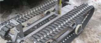
Frame assembly
To make an ATV from Oka, you must first make a base. You should work in a heated room with good ventilation or outdoors under a canopy. At the first stage, you need to assemble a frame, which is created by welding from the following parts:
- The lower and upper spars are made of two pipes with a round cross-section. The metal thickness should be 3 mm, and the cross-section diameter should be 25 mm.
- Auxiliary spars, which are used for struts.
- The spars are bent, which form the upper and lower planes.
- Clamps for shock absorbers and levers.
To install various components on the frame, you need to purchase the appropriate number of metal brackets and other small parts.
4x4 ATV based on OKI
An all-wheel drive ATV that is designed specifically for off-road driving. The design uses components and assemblies from a great variety of equipment - from OKI to Mitsubishi.
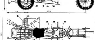
A little about the ATV itself:
- width 1550
- base 1600
- handlebar height 1300, saddle height 900
- ground clearance 430
- weight ~ 400 kg
- OKA engine
- gearboxes on axles - Mitsubishi RVR
- hubs and fists front and rear — Niva
- drive - Niva + 2108
- Suspension front and rear - A-shaped double wishbones
- elastic elements in the front - torsion bars, in the rear - springs
- power steering - converted from Subaru
- center differential locked
- The rear cross-axle differential is locked
Well, now the history of the construction, the story will be told on behalf of the author - Chatlanin . It should be noted that the device is constantly being improved and modified.
05 Feb 2009 yes, things are progressing little by little... it’s a pity that all the construction takes place in the evenings after work and for 3-4 hours. I’m waiting for some turning orders, a lot of things are slowing down, I gave the order to a turner from my old place of work, and this is the other end of Moscow. I moved to a new place of work, now I’m looking for turners and other necessary people nearby.
Front view
07 Feb 2009 pipe Ф21х4. If you weld a lever with diagonal spacers-amplifiers, do you think it will be rather weak? Yesterday I stopped by the MS store in Ochakovo, measured (my aunt measured) the pipe for the silent blocks - says F32...bought...the car broke down a little, then stood waiting for the person and then decided to measure it myself, fortunately there was a rod. In general, it turned out to be an internal F35, where does it go for me? I brought it back to the store and gave it away. I don’t know how she measured it there, or if she measured it with burrs...that’s how it burst. You'll have to go to the market. Buying at a metal depot will take half a day...
08 Feb 2009 I went around a bunch of markets today looking for an internal F32 pipe. And everywhere it’s the same, only at 35…. Damn, because of a meter-long piece of pipe, I drag myself to the metal depot and stand in queues....uuuuu
08 Feb 2009 2 per lever, 4 levers in the suspension... a total of 16 pieces. Tomorrow, if I can get away from work, I’ll try to drop by M.S. in Karacharovo, maybe there will be the necessary pipe (it seems to be in the catalogues). Another guy at the market said - go to the Gazprom metal warehouse. There they sell pipes for gas, seamless and thick-walled... but where is this hard-to-finish base (he said that there are only two of them in Moscow, and where not...). Well, or I'll go to a turner. About the turners, damn it... last Friday I gave a drawing of the adapter okashrus-flange of the Mitsubishi RVR gearbox... this Friday I dropped by to find out how things were going... the guys said, bring the grenades, we’ll do everything and weld it, and center it, and balance it... damn driveshafts. They say we won’t make a mistake...
15 Feb 2009 Under the right hand. Voros is interesting, but the speeds are not that high, max 50km in 4th. Moreover, I will be able to move away from the third without any problems (two gearboxes - one in the gearbox, the second on the wheels). I think that special jerking of the gearshift knob is not required, but playing with the clutch... squeezed the clutch, stopped, turned off the speed... the first two will actually turn out to be like tractors... Well, in general, this is still an open question and I’ll be honest, I haven’t fully worked it out yet, when it comes to this... then I’ll split hairs... On Friday evening I assembled the first suspension arm... Tomorrow, if I don’t forget, I’ll take the camera to work...
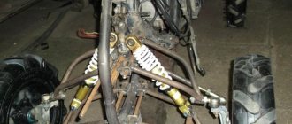
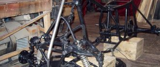
27 Feb 2009 The system works like this: We have a standard steering wheel - gearbox, rods... steering shaft and steering wheel. We take the steering rack, I took it from Toyota for analysis. More precisely, not the rack, but the hydraulic distributor from it (the rack with the steering wheel), which can be removed as a collapsible rack), we grind the gear, which turns the rack itself... and puts a cardan or something else there, depending on who you like. We put this crap in the section of the steering shaft, I have it as a cardan for the gearbox. Moreover, the connection remains 100% rigid, just like the standard shaft. It’s already clear about the power steering pump... Next, we put on the steering rod or, as I did for myself, I welded another ear to the bipod...a hydraulic cylinder. One side to the frame, the other to the rod. I won’t write about the hassle of measuring the working length, it’s different for everyone... in general, this scheme is often used on trucks, GAZ 66 for example. Even on the Volga 3110, the first Gurs did this. By the way, I installed the hydraulic cylinder from it, it costs 300 rubles. This design is good because the money costs: 1500 rubles for a rack (you can also attach a Volgov distributor - it also costs 300 rubles, but you’ll have to look for it), 500 rubles for a pump, 300 rubles for a hydraulic cylinder, two hoses for 200 rubles each and + turning work - adapters for fittings 2-3 more 200 rubles. total about 3000 rubles. A standard UAZ one costs from 12,000 rubles. At the same time, we have a hydraulic booster without changing the design of the standard system, an awesome steering damper (which is very important for off-road driving with large rollers), a fairly reliable unit, if it fails, for further movement it is enough to remove the belt from the pump (so as not to burn the pump), or drain the oil... There is a lot written about this gur on the UAZbook. So you can implement such a scheme by shortening the cylinder to the required size, for compactness and so that the liquid has time to fill it when turning the steering wheel (the steering wheel will be of a motorcycle type)…. but before that it’s still…build and build…. This is what I have configured for today... I have completed the front suspension. All that remains is to attach the elastic elements such as the stand.... I adjusted the frame a little... the maximum travel to the top... the total turned out to be 290mm, the ground clearance at the maximum to the bottom is 450mm - on standard UAZ wheels
On April 13, 2009 I purchased Ural springs assembled with shock absorbers. I installed 1 piece per wheel on the front axle. As soon as I removed it from the trestles, the quad immediately fell to my “knees”, while the springs folded all the way. I put two on the wheel and they hold, but when I sit astride it and move my weight closer to the steering wheel, almost the same thing happens! What kind of crap is this? at the moment he cannot weigh more than 250 kg! Yes, the rear is still on the sawhorse, so maybe that’s why all the weight goes to the front. ….in the end I made a torsion bar front suspension. As torsion bars I used a stabilizer bar from the classics, altering it a little. One rod per wheel and arranged them lengthwise. I adjusted the suspension height and stiffness using a lever and a bolt (as on torsion bar suspensions) - it holds perfectly, the ride suits me too! I think the back can do the same. The question is, will they burst? the welding site is heated to red hot, i.e. welding has non-surface calcination…. tests will show. I'm waiting for the turner when the wheel drive shafts are ready. Photos later, when I get to work, or rather the workshop...
May 29, 2009 the front and rear suspensions are absolutely the same! Even in the rear suspension I used steering knuckles from the Niva. I took the Niva suspension drawings, analyzed them, calculated the length of the arms based on the drawing.....and built my own. parts of the front and rear suspensions are maximally unified and interchangeable. On the rear suspension, the toe-in is adjusted by the steering rod, it is attached to the frame. You can turn on the steering, it’s like a third lever... the camber - I adjusted it with my ears - using the silent block fasteners. The center of the drive and silents are located almost on the same straight line. The drive was measured locally. There are all sorts of messes and other things that can be done on the knee using welding and a grinder. Today I have finished the transmission and finishing the outer frame. I made a hydraulic clutch drive, instead of a cable like on an oka, it works perfectly and very smoothly. there is still a lot to do. But it's already on wheels.
May 29, 2009 the front and rear suspensions are absolutely the same! Even in the rear suspension I used steering knuckles from the Niva. I took the Niva suspension drawings, analyzed them, calculated the length of the arms based on the drawing.....and built my own. parts of the front and rear suspensions are maximally unified and interchangeable. On the rear suspension, the toe-in is adjusted by the steering rod, it is attached to the frame. You can turn on the steering, it’s like a third lever... the camber - I adjusted it with my ears - using the silent block fasteners. The center of the drive and silents are located almost on the same straight line. The drive was measured locally. There are all sorts of messes and other things that can be done on the knee using welding and a grinder. Today I have finished the transmission and finishing the outer frame. I made a hydraulic clutch drive, instead of a cable like on an oka, it works perfectly and very smoothly. there is still a lot to do. But it's already on wheels.
July 23, 2009
I tested my little animal today. rushing like a tank... I even managed to push it a little :-))) I need to figure out something with the brakes, the pedal is a little hard to press. But in general everything is fine. The suspension works and goes over bumps well. It takes a little getting used to the hydraulic fluid. I welded the box (differ) for nothing. The LSD in the bridge works like crap - I’ll put it forward, and the front one in the rear and turn on the navigation. I'll post the photos later...
19 Aug 2009 The first trial start was back in early July. The motor works great. Back then, the differential was not blocked in the box, and when accelerating hard, the quadric jerked and squealed with UAZ tires... it was scary... Then they welded the differential, and the jerking stopped. I even managed to get him caught in a pile of stones and sand - I didn’t want to go forward anymore, only back. The rear locking was not enough... and the front one too... Yesterday I swapped the gearbox - put it in front with LSD (since it is of little use), and in the rear with the front one (having first welded the differential). I have them interchangeable (the same). In almost all dimensions it is similar to the Yamaha Reno, but I have less weight and larger wheels... and the ground clearance, respectively, at full stroke of the levers down (max stroke down) is 420mm. The base is 1600, the width at the edges of the wheels is 1300, the height of the handlebar is 1300, the height of the saddle is 900. The total length of the body is 2200. The quinoa, which without a block has a stated lifting capacity of 250 kg, although it is heavy, lifts it off the ground. The weight is somewhere around 350 kg. This is so offhand. The wheels are very heavy - 80-100 kg. Here are some more photos from today...also from a cell phone. The camera is a long way to go, and I always forget about it... I’m mastering fiberglass, so to speak.. There are literally 1-2 layers of glass fabric, so the cardboard frame-backing (back part) is visible through.
20 Aug 2009 I think the maximum speed will not be more than 60... but I don’t really need that much. The gears are switched manually, everything works smoothly, I'll take a photo later. Gearboxes cost 3000 and 5000 with LSD - but it’s crap, it almost doesn’t work - only for snow... The assembled drives cost 1500+ NIVSKIE EXTERNAL GRENADES AND sticks + threading on the sticks and a sleeve-nut connector... in general, each drive cost about 2000 rubles. The most expensive spare parts are - everything else is small stuff. Gearbox from Mitsubishi RVR. A small axle shaft is inserted into the gearbox, and a drive is screwed to it with 3 bolts - it is very convenient to remove the drive! Brake without vacuum. Made from a clutch master cylinder and two Niva calipers. On the calipers, I combined the cylinders under one hose (in the field they work separately) now on the Chevrolet. The brakes are currently only on the rear axle, but the front axle is also braked through the transmission. Hydraulic clutch, consists of classic GCS and RCS. It is activated by the pedal on the left (temporarily removed for fiddling with fiberglass, but there is a desire to make it on the steering wheel). I haven't driven with a welded diff yet. But I rode a Merc Gelendvagen with 100% locks, rushing like a tank, but steering a little worse (it’s easier for the car to drive straight), but my front end is free. More precisely, it contains LSD, but it blocks it quite a bit. So everything should be fine! With fiberglass, the worst thing is the air! you need good fiberglass. I’ve run out of it, I’m left with it removed from the pipes (not stale) - it’s soaked in something, and it’s really lousy…. In general, something like this.....
11 Oct 2009 By weight, according to preliminary calculations, it turns out to be about 400 kg, and the heaviest thing is the wheels... the base is 1600, at the edges it was 1300, but now I installed different tires and it ended up being about 1400... At first speed it climbs into the wall, although it’s a bit heavy... but on the second one you can get underway and drive quite briskly... well, I haven’t had to turn on the third one yet - there’s nowhere to accelerate like that... I think maybe I can install a gearbox with higher numbers...
Oct 25, 2009 I primed it... Some small mistakes came out during the preparation... I'll touch it up and paint it.... Trying on evil tires. I had to widen the rims to 8″, and even then they were a little small - the tires were bent...
09 Nov 2009 A test drive over the weekend showed that the vehicle has decent cross-country ability - it walks almost freely through the swamp, where the UAZ truck on 35″ wheels hangs on the bridges... But the first jamb came out - the weak point was the power steering cylinder from the Volga 3110, the rod was bent and broken with a diameter of 10 mm... it needs to be thicker... I had to get to the gazelle without a hydroch - it’s quite difficult on these wheels. But you can go. In third gear, 4th, it became scary to engage; according to GPS data, a speed of 35 km/h was reached - on a forest road with a small rut….more is possible…. It drags 2 adult men without any problems, as does one, the only thing is that the rear suspension breaks a little on large bumps. It will be necessary to select other springs and increase the suspension travel... In general, the test drive was particularly unsuccessful - because... The technology quickly failed and the remaining shortcomings were not identified....it's a pity. I couldn’t drive it any further because... I didn’t take my original alternator belt to turn off the hydraulic system (otherwise it would burn out), in general, because of this and...that’s all..
14 Nov 2009 A power steering rack was taken. From the rack we take the distributor (spool assembly) and the hydraulic cylinder through passage. The cylinder is made impenetrable - it is welded on one side and the rod is cut accordingly... Initially, I took a cylinder from a Volga 3129-3110 gyroscope with a separate circuit (i.e. with a power cylinder). But during testing the rod could bend and it broke (the diameter of the rod was about 7 mm), although the UAZ carries 36″ wheels. It was bent due to the hinge being made incorrectly. The result was an undesirable lever that gave a skew - which is why it bent... On Wednesday I bought the cheapest rack at a disassembly from a right-handed Subaru, made a cylinder out of it. Rod diameter 21mm. I re-threaded the rod to M16x1 - for a classic steering end. I slightly modified the bipod, or rather the lever for attaching the cylinder to the bipod. I installed everything. Works great, no hints of bending... This is the original idea with the ball - it’s not vulgar because the ball has small stroke angles... I posted videos from tests... a little bit true... https://video.mail.ru/mail/ramm_stas/3/7.html https://video.mail.ru/mail/ramm_stas/3 /6.html
23 Nov 2009 A short report from tests No. 2. The device drives decently, even very decently. It rushes through the swamp and clay like a tank. Among the breakdowns, this time the rear-wheel drive turned out to be the weak point. At the beginning of the ride, the nasty stick pierced and tore the boot of the outer CV joint. After some time, the separator shattered... There was only one drive rear wheel left. But even at the same time, the quad is like a tank. In fact, we drove for another 4 hours along the entire off-road competition route. Then, in a ford with a fairly difficult exit, the drive shaft broke. A scrap piece from a Niva was pulled together, but the Mitsubishi was intact. And the connection is also normal. It looks like the Niva pieces of iron cannot withstand the loads. But we drove along the highway together, which probably gave such a result. It rides on the front end, but is unsure and mostly skids. This week I will dismantle the suspension and change the hardware to the same ones. I'll see if it's overload... Otherwise, maybe I’ll have to do it on cardans…. A little video https://video.mail.ru/mail/ramm_stas/3/8.html https://video.mail.ru/mail/ramm_stas/3/9.html https://video.mail.ru/ mail/ramm_stas/3/10.html https://video.mail.ru/mail/ramm_stas/3/11.html Yes, we need to make wing flares, otherwise there will be a mud shower..., although chemical protection copes with this quite well :- ))
09 Dec 2009 With a gear ratio of 27? Then it won’t work - the tires are very heavy - the assembled wheel weighs 40kg - HORROR!!! Last week I sold these wheels, and today I finally picked up another 28x12xR14 tire from a quad - the weight is 3 times less, with a larger width and the same lugs and a total weight of 20 kg. Volgov 14″ wheels boiled down to 9″ wide…. As soon as I collect a photo, I'll post it. I also dismantled the rear suspension - I’m making adjustable struts based on Okovsky springs and shock absorbers (they will be like replaceable cartridges in the struts), the Ural struts break through and are very rigid...
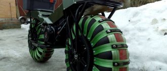
18 Dec 2009 I’ve slightly redesigned the rear suspension, or rather the elastic elements... now with adjustable stiffness and replaceable shock absorbers. Reduced the weight of the wheel by 2.5 times - by replacing the wheels..., tires from a quadric 28x12xR14 Volgov disk, welded to 9″. True, the width has changed to 1550mm , although it is more stable now. I rebuilt the gas truck and replaced the motorcycle with a quad trigger. It is more effective and convenient in shitting - proven! The device has become noticeably faster and more powerful. The suspension travel and smooth operation have increased significantly. All that remains is to carry out a “combat” sortie and test everything under harsh conditions... a few photos (from a mobile phone)
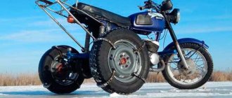
10 Jan 2010 I drove it almost all weekend. The flight is normal, it rushes confidently through 30 cm of snow. The rear spring burst (the front spring) - I replaced it with the front ones, but they turned out to be too soft. it needs to be tougher... Here's a little video.. https://www.youtube.com/watch?v=ETxWlFMGGho January 10, 2010 gear 2 and a little on the third. I tried 4th on the asphalt - I easily caught up with the motorcycle (it was traveling 40 km, according to him) and overtook it - 60 I think it’s going. The asphalt is a little slippery because of the snow, it started to drive faster... And in the forest we received nagany from skiers. Druzhban on a motorcycle is mainly on the ski track in the left lane (on virgin soil it’s a little hard), and I’m close or in the cut... Our ski track is wider than theirs - so they were offended .
31 Jan 2010 minor improvements to the rear suspension... Well, I finally waited for the tokor, which has been composting my brain for 3 weeks... people don’t want to work for money, but at the same time they complain that there is no money... Yesterday we made all the necessary hardware... I took cups for the springs from the rear shock absorbers 2108 (I had to climb through piles of iron in scrap metal receptacles), in order to get the best fit for the spring, saving weight and money. I shortened and lengthened the supports accordingly, as recommended. Let's see how it works. VZL springs with variable pitch from 2108 - they are easy to cut, and the part of the spring with a frequent pitch is the softest and will fit perfectly into all structures. The weight of the finished structure was 5.5 kg. This is what I did...
09 June 2010 Here are some new videos, although it was back in April, but they only just reached me... Test drive in a swamp shithole..... Broke an ice floe and hung on it..... https://www.youtube.com/ user/MarkowskiyStanislav#p/a/u/2/iM1cxb9V190 https://www.youtube.com/user/MarkowskiyStanislav#p/a/u/1/WcS6CUBN-K4 https://www.youtube.com/user/ MarkowskiyStanislav#p/a/u/0/Ym5IxHTyIqY
Finalization of the design
After assembling the frame, you should take care of the transmission, which will be unique in this system. Despite the fact that the engine is all-wheel drive, there is no gearbox in the system. In this case, the engine is installed lengthwise, which allows you to change gears and synchronize the transmission with the output shafts. If in the Oka the right and left wheels worked together, then in the ATV it is necessary to create a different type of drive. Two front and two rear wheels will work synchronously. Such modification is necessary in order to provide the all-terrain vehicle with the appropriate performance characteristics for driving on hard off-road conditions.
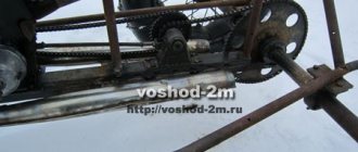
The technician needs to move the units on the frame to the left, since the horizontal unit of the transmission shafts will decrease. Otherwise, the system will not function correctly. The Oka gearbox needs appropriate modifications. A gear pair is removed from it, instead of which a chain drive will be installed. This will balance the speed and also increase torque at the same time.
The gear shift needs to be lengthened and the gear shift lever installed on the left. There are 4 gears in this design: two in front and two in rear. As the system operates, the speed position of the lever will change.
It is recommended to remove the gearboxes that are installed between the wheels. This is a characteristic feature of cars produced by VAZ. The axles are removed, like the stocking, and shafts designed for front-wheel drive vehicles are installed instead.
Rebuilding the transmission is the most difficult part of assembling an ATV system from an old vehicle.
DIY ATV frame drawings
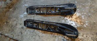
The false tank has a complex shape. It was not possible to bend it out of hardboard. Therefore, having wrapped the engine with plastic film, I began to fill the space intended for it with layers of polyurethane foam. After each layer, drying is mandatory, otherwise the thick volume of foam may not dry out inside. Filled until the layers went beyond the contour. Finally, after the foam had completely dried, I began to draw out the desired shape with a knife. The edges were smoothed with coarse sandpaper.
Part of the Oka dashboard was used under the instrument panel. I secured it to the blank also using polyurethane foam. Since the foam is large-porous, the pores were filled with gypsum and then processed. When the shape of the blank began to correspond to the intended design and its surface became more or less smooth, I coated the blank with PF-115 paint. Since I was not going to make a matrix for gluing the body kit on the block, but immediately glued the body kit on it, followed by finishing the surface to an ideal state, putting plaster and painting the block could be neglected.
So, the blockhead is ready and to glue a high-quality product, it was required: 10 kg of epoxy resin, 1 kg of plasticizer for it and 1 kg of hardener, 15 linear meters of thin fiberglass fabric, 5 m of glass mat, brushes, gloves. It is highly advisable to wear breathing protection. And the more expensive they are, the more reliable they are. But, as you know, you can’t buy experience, so I gained it in the process of work.
I used transparent tape as a separating layer between the block and the product. The whole idiot covered it with stripes carefully, without any omissions. It only took 1.5 rolls of wide tape.
I diluted the resin in 200 - 300 grams with a hardener and plasticizer. I used measuring cups and syringes, which is not very convenient. Before this, I cut strips of fiberglass in such sizes that large canvases would lie on flat surfaces, and on uneven surfaces, pieces of fabric could repeat them without making folds. By the way, fiberglass stretches moderately along the diagonal of the weaves, “flowing around” the desired shape.
First, I thickly coated one area of the blockhead with epoxy resin, placed fiberglass on it and impregnated the top with resin again. The adjacent piece of fabric was glued using the same technology with an overlap of 3 - 5 cm. We had to work quickly - the resin sets quite quickly, and the higher its temperature, the faster. Yes, I also heated the resin a little near a powerful lighting lamp for better fluidity.
Read also: Setting up the 2nd generation Lovato LPG gearbox
After covering the blockhead with fiberglass in one layer, I began to cover it with glass mat. The fiberglass mat I got was quite thick, and it turned out to be good for gaining the thickness of the product. But it does not hug uneven surfaces, so I used it only on flat (or slightly sloping) surfaces and without overlap. Impregnation with resin was carried out in the same way as when working with fiberglass. Just keep in mind that it takes a lot of resin to impregnate glass mat, so you need to dilute it more. After gluing the glass mat, uneven surfaces were glued in several layers with cloth. Each subsequent layer was applied after the previous one had set a little, so that the resin would not leak. And since the process of gluing the body kit took more than one day, after a day of break it was necessary to “roughen” the surface with coarse sandpaper and degrease it - after all, the resin cures completely during this time. The final layers on top of the mat were again covered with fiberglass, and not even just one layer.
Since I needed the surface, as they say, the smoother the better, and I didn’t have enough experience, dips and holes still remained - I filled them with resin alone, and with pieces of fiberglass applied there. There wasn't enough resin. I already bought more at the hardware store, in boxes. I liked working with it more because it was already packaged, and all I had to do was mix the ingredients. And it dried faster than the one purchased from the company.
After the glued body kit had completely dried, I made cuts in it, dividing the product into three parts: rear fenders and rear, false tank with seat, front fenders and front end. Carefully, slightly prying and pulling with his hands while picking, he separated the product piece by piece without much effort from the blockhead.
Now, having removed the parts, I began to process them separately, bringing them to the desired result. In general, ordinary preparatory and painting work using “all” technology: first, rough grinding with the removal of large bulges of resin and fiberglass; then painstakingly filling the recesses with putty and fiberglass; then grinding the outer surface and priming with a plasticizer. Finally - metallic painting and varnish with a plasticizer.
The blockhead also carefully cut it off and put it in the far corner - just in case. The body kit was attached to specially made and welded “in place” mounts on the frame.
Finally, I welded front and rear luggage racks from thin-walled steel pipes with an outer diameter of 20 mm, and in addition to them, “kangaroo bars” that replaced the bumpers.
Completing the build
The corresponding attachments, controls, and gas tank are installed on the frame. All elements are firmly fixed to the frame. The battery needs to be changed, buy the appropriate battery that is suitable for the ATV. Traveling in nature far from home is very important, since without high-quality power to the electrical system, the vehicle will not be able to move.
When all the components and mechanisms are installed, you need to trim the body with metal or plastic parts. The first option is preferable. They will be able to protect all components from damage, since the body of the ATV is often subject to impacts. The surface of the body is primed and painted. You can decorate it with stickers of standard or original designs. If necessary, you can print any image.
At the last stage, headlights, rear-view mirrors, trunk and other additional structural components are installed. After completion of the work, the functionality of the system is checked and modifications are made if necessary.
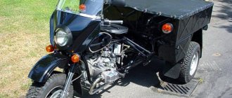
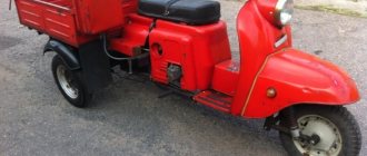
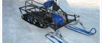
A homemade ATV is assembled not only from the Oka: read how you make your own ATV from the Ural, Ant, Dnepr, from a walk-behind tractor and a scooter.