Electrics and electrical equipment of a scooter
Dedicated to all owners of Chinese scooters...
First, I would like to present a wiring diagram for a Chinese scooter.
Since all Chinese scooters are very similar, like Siamese twins, their electrical circuits are practically no different.
The diagram was found on the Internet and is, in my opinion, one of the most successful, since it shows the color of the connecting conductors. This greatly simplifies the diagram and makes it more comfortable to read.
(Click on the image to enlarge. The image will open in a new window).
It is worth noting that in the electrical circuit of a scooter, just like in any electronic circuit, there is a common wire . On a scooter, the common wire is the minus ( - ). In the diagram, the common wire is shown in green . If you look more closely, you will notice that it is connected to all the electrical equipment of the scooter: headlight ( 16 ), turn relay ( 24 ), instrument panel backlight lamp ( 15 ), indicator lamps ( 20 , 36 , 22 , 17 ), tachometer ( 18 ), fuel level sensor ( 14 ), horn ( 31 ), tail light/brake light ( 13 ), start relay ( 10 ) and other devices.
First, let's go over the main elements of the Chinese scooter circuit.
Egnition lock.
Ignition switch ( 12 ) or “Main switch”. The ignition switch is nothing more than a regular multi-position switch. Even though the ignition switch has 3 positions, the electrical circuit uses only 2.
When the key is in the first position, the red and black wires are connected. In this case, the voltage from the battery enters the electric circuit of the scooter, the scooter is ready to start. The fuel level indicator, tachometer, sound signal, turn relay, and ignition circuit are also ready for operation. They are supplied with power from the battery.
If the ignition switch malfunctions, it can be safely replaced with some kind of switch like a toggle switch. The toggle switch must be powerful enough, because the entire electrical circuit of the scooter is, in fact, switched through the ignition switch. Of course, you can do without a toggle switch if you limit yourself to short-circuiting the red and black wires, as the heroes of Hollywood action films once did.
1 is shorted to the housing (common wire). In this case, engine operation is blocked . Some scooter models have an engine stop button ( 27 ) to block the engine, which, like the ignition switch, connects the white- black and green (common, body) wires.
Generator.
The generator ( 4 ) produces alternating electric current to power all current consumers and charge the battery ( 6 ).
There are 5 wires coming from the generator. One of them is connected to a common wire (frame). The alternating voltage is removed from the white wire and supplied to the relay regulator for subsequent straightening and stabilization. The yellow wire removes voltage, which is used to power the low/high beam lamp, which is installed in the front fairing of the scooter.
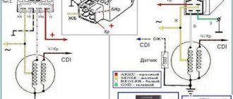
Also in the design of the generator there is a so-called hall sensor . It is not electrically connected to the generator and there are 2 wires coming from it: white- green and red - black . The hall sensor is connected to the CDI ignition module ( 1 ).
Relay regulator.
Regulator relay ( 5 ). People may call it a “stabilizer”, “transistor”, “regulator”, “voltage regulator” or simply “relay”. All these definitions refer to one piece of hardware. This is what the relay regulator looks like.
Read also: Is it possible to overtake through a solid road?
The relay regulator on Chinese scooters is installed in the front part under a plastic fairing. The relay-regulator itself is attached to the metal base of the scooter in order to reduce the heating of the relay radiator during operation. This is what the relay regulator looks like on a scooter.
In the operation of a scooter, the relay regulator plays a very important role. The task of the relay regulator is to convert the alternating voltage from the generator into direct voltage and limit it to 13.5 - 14.8 volts. This is the voltage required to charge the battery.
The diagram and photo show that there are 4 wires coming from the relay-regulator. Green is the common wire. We have already talked about it. Red is the output of positive DC voltage 13.5 -14.8 volts.
The regulator receives alternating voltage from the generator through the white wire to the relay. Also connected to the regulator is yellow wire coming from the generator. It supplies the regulator with alternating voltage from the generator. Due to the electronic circuit of the regulator, the voltage on this wire is converted into a pulsating one, and is supplied to powerful current consumers - the low and high beam lamps, as well as the dashboard backlight lamps (there may be several of them).
The supply voltage of the lamps is not stabilized, but is limited by the relay regulator at a certain level (about 12V), since at high speeds the alternating voltage supplied from the generator exceeds the permissible limit. I think those who have had their dimensions burned out due to malfunctions of the relay-regulator know this.
Despite all its importance, the device of the relay regulator is quite primitive. If you pick apart the compound with which the printed circuit board is filled, you will find that the main relay is an electronic circuit consisting of a thyristor BT151-650R , a diode bridge on 1N4007 , a powerful diode 1N5408 , as well as several wiring elements: electrolytic capacitors, low-power SMD transistors, resistors and a zener diode.
Due to its primitive circuitry, the relay-regulator often fails. Read about how to check the voltage regulator here.
Ignition circuit elements.
One of the most important electrical circuits in a scooter is the ignition circuit. It includes the CDI ignition module ( 1 ), ignition coil ( 2 ), spark plug ( 3 ).
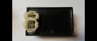
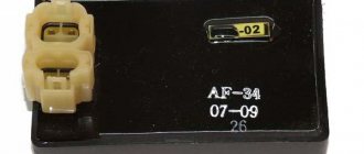
CDI ignition module.
The CDI ignition module ( 1 ) is made in the form of a small box filled with compound. This makes it difficult to disassemble the CDI unit if it malfunctions. Although the modular design of this unit simplifies the process of replacing it.
There are 5 wires connected to the CDI module. The CDI module itself is located in the bottom of the scooter body near the battery compartment and is secured to the frame with a rubber clamp. Access to the CDI block is made difficult by the fact that it is located in the bottom part and is covered with decorative plastic, which has to be completely removed.
Ignition coil.
Ignition coil ( 2 ). The ignition coil itself is located on the right side of the scooter and is mounted on the frame. It is a kind of plastic barrel with two connectors for connection and a high-voltage wire output that goes to the spark plug.
Structurally, the ignition coil is located next to the start relay. To protect against dust, dirt and accidental short circuits, the coil is covered with a rubber cover.
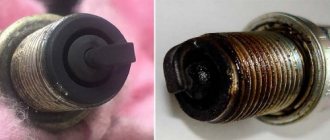
Spark plug.
A7TC spark plug ( 3 ).
The spark plug turned out to be cleverly hidden on the scooter, and it can take quite a long time to find it the first time. But if we “walk” along the high-voltage wire from the ignition coil, the wire will lead us straight to the spark plug cap.
Read also: Repair of Mercedes Vito 638 steering rack
The cap is removed from the candle with a little effort. It is fixed to the spark plug contact with an elastic metal latch.
It is worth noting that the high-voltage wire is connected to the cap without soldering. The insulated stranded wire is simply screwed onto the screw contact built into the cap. Therefore, you should not pull the wire too hard, otherwise you can pull the wire out of the cap. This can be easily fixed, but the wire will have to be shortened by 0.5 - 1 cm.
It's not so easy to get to the spark plug itself. To dismantle it, a socket wrench is required. With its help, the candle is simply unscrewed from its seat.
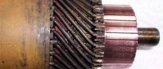
Starter.
Starter ( 8 ). The starter is used to start the engine. It is located in the middle part of the scooter next to the engine. It's not easy to get to.
The starting of the starter is controlled by the starting relay (10).
The start relay is located on the right side of the scooter frame. The starting relay receives a thick red wire from the positive terminal of the battery. This is how the start relay is energized.
Fuel gauge and indicator.
The fuel level sensor ( 14 ) is built into the fuel tank.
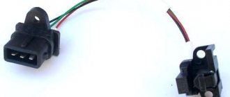
There are three wires coming from the sensor. Green is common (minus power), and the other two sensors are connected to the fuel level indicator ( 11 ), which is installed on the dashboard of the scooter.
The fuel sensor ( 14 ) and indicator ( 11 ) are one device and are powered by a constant stabilized voltage. Since these two devices are spaced apart, they are connected by a three-pin connector. The positive supply voltage is supplied to the fuel indicator and sensor via the black wire from the ignition switch.
If you open the three-pin connector coming from the fuel sensor, the fuel indicator will no longer show the fuel level in the tank. Therefore, if your fuel indicator does not work, then check the connecting connector between the sensor and the fuel indicator, and also make sure that they are receiving power.
It is also worth remembering that the supply voltage is supplied to the sensor and indicator when the ignition switch is in the closed position ( 12 ). According to the diagram, this is the right position.
Turns relay.
Turn relay or breaker relay ( 24 ). Serves to control the front and rear turn signal lamps.
As a rule, the turn relay is installed next to the instruments (speedometer, tachometer, fuel level indicator) on the dashboard. In order to see it you need to remove the decorative plastic. It looks like a small plastic barrel with three terminals. When the turn signals are on, it makes characteristic clicks with a frequency of about 1 Hz.
After the turn relay, a turn signal switch ( 23 ) is installed. This is an ordinary key switch that switches the positive voltage from the turn relays (gray wire) to the lamps. If you look at the diagram, when the switch is in the right position ( 23 ), we supply voltage through the blue wire to the right front ( 21 ) and right rear ( 32 ) indicator lamp. If the switch is in the left position, then the gray wire is shorted to the orange one, and we supply power to the left front ( 19 ) and left rear ( 33 ) indicator lamp. In addition, in parallel with the corresponding indicator lamps ( 19 , 20 , 32 , 33 ), signal lamps ( 20 and 22 ) are connected, which are located on the dashboard of the scooter and serve as a purely informational signal for the scooter driver.
Sound signal.
The sound signal ( 31 ) of the scooter is located under the plastic fairing of the scooter next to the relay regulator.
The audio signal supply voltage is constant. It comes from a relay regulator or battery (if the engine is turned off) through the ignition switch and the horn button ( 25).
Read also: Installation of the UAZ 417 distributor drive
Low/high beam lamp ( 16 ). Yes, the same one that lights our way in the dark.
The lamp itself is double with two filaments and three contacts for connection to an electrical circuit. One of the contacts, of course, is common. Lamp power 25W, supply voltage 12V. It burns shamelessly when the relay-regulator is faulty due to the fact that it does not limit the voltage amplitude at 12 volts, which leads to the fact that a voltage of 16 - 27 volts, or even more, is supplied to the lamp. It all depends on the speed.
Therefore, if at idle the lamp shines very brightly, and not at full intensity, then it is better to turn it off and check the relay regulator. If you leave everything as is, the low/high beam lamp will burn out, which is sad. Its cost is decent.
In the photo next to it is the turn signal lamp (red). Lamp power 5W for supply voltage 12V.
A light on a scooter is one thing that is not necessary, but without it it is very difficult. Especially at night without light it is a disaster. But if the headlight on a scooter doesn’t work, that’s one thing, but if neither the headlight nor the turn signals nor the brake light works, then that’s another matter. An emergency situation is created here, especially in the city. Today we will find out why the light on the scooter does not work.
And so, why the light on the scooter does not work. The light bypasses the voltage regulator , since it greatly reduces the output power. If the low beam, high beam and dimensions are missing, then you need to check the headlight-toggle switch-generator wiring. The problem may even be through the connector for the license plate light bulb. If the contacts do not fit well, it may short out. Check that the wires leading to the solenoid valve are not shorted.
If you ride a scooter without a battery , this can also lead to negative consequences and may result in the light on the scooter going out . This is due to the fact that the battery takes on voltage fluctuations. Therefore, without it, turn signals and signal may not work well. Or the headlight bulbs, brake lights, and turn signals completely burn out. This may cause the lights on the scooter to go out.
If you do not drive without a battery, then to find out why the lights on the scooter went out, you can use the wiring diagram:
When the light on the scooter goes out, you first need to check the wiring. Perhaps something has become disconnected or burned out somewhere. This will be visible immediately.
If only the headlight does not work, then you need to pay attention to the generator, wires, and connectors. And of course, check the light bulb itself and whether there is voltage going to it. a short circuit somewhere in the wires and they simply burned out. In this case, simply replacing these wires will help. The generator is responsible for the headlight . Check its functionality, it may be broken.
Thus, the reason that the light on your scooter has disappeared may be hidden in the above. By checking the details mentioned in the article, you will find the reason why there is no light on the scooter.
From time to time, questions arise with turn signal relays when LED lamps are installed in the turn signals on a motorcycle, and not only on motorcycles, but also on cars, or when the turn signals themselves are replaced entirely with LED ones. Standard relays, as a rule, refuse to work with such light bulbs because the load is too small. It (the relay) perceives the LED lamp as a broken wire and begins to switch faster than usual. Under normal conditions, this is convenient: the relay began to “click” faster than usual, which means that some light bulb has burned out. But for someone who has consciously replaced incandescent bulbs with LEDs, this is the beginning of a headache. Just a few years ago, electronic turn signal relays for LEDs cost about 500 rubles, which is not at all humane. Then I just needed a relay for the LEDs. After scouring the Internet, I found an article about converting a conventional automotive three-pin electronic turn signal relay into a relay for LEDs. I did everything as described, everything worked, I forgot. But lately, apparently, spring is taking its toll, and the question of relays for LEDs has often come up. Anyone interested, please see cat. Compared to what it was a few years ago. the situation seems to have improved. So, literally today, while corresponding here with one of the forum members, who ordered himself a special turn signal relay for LEDs, I found out that the prices for these relays have dropped. According to this forum member, he ordered himself a relay for 170 rubles. Today, I bought a regular car relay at a car store for the same 170 rubles. I suppose that I could find it cheaper, because... this store is far from the cheapest, but I live in a small town, there are few stores, I stopped by another store, they ran out of relays. And I don’t see the point in going somewhere else because of winning 10-20 rubles. So, let's move on to the remake. To understand what exactly and how we will remake, here is a relay diagram: The basis of the relay is a specialized integrated (on a microcircuit) pulse generator that controls the closing and opening of a small-sized relay. The microcircuit has a special pin that monitors the voltage drop across the shunt. This drop depends on the total resistance of the lamps connected (in parallel). If a lamp burns out, the resistance increases, the voltage drop across the shunt decreases, and the microcircuit begins to switch faster. If this pin of the microcircuit is turned off, it will give pulses at a constant frequency, regardless of the number and power of connected lamps, which is exactly what we need.
In the diagram, the pin that needs to be disconnected is crossed out.
Now let's move on to practical implementation. I bought a relay like this: A wide strip of metal - it’s like the same shunt. View of the board with the microcircuit: We see the microcircuit. There is a dot on her body, it is always in the corner. This point calls the key. The key is always placed at the first pin of the microcircuit. The pins are numbered sequentially counterclockwise. If we return to the circuit, we need pin No. 7. I crossed out the conductor coming from him. This is the optimal place to cut the conductor. If someone buys another relay, more precisely, from a different manufacturer, the internals may differ in appearance. That's why I explain in such detail how to find the right conductor. I cut the track on the board with the tip of an ordinary knife, scratched it several times, saw that instead of the copper track the board was visible and that was enough. The current there is scanty, it won’t break through. The incision site is circled.
I would like to draw the attention of those who have a standard two-contact relay. This was exactly what happened on the old Yamaha R1-Z. Don't be scared! There is simply no mass wire there.
Relay connection. The relay has 3 outputs: 39 - ground, always connected. 49 - constant +, connects when the ignition is turned on 49a - signal, goes to the remote control, the turn switch and the emergency lights. To connect, you need to determine which wire is which in the standard wiring. If there is a diagram, good; if not, you need a test lamp. First, let's find the mass. One terminal of the test lamp is on the + battery, with the other we try the wires in the connector. The turn switch and hazard lights must be turned off. Where the lamp lights up, that is the mass output. We connect the wire of the probe lamp to any ground contact and try the wires in the connector, while not forgetting to turn on the ignition. But the lamp can light up in both wires (depending on the connection diagram of the control lamp in the device), so we turn on any turn signal or emergency lights. The wire where the probe lit up is the desired +. The remaining wire is the signal wire. You can check it by shorting the + and signal wires with the turn signals or emergency lights on. The turns should light up. If anyone is afraid, you can connect these 2 wires with a probe lamp, then the turn signals will light up, but dimly, and the probe is only slightly worse than when connected to the battery. And all because we turned on the turn signals in series with the probe.
Further, there are already possible options for who exactly will connect the relay to the standard connector. In such cases, I usually do not cut off the connector itself, but make an adapter from wires and terminals.
If anyone still doesn’t understand something, ask, I’ll try to answer. But I'll be away for the weekend, so there may be a delay in replies.
ps I made a video with the converted relay connected. If anyone is interested, please follow the link