How to make a light on a scooter?
This article “how to make a light on a scooter” was written from my personal experience, I hope it will help you in some way. Having bought a used Yamaha axis scooter, I discovered that the light did not illuminate the road well, well, I decided that it was like that, but after I rode another scooter, I realized that this was not the case. I started looking for the cause of this problem.
Having disassembled the headlight cover, I finally got to the light reflector and lamp. I had to spend more time than I thought, it was held on by three bolts, but all of them are different, either for a Phillips screwdriver, or for a 10-key and an 8-key. So stock up on different tools, it’s tiring to run to the garage for each one.
Having removed the headlight, I disconnected the light reflector from the glass and saw that it was all melted. For this reason, the lamp itself was directed downwards, and the rays of light were directed upwards and “only illuminated the trees” did not fall on the road.
All my attempts to somehow repair the light reflector went in vain, I decided to buy a new one “as easy as pie,” but that was not the case. I arrived at the market, went to one, to another boutique with parts for a scooter, nowhere, asked the seller for advice, if there was any alternative “how to make a light on a scooter”?
He grinned and said: “Buy a new scooter,” but still advised to install a halogen lamp, to which I thought that this was an option, especially since the kit included a light bulb, a reflector, and glass. I especially liked that there was a mount and for only 35 hryvnia, there were left buy the missing wire since the halogen one was short, I remind you so that when you arrive home, there is not enough wire and there is no suitable one in the garage. Back to the market and lose half a day.
Let's talk about connectivity. It wasn't difficult. I turned off the old headlight in its place under the chip, I connected the wires that we will then connect to the hologen, I connected it in place of the high beam so that it would not be constantly on, and when it was necessary to turn it on, it was not necessary to turn it off, I decided that it would be more convenient this way, but this is at your discretion .
Next, we pull this wire through the steering column, but before this we need to remove the front trim, by the way, we will attach the halogen itself to it. The mount allows you to do this (see photo). Once everything is connected, we assemble all the cladding. After waiting until evening, you need to set it up, as it can blind oncoming traffic.
The light is certainly not ideal, but when you eat without light, you will be glad to have any. The only downside is that it shines with a beam and dissipates little. For me personally, it’s enough that the hole is visible, others can see me… well, that’s all. If you have any questions about the article “how to make a light on a scooter,” write in the comments, I will definitely answer.
Similar articles
How to unscrew the nut?
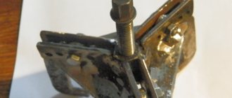
To fix the rotor, I sometimes use a homemade puller similar to the factory one. I made it from old unnecessary pieces of hardware, and it works no worse than the factory one.
If you don't mind the money, you can buy yourself a factory one. It is inexpensive and easier to operate than a steamed turnip: insert the pins into special holes in the rotor, rest the lever on something and calmly unscrew the nut. By the way, such clamps are sold not only in spare parts stores, but also in power tool stores.
In power tool stores, traders position this device as a universal wrench for loosening nuts on angle grinders (angle grinders). It’s called: “universal wrench for angle grinders.” It costs only 160 rubles, and the original, supposedly “correct” one costs 350 rubles.
If you buy the same one for yourself, immediately cut its pins, otherwise they are very long in stock and can damage the generator windings during operation.
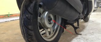
Unscrew the bolts and remove the impeller from the rotor.
Let me digress a little: do not lose the bolts that secure the impeller to the rotor, but it is best to immediately remove them. I had the opportunity to repair a scooter, the owner of which lost the original bolt and tightened another one in its place, but it turned out to be a little longer and broke the windings when starting the engine.
The bolt was only a few millimeters longer than the original one.
We fix the rotor and unscrew the nut. As I already said: in my work I sometimes use homemade tools, in this case a puller.
We unscrew the nut and remove it together with the washer from the rotor. If the puck is not there, then someone has already managed to dig around there before you...
Modification of the standard light on a scooter
Modification of the standard light on a scooter (using the example of Daelim S-five)
In my case, the scooter had an original 35/35 Watt lamp with a ba20d base.
Replacement - Philips BlueVision Ultra Blue 4000 Kelvin with a standard H4 automotive socket.
Sold in blister packs of 1 pc. Very convenient because There is no need to buy a set of two for a scooter. The cost of one such lamp is about 40 UAH.
We remove the hologen skirt (cut/grind off/bite off).
In my case, it prevents me from installing the lamp in the holder in the desired position.
But this must be done very carefully so as not to damage the flask. And by the way, it’s also not advisable to touch it with your hands.
We disconnect the lamp holder from the reflector and expand it with a file/file to the required size.
We adjust everything so that the filaments of the new lamp are in the same place as the old lamp. It is very important. Otherwise, focus is lost.
We fix the lamp in the holder and fix it.
We connect the terminal blocks to the lamp contacts.
We put the holder with the lamp in place in the reflector.
You may have to further adjust the lamp, move it to get into focus and achieve an even light spot. (for example, I removed the plastic and the headlight 10 times)
But the result is amazing. The original 35-watt light bulb was nowhere near it. The reflector does not melt. Moreover, the large LED, which is located in close proximity to the lamp, feels good. The light is bright white (almost throughout the entire rev range. At idle it turns slightly yellow, but after 3000 rpm it becomes completely white), the illumination is simply excellent. With such a kit on a 50 cc scooter, only xenon can compete.
For city driving, low beam is more than enough. The distant one is very powerful, so I only use it on empty, unlit streets and for blinking.
The difference between low and high beam is slightly larger with Philips, unlike a motorcycle bulb. This refers to the difference in lighting range. The distance between the near and far filaments in the bluevision is greater than in the original light bulb.
I would also like to note that in order to fully experience the beauty of a higher-power halogen lamp, you must install a manual starter enricher. (in my case, plus all the optics have been converted to LEDs)
I once traveled with an electric starting enricher - it’s not at all the same:
- brightness is noticeably worse
— the light is yellow, turns white only at the highest speeds
— when the brake light is on, it turns yellow even more
My results in the photo:
I note that the above can only be done on scooters, where the power supply for the dimensions, head light, tidy, etc. Although it comes with variables, it is STABILIZED 12 volts. otherwise, you need to make a stabilizer-rectifier.
Modification of cylinder head 139FMB
Installing xenon on a scooter - without altering the generator
A regular reader of our site under the name Evgeniy, today he will share with us his experience of installing xenon on his scooter. There is no great difficulty in installing this device, the price is affordable, and the difference with a conventional incandescent lamp is very noticeable. So, we sit down comfortably in a chair and read...
In one of the comments, I promised to talk about installing xenon on a scooter, without any modifications to the generator.
This is what xenon is (picture taken from the manufacturer’s website)
- Ignition control unit.
- Lamp
- Connecting wire.
- Adapters for lamps.
Well, now the actual installation process. I would like to note that I did not modify the generator.
First, remove the protective cap from the lamp.
Homemade puller
Unfortunately, homemade, just like factory-made, is not without its drawbacks.
It is moderately reliable, versatile, and cheap, but it is not so convenient to use, and if you do not know how to use it, you can easily break the threads under the bolts of the cooling impeller. Which puller you will use is up to you to decide. I have described all the pros and cons of both options for you.
For myself, I chose the option with a homemade puller. And the price has nothing to do with it. It's all about experience. Over the years of work, I tried a lot of things and eventually came to the conclusion that there is nothing better than a homemade tool puller.
I screwed a bolt from a regular car puller into the nut, attached the washer to the cooling impeller, marked points with a pencil through the holes for the bolts, marked and drilled the holes.
If you don’t want to make a puller, buy a factory one at the store or ask your friends. Just before purchasing, just in case, remove the cooling impeller and look at the condition of the thread.
Electrics and electrical equipment of a scooter
Dedicated to all owners of Chinese scooters...
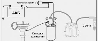
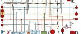
To begin with, I would like to present a wiring diagram for a Chinese scooter.
Since all Chinese scooters are very similar, like Siamese twins, their electrical circuits are practically no different.
The diagram was found on the Internet and is, in my opinion, one of the most successful, since it shows the color of the connecting conductors. This greatly simplifies the diagram and makes it more comfortable to read.
(Click on the image to enlarge. The image will open in a new window).
It is worth noting that in the electrical circuit of a scooter, just like in any electronic circuit, there is a common wire . On a scooter, the common wire is the minus ( - ). In the diagram, the common wire is shown in green . If you look more closely, you will notice that it is connected to all the electrical equipment of the scooter: headlight ( 16 ), turn relay ( 24 ), instrument panel backlight lamp ( 15 ), indicator lamps ( 20 , 36 , 22 , 17 ), tachometer ( 18 ), fuel level sensor ( 14 ), horn ( 31 ), tail light/brake light ( 13 ), start relay ( 10 ) and other devices.
First, let's go over the main elements of the Chinese scooter circuit.
Egnition lock.
Ignition switch ( 12 ) or “Main switch”. The ignition switch is nothing more than a regular multi-position switch. Even though the ignition switch has 3 positions, the electrical circuit uses only 2.
When the key is in the first position, the red and black wires are connected. In this case, the voltage from the battery enters the electric circuit of the scooter, the scooter is ready to start. The fuel level indicator, tachometer, sound signal, turn relay, and ignition circuit are also ready for operation. They are supplied with power from the battery.
If the ignition switch malfunctions, it can be safely replaced with some kind of switch like a toggle switch. The toggle switch must be powerful enough, because the entire electrical circuit of the scooter is, in fact, switched through the ignition switch. Of course, you can do without a toggle switch if you limit yourself to short-circuiting the red and black wires, as the heroes of Hollywood action films once did
.
1 is shorted to the housing (common wire). In this case, engine operation is blocked . Some scooter models have an engine stop button ( 27 ) to block the engine, which, like the ignition switch, connects the white- black and green (common, body) wires.
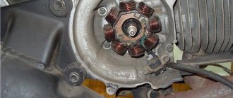
The generator ( 4 ) produces alternating electric current to power all current consumers and charge the battery ( 6 ).
There are 5 wires coming from the generator. One of them is connected to a common wire (frame). The alternating voltage is removed from the white wire and supplied to the relay regulator for subsequent straightening and stabilization. The yellow wire removes voltage, which is used to power the low/high beam lamp, which is installed in the front fairing of the scooter.
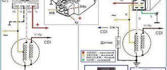
Also in the design of the generator there is a so-called hall sensor . It is not electrically connected to the generator and there are 2 wires coming from it: white- green and red - black . The hall sensor is connected to the CDI ignition module ( 1 ).
Relay regulator.
Regulator relay ( 5 ). People may call it a “stabilizer”, “transistor”, “regulator”, “voltage regulator” or simply “relay”. All these definitions refer to one piece of hardware. This is what the relay regulator looks like.
The relay regulator on Chinese scooters is installed in the front part under a plastic fairing. The relay-regulator itself is attached to the metal base of the scooter in order to reduce the heating of the relay radiator during operation. This is what the relay regulator looks like on a scooter.
In the operation of a scooter, the relay regulator plays a very important role. The task of the relay regulator is to convert the alternating voltage from the generator into direct voltage and limit it to 13.5 - 14.8 volts. This is the voltage required to charge the battery.
The diagram and photo show that there are 4 wires coming from the relay-regulator. Green is the common wire. We have already talked about it. Red is the output of positive DC voltage 13.5 -14.8 volts.
The regulator receives alternating voltage from the generator through the white wire to the relay. Also connected to the regulator is yellow wire coming from the generator. It supplies the regulator with alternating voltage from the generator. Due to the electronic circuit of the regulator, the voltage on this wire is converted into a pulsating one, and is supplied to powerful current consumers - the low and high beam lamps, as well as the dashboard backlight lamps (there may be several of them).
The supply voltage of the lamps is not stabilized, but is limited by the relay regulator at a certain level (about 12V), since at high speeds the alternating voltage supplied from the generator exceeds the permissible limit. I think those who have had their dimensions burned out due to malfunctions of the relay-regulator know this.
Ignition circuit elements.
One of the most important electrical circuits in a scooter is the ignition circuit. It includes the CDI ignition module ( 1 ), ignition coil ( 2 ), spark plug ( 3 ).
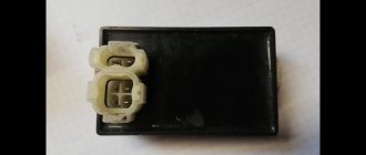
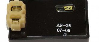
CDI ignition module.
The CDI ignition module ( 1 ) is made in the form of a small box filled with compound. This makes it difficult to disassemble the CDI unit if it malfunctions. Although the modular design of this unit simplifies the process of replacing it.
There are 5 wires connected to the CDI module. The CDI module itself is located in the bottom of the scooter body near the battery compartment and is secured to the frame with a rubber clamp. Access to the CDI block is made difficult by the fact that it is located in the bottom part and is covered with decorative plastic, which has to be completely removed.
Ignition coil.
Ignition coil ( 2 ). The ignition coil itself is located on the right side of the scooter and is mounted on the frame. It is a kind of plastic barrel with two connectors for connection and a high-voltage wire output that goes to the spark plug.
Structurally, the ignition coil is located next to the start relay. To protect against dust, dirt and accidental short circuits, the coil is covered with a rubber cover.
Spark plug.
A7TC spark plug ( 3 ).
The spark plug turned out to be cleverly hidden on the scooter, and it can take quite a long time to find it the first time. But if we “walk” along the high-voltage wire from the ignition coil, the wire will lead us straight to the spark plug cap.
The cap is removed from the candle with a little effort. It is fixed to the spark plug contact with an elastic metal latch.
It is worth noting that the high-voltage wire is connected to the cap without soldering. The insulated stranded wire is simply screwed onto the screw contact built into the cap. Therefore, you should not pull the wire too hard, otherwise you can pull the wire out of the cap. This can be easily fixed, but the wire will have to be shortened by 0.5 - 1 cm.
It's not so easy to get to the spark plug itself. To dismantle it, a socket wrench is required. With its help, the candle is simply unscrewed from its seat.
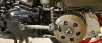
Starter ( 8 ). The starter is used to start the engine. It is located in the middle part of the scooter next to the engine. It's not easy to get to.
The starting of the starter is controlled by the starting relay (10).
The start relay is located on the right side of the scooter frame. The starting relay receives a thick red wire from the positive terminal of the battery. This is how the start relay is energized.
Fuel gauge and indicator.
The fuel level sensor ( 14 ) is built into the fuel tank.
There are three wires coming from the sensor. Green is common (minus power), and the other two sensors are connected to the fuel level indicator ( 11 ), which is installed on the dashboard of the scooter.
The fuel sensor ( 14 ) and indicator ( 11 ) are one device and are powered by a constant stabilized voltage. Since these two devices are spaced apart, they are connected by a three-pin connector. The positive supply voltage is supplied to the fuel indicator and sensor via the black wire from the ignition switch.
If you open the three-pin connector coming from the fuel sensor, the fuel indicator will no longer show the fuel level in the tank. Therefore, if your fuel indicator does not work, then check the connecting connector between the sensor and the fuel indicator, and also make sure that they are receiving power.
It is also worth remembering that the supply voltage is supplied to the sensor and indicator when the ignition switch is in the closed position ( 12 ). According to the diagram, this is the right position.
Turns relay.
Turn relay or breaker relay ( 24 ). Serves to control the front and rear turn signal lamps.
As a rule, the turn relay is installed next to the instruments (speedometer, tachometer, fuel level indicator) on the dashboard. In order to see it you need to remove the decorative plastic. It looks like a small plastic barrel with three terminals. When the turn signals are on, it makes characteristic clicks with a frequency of about 1 Hz.
After the turn relay, a turn signal switch ( 23 ) is installed. This is an ordinary key switch that switches the positive voltage from the turn relays (gray wire) to the lamps. If you look at the diagram, when the switch is in the right position ( 23 ), we supply voltage through the blue wire to the right front ( 21 ) and right rear ( 32 ) indicator lamp. If the switch is in the left position, then the gray wire is shorted to the orange one, and we supply power to the left front ( 19 ) and left rear ( 33 ) indicator lamp. In addition, in parallel with the corresponding indicator lamps ( 19 , 20 , 32 , 33 ), signal lamps ( 20 and 22 ) are connected, which are located on the dashboard of the scooter and serve as a purely informational signal for the scooter driver.
Sound signal.
The sound signal ( 31 ) of the scooter is located under the plastic fairing of the scooter next to the relay regulator.
The audio signal supply voltage is constant. It comes from a relay regulator or battery (if the engine is turned off) through the ignition switch and the horn button ( 25).
Low/high beam lamp ( 16 ). Yes, the same one that lights our way in the dark.
The lamp itself is double with two filaments and three contacts for connection to an electrical circuit. One of the contacts, of course, is common. Lamp power 25W, supply voltage 12V. It burns shamelessly when the relay-regulator is faulty due to the fact that it does not limit the voltage amplitude at 12 volts, which leads to the fact that a voltage of 16 - 27 volts, or even more, is supplied to the lamp. It all depends on the speed.
Therefore, if at idle the lamp shines very brightly, and not at full intensity, then it is better to turn it off and check the relay regulator. If you leave everything as is, the low/high beam lamp will burn out, which is sad. Its cost is decent.
In the photo next to it is the turn signal lamp (red). Lamp power 5W for supply voltage 12V.
Removing the rotor
Insert the bolts into the required holes. We take the bolts from the cooling impeller - they fit there perfectly. In order not to touch the windings, we screw restrictive nuts onto the bolts - they will not allow the bolts to go deep inside the generator.
We apply the puller to the rotor and screw the bolts into the holes. In order not to break the thread, slightly tighten the central bolt and see if all the bolts are tight. If any bolt is loose, tighten it.
This way we will evenly distribute the load between the bolts. If you neglect this moment, the entire load, unnoticed by you, can rest on only one bolt or two, and then they will break out of the rotor along with the thread. We don't need this, of course.
Now the main thing: what is there, you cannot tighten the central bolt by force. In this case, excessive force will not achieve anything. Everything must be done slowly and competently. Otherwise, you will tear the puller out of the rotor along with the roots, and then your budget will become completely financially insolvent.
You only need to remove the rotor this way: Lightly tighten the central bolt of the puller with a wrench, lightly hit the end of the central bolt with a small hammer - the rotor, usually, after the first blow, flies off the cone without talking, if it doesn’t fly off, pull the bolt again and hit again.
I learned this technique back in 1996, when I had the opportunity to remove the reel drive pulley of the Kolos combine harvester from the shaft. If it weren’t for one smart person who promptly told me how to work with a puller correctly, then I would have smashed both the pulley and the puller and the sledgehammer along with the combine...
The rotor sits on a key. If you do not plan to further disassemble the engine, leave it as is. And if you plan, you better get it, otherwise you’ll lose it.
A broken key can be easily removed with small pliers; if the key fits very tightly, leave it, it won’t get away from you.
So that you don’t have to guess later how your stator was positioned, we put marks with a core or take a photo, remember it, or do something else. This is necessary in order to protect yourself from problems with a lost outline.
It happens that when installing it back, the stator is installed in reverse, and then depending on your luck: everything may go without consequences, or the spark may disappear or interruptions may appear. To avoid this, any, not just CDI-type scooter generators must be installed exactly as they were originally installed. If you follow this golden rule, you will be happy.
We remove the stator. Installation of the generator is carried out in reverse order.
How to make a light from a generator on a scooter
On my scooter I get 2 headlights, one low beam and the other high beam. I want to make two of them burn at once, and buy a halogen lamp that will have low and high beam in one lamp.
how to do it? And I also want the lights to come from the Akum, and not from the generator.
please help, if possible drawings.
FleischStorm
, here you need to find out what light to switch both headlights to low or high? It will not work from the battery, since the battery is recharged from the generator, and even if you connect it to the battery, the light bulbs will not last long due to the voltage drop. Here you need to resolder the wires in the face and bring them to a certain light (low or high).
That’s why I ask what exactly a person wants to get from his alteration.
Can your generator handle two at once?! I think no.
It’s possible, I checked it myself, I burned 3 fuses until I connected everything correctly.
If you connect two headlights to a battery without disconnecting the relay-controller (in common parlance, although this is not a relay at all), then this relay will burn out in this case! You can check. If you connect it to a battery without a relay, the battery will run out very quickly. (Discharge rate depends on capacity). If you connect both headlights to a generator, they will glow dimly. Conclusion: for normal operation of the headlights, you need to convert the electrics to xenon. That's exactly what I did. I think that not everyone can handle this. But if you want, you can.
NGK
, you don’t even need to prove anything here. It's obvious. You can't improve a technique without some modification. The main thing is to understand what affects what and how to do it and not break it. There is a good article from Juraj from Moscow. That's exactly what I did according to her. Everything is chewed and shown. They don’t do it right at the factory right away because the cost of the moped will be higher and more difficult to sell.
firstly, thanks to you, I have someone to discuss the topic with