"Wet" double
There are two types of clutch, dry and wet (also multi-plate in oil). The so-called “wet” has better cooling. Most often it is installed on gearboxes with a torque of 250 Nm and above. An example would be the Bugatti Veyron, whose torque reaches 1250 Nm.
The second set of discs is mounted on separate hubs, which are located on the input shaft of the corresponding row of gears. In the normal position the mechanism will be open. As for the closure, this is done thanks to hydraulic cylinders controlled by an electrohydraulic module. The disks take their initial position due to springs.
Depending on the design of the double clutch, the friction disc packs can be arranged differently, concentrically or parallel. Concentrically, when the couplings are located in the same plane and perpendicular to the input shaft. In this position the couplings are more compact. Typically used in gearboxes with front-wheel drive and a transverse engine.
As a rule, the internal clutch is responsible for shifting even-numbered gears, and the external clutch is responsible for shifting odd-numbered gears. It becomes clear that such a set is designed to transmit high torque.
Parallel - when the couplings are located one behind the other. As a rule, this arrangement is used for rear-wheel drive cars.
REPAIR OF THE KICKSTARTER OF THE MOTORCYCLE “IZH-JUPITER”
After several years of operation of the IZH-Jupiter-ZK-01 motorcycle, released in 1980, the kickstarter pedal began to “fail,” making it impossible to start the engine.
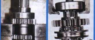
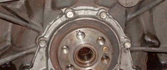
At first this appeared sporadically, then more and more often, and finally the mechanism completely failed. After disassembling and superficial inspection of the ratchet clutch (Fig. 1), I found slight wear and small nicks in the teeth of ratchet 2 (part designation according to the catalog IZHYU1-128) and gears 4 (part IZHYU1-127). It seemed that by themselves they should not lead to refusal. An attempt was made to eliminate the defect by installing a homemade, stiffer spring 3 instead of the factory part IZHYU1-143. This caused the engagement to occur more frequently, but the defect could not be completely eliminated. I had to disassemble the unit again and study its operation more carefully. At the same time, it was discovered that, firstly, due to uneven wear, and perhaps inaccuracy in the manufacture of parts in some positions, simultaneous engagement of all teeth of the ratchet clutch is not ensured. In addition, the kickstarter gear 4 has a small height H; Even with slight wear and an increase in the gap, it warps - this is shown in Fig. 1. The picture that emerges is something like this. First, when you press the start pedal, when sector 6 of the kickstarter acts on gear 4, engagement occurs only with individual teeth. Then, as the parts wear out, the skew of the kickstarter gears 4 increases. Some teeth begin to work with the upper worn, rounded part. Pushing. the component increases, the ratchet teeth disengage (Figure 2) and the kickstarter pedal “falls”. Of course, in this situation it would be necessary to replace the worn parts - but where will you get them?
And I had to think about restoring the operation of the node on my own. There was no point in restoring the leading edge of the teeth by welding or in any other way at home (in mine, at least). The teeth are well hardened and their manual machining is almost impossible. A fairly common situation has arisen when it seems that nothing can be done, but it is absolutely necessary.
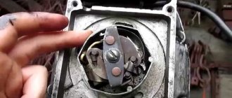
I have a small selection of tools; The most versatile device is an electric sharpener. I pinned all my hopes on him. For ease of operation, rivets 5 securing the ratchet were drilled out and the ratchet was removed from the outer clutch drum. Using a hard steel plate, the whetstone was “sharpened” to produce a sharp working edge. The first attempt to process the teeth, naturally, on another, completely unusable similar part, was unsuccessful, since the height of the teeth was small, and the working surface of the stone quickly wore out and became rounded. Then, instead of a stone, I attached a cutting sanding wheel approximately 2.5 mm thick to the sharpening axis.
Since it is impossible to apply lateral forces to the cutting wheel, I did not even try to restore the previous shape of the teeth. I immediately decided to trim them so as to ensure reliable engagement even when exposed to a twisting force. It was uncomfortable to work with, I held the parts suspended in my hands, and assessed the result “by eye.” True, all the work was carried out slowly, in order to avoid, at least, gross mistakes and not to overheat the metal of the teeth. In Fig. Figure 4 shows the electric motor of the sharpener 1, the cutting wheel 2 and the position of the workpiece 3.
In general, the processing turned out to be rough, but after assembling the unit and installing it in place, the final result, as they say, exceeded all expectations - the performance was completely restored, the engagement became absolutely reliable (Fig. 3). For those who want to repair the trigger mechanism on their motorcycle, go-kart or walk-behind tractor in this way, I can advise you to point the cutting wheel at an angle of approximately 45° (Fig. 4), but this value depends on the thickness of the circle itself. It is necessary to strive to ensure that the angle of engagement of the teeth is within 20-30°, and the engagement is carried out by all teeth simultaneously.
Do not strive to achieve a necessarily sharp upper edge of the teeth - in this case you will inevitably overheat it and weaken its strength. It is better not to approach the top of the tooth closer than 1-1.5 mm at all (see Fig. 16). Perhaps specialists with access to good equipment will say that the repairs were carried out in a barbaric manner. I won't argue. But, on the one hand, if necessary, many motorcycle owners can easily repeat it on their own, and on the other hand, without it, my motorcycle would have been sitting motionless in the garage for two years.
Clutch faults
Possible malfunctions that may appear during operation of IZ motorcycles.
The clutch of IZH Jupiter IZH Planet is slipping reasons
The malfunction is noticeable during sudden acceleration. We increase the speed, but the motorcycle does not accelerate. The same thing happens when driving on a steep hill as the load increases. The motorcycle cannot overcome the obstacle and stops, although the crankshaft speed does not drop. The discs get very hot and wear out quickly. It is impossible to operate the equipment in this condition; the cause must be found and eliminated.
This malfunction indicates that the disks are poorly pressed against each other.
There may be several reasons:
- The adjustment was not carried out correctly
- The springs have lost their former elasticity
- The discs have worn out and become thinner.
- Wear of drive parts
A serious problem could be a jammed control cable. The reason is damage to the shell and the resulting rust underneath. Gentle cleaning and lubrication, better replacement.
Check and wash the adjustment mechanism itself located in the right engine cover. Small particles of road sand that get into the mechanism with water can slow down the operation. After squeezing the lever, the parts do not return to their original position.
Drives clutch IZ Planet IZ Jupiter reasons
The clutch is driving - this is when the lever is squeezed all the way, and when the speed is turned on, the motorcycle immediately starts moving and cannot be stopped. You press the brake, the engine stalls. This indicates that the clutch is not completely disengaged.
The main reason is the springs that compress the discs. The discs are not evenly weakened and in some places are in strong contact with each other. The springs need to be adjusted correctly.
There is too much free play in the control lever on the steering wheel. If adjustment is not possible, replace worn control parts.
You need to check the pusher, which is located inside the input shaft of the gearbox. Perhaps the rod has become shorter.
Be sure to check the presence of the ball. Often during disassembly it rolls out and gets lost.
The ball is located inside the input shaft of a two-cylinder engine between the pusher and the thrust rod.
For a single-cylinder unit, the ball is located in the right cover between the screw with a control nut and the thrust rod in the input shaft of the box.
- IZH Planet 5 characteristics review power weight video
- Rectifier-voltage regulator
- Ignition installation
- Generator IZH 281.3071
- IZH Planet 4 ignition switch
- Malfunctions of the IZh motorcycle
- Air filter for IZH Planet 4 motorcycle
- Motorcycle IZH 56 technical specifications
- Motorcycle IZH Jupiter disassembly and assembly of gearbox
Adjusting the electronic ignition system on Izh Planet 5. How to set the ignition on the Planet?
If you are the owner of an IL, the ignition of Planet 5 electronic type can be adjusted in the following way:
- set the advance angle (3.5 mm to the top dead center mark, in this case the sensor will show a pulse only when the modulator leaves the gap);
- start the engine.
As a rule, this option for setting up the ignition on Izh Planet 5 works without problems. Moreover, as a reserve for installing the ignition on Izh Planet 5, you can use a contact system for starting the power unit.
So, we figured out how to set the ignition on the Planet. With proper adjustment of the engine starting system, your motorcycle will start normally, and you will be able to experience all the delights of driving such a two-wheeled vehicle.
Adjusting the IZH Jupiter clutch
On IZH-Yu and IZH-YUK motorcycles, adjusting the clutch release mechanism begins with adjusting the machine, for which the adjusting screw is screwed in all the way and released 1/4.1/2 turn, then tighten the lock nut. Correct adjustment is checked by pressing the switch pedal in any direction. Moving the front end of the shift pedal 5-5.5 mm from the neutral position should not lead to movement of the pressure plate. Then adjust by manually pressing the adjustment screw located in the left column of the clutch lever
on the steering wheel (free play 5-10 mm)
CLUTCH OF MOTORCYCLE “MINSK” MMVZ 3.111
The clutch is designed to disconnect the engine and transmission when changing gears, during a short stop with the gear engaged, and when braking.
The adjustment is made as follows:
1. Unscrew the screws of the right cover plug 39 (Fig. 3). 2. Loosen the adjusting screw locknut. 3. By screwing in or out the adjusting screw, set the free play at the end of the clutch lever on the steering wheel to 5-10 mm. It must be remembered that when screwing in the screw, the free play decreases, and when turning it out, it increases.
If the clutch “leads,” that is, when the lever is fully depressed, the motorcycle tends to move, then the adjusting screw must be screwed in. If the clutch “slips,” that is, when the lever is completely released, the motorcycle stands still, or the engine speed does not correspond to the speed of the motorcycle in a given gear, which is especially noticeable when driving on an incline, then the adjusting screw must be unscrewed.
After adjusting the clutch, the adjusting screw should be locked.
Rice. 12. Clutch: 1 — driven discs; 2 - drive disk; 3 — pressure disk; 4 - pressure spring; 5 — rod fungus; 6 — driven drum nut; 7 — lock washer; 8 — driven drum; 9 — driving drum; 10 — intermediate washer; 11 — driven gear of the motor transmission; 12 - ratchet; 13 — ratchet gear of the trigger mechanism; 14 - spring of the ratchet gear; - 15 - bushing of the driven gear; 16 — bearing retaining ring; 17 — input shaft bearing; 18 — input shaft; 19 — clutch release rod; 20 - worm spring; 21 — worm lever; 22 — right crankcase cover; 23 - ball; 24 - worm; 25 — worm thrust washer; 26 - lock nut; 27 — adjusting screw; 28 — secondary shaft nut; 29 — oil seal; 30 - lock washer.
Disassembling and assembling the clutch.
1. Using a wire hook (or knitting needle), disconnect the springs from the pressure plate and remove the disc. 2. Remove the clutch fungus and remove the discs. 3. Use a screwdriver to bend the lock washer. 4. Secure the clutch drum with a special device (Fig. 13), or, in the absence of one, with a screwdriver (which is highly undesirable), and unscrew the driven drum nut. It should be remembered that the thread is left-handed!
Rice. 13. Device for disassembling the clutch.
5. Without removing the special device from the clutch, unscrew the nut securing the gear on the crankshaft journal. 6. Remove the clutch together with the motor chain and gear. 7. Remove the driven gear bushing and thrust washer. 8. Remove the key from the crankshaft journal. Reassemble in reverse order.
Clutch care involves lubricating the cable, lever and worm, as well as timely and correct adjustment of the free play of the lever.
The most common clutch malfunctions are:
1. The clutch is not adjustable - the pressure springs may weaken, the cable may stretch out, or the pressure plate may bend. 2. The clutch does not disengage - possible jamming of the worm due to poor lubrication or sand ingress, jamming of the rod due to its bending, welding of the rod to the input shaft due to insufficient lubrication of the gearbox, misalignment of the discs, jamming of the discs on the splines or in the grooves of the drum, self-unscrewing of the driven drum nut.
content .. 11 12 17 ..
Switch P-200
Light switch with horn button (located on the left side of the steering wheel). To switch the low and high beam circuit, a P-200 type switch is used with a built-in push-button horn switch for three operating positions: neutral - the headlight lamp is off; far right – low beam is on; far left – high beam is on.
The horn button has a movable contact connected to ground and a fixed contact connected to one of the wires coming from the horn terminal. When you press the button, the contacts close and the signal circuit is completed.
Functional purpose of the gearshift clutch
Before you adjust the clutch on the Izh-Jupiter 5 motorcycle, it’s a good idea to understand its purpose and principle of operation. The essence of the transmission clutch:
- Ensuring the transmission of torque from the large gear of the motor transmission to the gearbox input shaft.
- Short-term separation and smooth connection of transmission elements to each other.
Izh motorcycles were equipped with a mechanical clutch, the operation of which is based on the friction force between the driven and driving disks. It is a multi-disc design operating in an oil bath - a classic arrangement that the Izhevsk Machine Plant used until 2008. Working in tandem, the main chain drive and four-speed gearbox are reliable and proven by many generations of motorcyclists.
"Sores"
“Planet” was good in its time, except for the ill-conceived launch mechanism. For those who have “Planet”, I think there is no need to explain what “return” means. Personally, once it gave so much that it tore the kickstarter shaft in half, bent the gearshift shaft and tore the ratchet on the clutch basket. Those whose slippers fly into the sky are lucky compared to my version...
What does a clutch consist of?
In order not to break the clutch, you need to know not only how it works superficially and what its functions are, but also what parts it consists of. The main components include the driven and driven parts, the shutdown mechanism and the pressure system.
The engine rotational torque is transmitted from the flywheel to the drive parts, which in turn transmit torque to the gearbox drive shaft. The frictional moment is provided thanks to a pressure mechanism, which, thanks to the tight coupling of the driven and driven parts, gives the long-awaited result of movement.
Disengaging the clutch is considered important. So one disk, on which springs are located peripherally, is located in a cast-iron crankcase, which in turn is located in the engine block crankcase.
The drive part includes the clutch housing and flywheel, the latter in turn is attached to the crankshaft flywheel using six special bolts. The pressure plate is located in the middle part of the casing. The torque of the pressure plate is transmitted from the flywheel through three protrusions that are located in the disk and enter the casing windows. The driven disk, hub, and drive shaft of the gearbox are the main and mandatory components of the driven part of the clutch.
On both sides of the driven disk there are friction linings made of a copper-asbestos composition (or another metal-asbestos composition), which can withstand unusually high temperatures and are known for their friction properties. The driven disk is connected to the hub with rivets or through springs. These springs are an integral part of the spring-friction damper of rotating vibrations (that is, the damper)
CLUTCH MECHANISM
Clutch mechanism
is a device in which torque is transmitted due to the work of friction forces. The clutch mechanism allows you to briefly separate the engine and gearbox, and then smoothly connect them. The elements of the mechanism are enclosed in a clutch housing, which is attached to the engine crankcase.
The clutch mechanism consists of
:
- crankcase and casing,
- drive disk (which is the engine flywheel),
- pressure plate with springs,
- driven disk with wear-resistant linings.
The driven disk is constantly pressed against the flywheel by the pressure disk under the influence of strong springs. Due to the enormous frictional forces between the flywheel, driven and pressure plates, they all rotate together when the engine is running. But only when the driver does not touch the clutch pedal, regardless of whether the car is moving or standing still.
To start the machine moving, it is necessary to press the driven disk connected to the drive wheels to the rotating flywheel, that is, engage the clutch.
And this is a difficult task, since the angular speed of rotation of the flywheel is 20 - 25 revolutions per second, and the speed of rotation of the drive wheels is zero. Clutch engaged
In the first stage
work to engage the clutch - slightly release the pedal, i.e. We allow the springs of the pressure plate to bring the driven disk to the flywheel until they lightly touch. Due to frictional forces, the disk, slipping for some time relative to the flywheel, will also begin to rotate, and the car will slowly crawl.
At the second stage
– we hold the driven disk from any movement, i.e. hold the clutch pedal in the middle position for two to three seconds so that the speed of rotation of the flywheel and disc is equal. At the same time, the machine increases its speed.
At the third stage
— the flywheel, together with the pressure and driven disks, already rotates together without slipping and at the same speed, transmitting 100% torque to the gearbox and then to the drive wheels of the car. This corresponds to the state of the clutch mechanism - engaged, the car is moving. Now all that remains is to completely release the clutch pedal and remove your foot from it.
If you release the clutch pedal sharply when starting to move, the car will “jump” forward and the engine will stall.
To release the clutch
The driver presses the pedal, and the pressure plate moves away from the flywheel and releases the driven disk, interrupting the transmission of torque from the engine to the gearbox.
Press the clutch pedal fairly quickly, but not abruptly, with a calm movement until the end of the pedal stroke. The clutch is disengaged
after mastering the operation of the clutch pedal in three stages
Generator
The motorcycle is equipped with a 3-phase alternator, which has an electromagnetic excitation circuit. The principle of its operation is based on some features. So, the electrical circuit of “IZH Planet-4” looks like this: the current is supplied to the rectifier, which, in turn, converts it into direct current, then supplies it to consumers. The factory instructions for the generator contain the following elements:
Voltage regulator with rectifier “BPV-14-10”;
The head light circuit consists of the rear brake light, parking light and color control light. The motorcycle is equipped with a speedometer with mileage indicators (daily and total), a tachometer, indicator lamps for turn signals and head lights, a voltmeter and an engine temperature sensor. Very often during operation it is necessary to adjust the gap between the contacts of the breaker. To do this, it is best to use a diagram and special tools to know which elements need to be dismantled.
While easily fixing mechanical failures, motorcyclists experience difficulties if the electrics fail. It’s completely in vain, the wiring diagram of the planet Izh 5 is not complicated, it’s easy to figure out.
There is no need to have special stands and equipment for repairs. A minimum knowledge of electrical engineering and a simple avometer (tester) is enough; even often you can get by with just a test lamp.
We will tell you in more detail about the main electrical wiring components and possible malfunctions. The Izh Planet wiring diagram makes it easy to find a broken wire or damaged insulation (for example, a bad contact always gets hot).
In this case, we look to see if there is a spark at the coil output and at the output at the spark plug contact. Let's take a closer look at the main wiring components of the Izh Planet.
Clutch Spring Adjustment
Adjusting the springs is not difficult, that's the main thing. understand correctly. Let's start by mounting the motorcycle on the center step. Then remove the cap before draining the oil. The clutch lever is compressed to the limit and will definitely lock. Next comes speed, preferably first. Take the wheel and start spinning. We are trying to determine how much effort we are making. We look at the clutch as it rotates and determine which springs are loose. We mark them with chalk and then tighten them. We start turning the wheel again, and if you feel that the wheel is turning easier, that means everything is done correctly. The process must be repeated to achieve the best result. After that, we check the result while moving. If the load starts to clip when the load increases. All springs must be tightened using nuts. In this case, all nuts must have the same number of turns.
Setting up the remote control for the JUPITER-T5-PM TV set-top box
Instructions for setting up remote controls for Jupiter series consoles.
A set-top box with a huge hard drive on board by the standards of TV set-top boxes - 1000 Gigabytes (although in some regions for some reason it’s 500, which, in general, is also not bad. Motorola and Kisko have 100 Gigabytes each, Tatungs have – 300 each. The numbers are taken from personal installation experience). It comes with a native remote control, a universal one will not work with it.
This miracle from Beeline appeared relatively recently (since January 2017, to be exact). There is still very little information on this remote control, below is everything that has been tested and what I use successfully myself (I will be extremely grateful to everyone who is not too lazy to send the original instructions for this remote control, because for some reason the box contains instructions from Tatung). The set-top box is re-flashed with Beeline firmware, the factory one is completely different. So far, user reviews are completely contradictory. Some people like it unconditionally, others absolutely do not. My personal opinion is that the prefix is still “damp”. The idea is not bad, the implementation, as always, is not very good. But, knowing the manic persistence of the Beeline people to push through even obviously failed products, one can only hope that over time they will bring Jupiter to mind, and there will be quite a good console. In the meantime, I strongly recommend that you manually update the firmware to the latest, otherwise failures and troubles when viewing are GUARANTEED (automatic firmware updates are carried out about once every one to three months, there is no exact data, apparently it depends on the load)
The USB connector on the front panel of the set-top box is intended for testing the set-top box by service workers and for nothing more. Those. You won't be able to insert a flash drive with a movie and watch it. The only thing this “hole” can be useful for is that you can use it as a charger for your mobile phone – the signal is powerful enough to quickly charge any gadget.
- Setting up the remote control for the Beeline Jupiter-T5-PM set-top box: (rebinding in case of failures)
- Linking the Jupiter-T5-PM remote control to a TV: (TV)
- Full reset of the Jupiter-T5-PM remote control
- Instructions for setting up the Jupiter-T5-PM remote control in PDF from Beeline:
Setting up the remote control for the Beeline Jupiter-T5-PM set-top box: (rebinding in case of failures)
In general, the remote control to this set-top box should already be linked by default. The sequence below will help you “rebind” the remote control to the set-top box again.
- Press the STB and wait.
- When the red LED lights up continuously, release STB .
- Enter code 7 7 7 7.
- Press the STB and wait until the red LED goes out.
- Use it.
Clutch adjustment
The clutch is the connecting link between the gearbox and the control lever, so you need to know how to adjust the clutch on a walk-behind tractor. When the clutch fails, its failures are immediately visible:
- in this case, the clutch is fully depressed, and the walk-behind tractor breaks away. To eliminate these problems, tighten the adjustment screw;
- If the clutch is in the released state, but the walk-behind tractor still does not produce the required speed or stands still, then it is necessary to loosen the screw.
If you hear a strange sound from the gearbox during use, promptly stop all work. The most common problem is insufficient oil or poor quality. It is necessary to check the oil level every time before starting work. If the oil is changed, but the noise does not stop, then you need to contact a service center for diagnostics. If problems with gear shifting are detected, the causes must be sought in the correct settings of the clutch, worn gearbox parts or worn shaft splines.
Knowledge of the correct adjustment of the clutch on a walk-behind tractor will ensure your safety and efficiency of the work process. To purchase new products, you can go to!
The Neva MB-2 walk-behind tractor is an agricultural unit designed to work on a wide variety of soil types, including previously uncultivated soil.
Motoblock "Neva" MB 2B-6.5RS
Available in various modifications with different types of engines:
- MB-2B-6.0,
- MB-2B-6.5Pro,
- MB-2B-7.5Pro,
- MB-2K-7.5,
- MB-2N-5.5,
- MB-2S-6.0Pro,
- MB-2S-7.0Pro,
- MB-2S-9.0Pro,
The main work that can be performed on the Neva MB-2 walk-behind tractor is:
- plowing the soil;
- cultivation, milling;
- watering (pumping station);
- hilling;
- cleaning areas from grass, snow, etc.;
- harvesting potatoes, onions, etc.
Caring for a sunrise motorcycle generator - how to remove, what to check and install correctly
Generator maintenance mainly comes down to tightening the threaded fasteners of the generator stator and rotor, as well as the wire terminals.
In order to remove the generator, you must:
- disconnect the wires of the ignition circuit, sensor, brake light and direction indicators from the generator terminals;
- unscrew the three screws securing the stator to the crankcase and remove the stator;
- Unscrew the bolt securing the generator rotor and, with light, careful blows of a wooden hammer on opposite sides of the rotor, remove it from the trunnion and remove the key.
Checking the removed parts
After removing the generator stator and rotor, wash the parts with clean gasoline and carefully inspect them. Disassemble the wire fastening terminals on the stator. Wipe dry all insulating parts of the terminals.
Generator installation
Installation is carried out in the reverse order, in this case it is necessary:
- check the runout of the generator rotor, which should be no more than 0.1 mm with the bolt secured;
- tighten the generator stator without distortions, ensuring a tight fit to all three supports;
- install the ignition correctly;
- The generator wires must be securely fastened and well insulated from each other.
Types of clutch
By type of friction.
The type described above has the so-called “dry” type of friction. That is, all structural elements do not have any lubrication; moreover, it is not allowed at all, since it can affect the adhesion properties of the interacting surfaces of the disks.
But there are types in which the components are in an oil bath - the so-called “wet”.
But this type is practically not used on cars, although it can be found in the design of some motorcycles.
In general, the essence of the operation of this clutch is no different from the “dry” one, with the only difference being that the crankcase in which the components are located is filled with oil.
By number of threads.
As for the number of flows, here friction type clutches are divided into single-flow and double-flow.
In the first case, rotation from the engine is transmitted to only one element. In the type described above, it is the gearbox input shaft.
But special equipment often uses a double-flow clutch.
A distinctive feature from single-flow is the transmission of rotation to two shafts. But for this, another driven disk has been added to the design.
Most often it is found on tractors (the second flow ensures the rotation of the power take-off shaft).
As for passenger vehicles, this type has found application in cars with a robotic gearbox (more about it below).
By the number of driven disks.
Regarding the number of driven discs, in addition to single-disc clutches, there are also double-disc and multi-disc clutches.
The first version of the double-disc clutch is used on the double-flow type. In it, rotation from one driven disk is transmitted to the gearbox shaft, and from the second - to the PTO.
This design made it possible to increase the functionality of the equipment (for example, on tractors, thanks to the power take-off shaft, it is possible to aggregate it with various mechanisms).
But a double-disc clutch can also be single-flow (rotation from two driven discs is transmitted to only one element - the gearbox shaft).
This design has found application in cargo vehicles (in most cases, although this type can also be found on sports cars, as well as some motorcycles), where, due to the high power of the motors, the transmission of high torques is required.
Multi-disc clutches are a package of discs - driving and driven, alternating with each other. This package is placed in a basket consisting of two drums - a leader and a slave.
Otherwise, the essence of this type of design is no different from a conventional clutch - the discs are connected to the corresponding drum springs, pressed against each other, due to which friction occurs between the discs.
When the drive is activated, one of the drums moves away, thereby interrupting the flow. This type of clutch can only be found on motorcycles.
By drive type.
Several types of drives are used to control the unit:
- Mechanical (the transfer of force from the pedal to the bearing fork is done using a system of levers or a cable);
- Hydraulic (force is transmitted through two cylinders - the main and the working, connected to each other by a pipeline filled with liquid);
- Electric (used in systems with automatic clutch control. The clutch elements are acted upon here by means of electric motors with servo drives);
- Combined (the drive combines several of the above types, for example, hydromechanical).
Additionally, special equipment often uses a variety of drive amplifiers.
How to delete a sent photo on WhatsApp
You can now send photos and videos that disappear after they've been opened via View Once on WhatsApp, giving you more control over your chats privacy! pic.twitter.com/Ig5BWbX1Ow
Firstly, the recipient might simply not have time to view the contents of the attachments during the time allotted to him for viewing. And, secondly, it was not so safe, given that such a message could be opened several times, copied or even forwarded before it was deleted.
The automatic deletion mechanism does not apply to all messages, but only to media attachments. That is, you can count on the fact that after the first viewing, only the photo, video or document that you sent to the recipient will be deleted. The innovation does not apply to text messages and voice recordings.
Since this feature only appeared in the latest version of WhatsApp, you will have to upgrade to take advantage of it. Even if you have the auto-update feature active, this does not guarantee that the update will be installed. The new version of the messenger was released 3 days ago, but for some reason the iPhone did not install it, so I had to do it manually.
- Launch WhatsApp and select a chat with the desired interlocutor;
- Click on the “+” icon to the left of the message dialing line;
You definitely can't go wrong by turning on auto-delete
- Select a photo or video to send;
- Click on the number in the circle to enable auto-delete.
Common clutch malfunctions and their symptoms
- Incomplete engagement of the clutch (with “slipping”) is a consequence of oiling or wear of the friction linings of the driven disk, broken springs, and incorrect amplitude of the pedal stroke (its small free play). To eliminate this malfunction, it is necessary to replace the driven disk, eliminate scuffs on the disks, and inspect the drive for malfunctions. When “slippage” occurs, when the clutch pedal is fully released, the disks slip one against the other. Due to prolonged slipping, the discs begin to heat up significantly, the steel driven disc may become warped, and the cast-iron flywheel and pressure plates (or pressure plates) may become cracked. Friction linings wear out and burn at an accelerated rate, and this burnt smell reaches the cabin. If not repaired, the process gradually progresses, first at high, then at low speeds. To the point where it becomes impossible to even move away in first gear.
- Incomplete disengagement of the clutch (when the clutch “drives”) is a consequence of large free play of the clutch, broken springs, a warped driven disk or an incorrectly installed pressure disk. This is also possible when the release levers are deformed; or the release bearing jams and does not move with the pressure clutch. It is possible that the clutch driven disc does not move along the splines (the lubricant has thickened or become dirty). To eliminate this malfunction, it is necessary to remove air from the hydraulic drive, adjust the free travel of the pedal, and replace inoperative disks and springs. Incomplete shutdown is manifested by the crunching sounds of gears when changing gears and, accordingly, leads to accelerated wear of gearbox parts.
- Jerks when engaging the clutch. When the car, despite the smooth release of the clutch pedal, starts jerking, this indicates the destruction of the friction linings, warping of the driven disk, or the breakdown of the damper springs, or wear of the friction washers. It is also possible that the driven disk may jam when moving along the splines of the gearbox input shaft, as well as jamming of the push clutch or destruction of the release bearing.
- Malfunctions of the hydraulic drive system. If air gets into the hydraulic clutch release drive, the pedal may “sink”, and as a result, the clutch may not be completely released. In this case, it is necessary to remove air bubbles with some of the fluid (bleed the clutch) and add fresh fluid. When in cable-driven mechanisms the clutch does not disengage at all, the cable may have broken. When the clutch pedal does not return to its original position, the return spring has become disconnected. If, when the clutch is disengaged, there is a strong noise generated by the release bearing, this indicates its wear.
If the clutch drive is mechanical (lever or cable), then as the friction linings wear out, the clutch pedal will gradually rise, but with a hydraulic drive, the pedal does not change its position, and the fluid level in the reservoir decreases.
So, the clutch mechanism plays a huge role in the functioning of any car or tractor. The technical condition of the entire vehicle largely depends on its serviceability and performance.
Therefore, to ensure long and reliable operation of all elements of the clutch mechanism, it is important to use it smoothly, and without the need to practice excessively long presses on the pedal. Under such gentle operating conditions, the clutch will last a long time
Model features
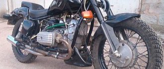
Therefore, even today, enthusiasts retrieve famous motorcycles from dusty sheds and garages, restore them to their original form and, as before, give the spirit of freedom to their owners.
Taking a motorcycle out of the woodshed, there is hope that it will return to service again
What is especially pleasing is the interest of modern youth in domestic technology. This article is intended for them and their parents who had the opportunity to ride Izhaks, Jupiters and Planets .
Electrical diagram
The IZH Jupiter 3 model appeared as an improved example of the previously produced IZH Jupiter 2. For the first time in domestic practice, a motorcycle received turn signals, and therefore the wiring diagram of the IZH Jupiter 3 has undergone changes.
In particular:
- There was a separate cable running under the gas tank and seat to the rear turn signals;
- For the model with a side trailer, a second cable was laid and attached to the stroller frame.
The new model is based on the proven electrical circuit of its predecessor.
The photo above also shows the wiring on the IZ Jupiter 3 in the version with a sidecar.
They asked from her:
- Lamp (yellow) for trailer brake lights (indicated as 2a in the diagram);
- Lamp (red) for the rear marker light of a trailer (3a);
- Right direction indicator on the trailer fender (11);
- Trailer front marker light (white) (17).
One can argue for a long time about the quality of products of the domestic motorcycle industry, but a motorcycle in capable hands required only preventive maintenance and adjustment. And the era of shortages forced owners to show miracles of ingenuity, modifying unreliable components and assemblies of their two-wheeled horses.
For reference: Izh Jupiter 3 deservedly received the Quality Mark. This was evidenced by a sign on the frame - in the photo below. Today, finding such a motorcycle without “crooked” improvements is a great success for collectors.
Self-improvement
Many were not satisfied with the capricious ignition of the motorcycle (see the article wiring diagram for IZH Planet 3), so the wiring diagram for IZH Jupiter 3 was often changed from 6 to 12 volt. This was facilitated by the appearance of the 281.3701 generator produced by the Izhevsk Motor Plant, which was much better and more reliable than the standard G36M7. Those owners who were not able to get it had to upgrade the existing one.
Motorcycle design
But structurally the motorcycles of these modifications did not differ from each other. All components of the motorcycle were mounted on a tubular frame. To provide suspension for the rear wheel, there was a subframe at the rear of the frame, attached to the frame by a non-rigid bolt connection. A power unit with a gearbox and a steering column equipped with a telescopic fork were installed on the front part of the frame. The fuel tank was located above the engine, and in front of it was the steering wheel, dashboard and headlight.
Behind the tank, the entire upper part of the motorcycle was allocated under the seat, with a rear fender with a brake light attached to it. Below the seat there were two glove compartments. The left one was for the battery, and the right one was for tools.
The rear wheel was installed on the existing subframe. To provide its suspension, the subframe, in addition to the non-rigid bolted fastening, was connected to the frame by means of spring-loaded oil shock absorbers. The springs had three-position adjustment, which provided a change in the rigidity of the rear suspension. The rear wheel was driven by a chain drive.
Exhaust pipes extending from the engine stretched along the entire motorcycle. To protect the driver and passenger from possible burns, the pipes were attached under the running boards.
The motorcycle was equipped with two-cam drum brakes with mechanical drive on both wheels. Subsequently, some versions were equipped with hydraulic front disc brakes.
An important detail - the cable
Owners of used motorcycles do not always take into account the essential role of the cable in the clutch control system. The cable itself is practically not subject to stretching, but the sheath loses its qualities. Its frame is a spiral under a layer of PVC.
After prolonged use, the frame becomes pliable and excessively springy, which affects the useful stroke of the lever. If the cable sheath is worn out, the clutch will not operate normally, so it is important not to miss the moment and replace the cable in a timely manner.
AutoNews / Reviews / Tests
How to Adjust the Clutch on Izh Planet 5
Adjust the grip of the IZH Planeta motorcycle