MY MOTORCYCLE
A correctly adjusted Ural or Dnepr should start with half a turn. If, despite the carburetor float chambers being filled with gasoline, you have to hit the kickstarter for a long time before the engine reluctantly starts to spark, then it’s time to adjust the ignition. This must also be done if the engine backfires when starting, and knocks during operation, overheats, or runs poorly, let’s turn our attention to the classic system with a PM 302A breaker, which is equipped with the vast majority of heavy motorcycles. Let's look at the whole process from the very beginning.
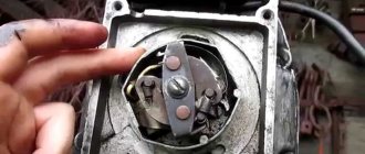
On a new motorcycle (if you were lucky enough to buy one), the contacts, as a rule, are skewed and touch at one point. Using small pliers, you need to slightly bend the contact fastenings so that the area of their contact is maximized. It is more convenient to bend the movable contact hammer; it is more pliable.
After this, the contacts should be cleaned with sandpaper, folding it in half and placing it between the contacts. You don't need to remove a lot of metal. Then the sandpaper should be replaced with a soft cloth soaked in clean gasoline, and the remaining abrasive should be thoroughly removed. After completing this operation, it will not be superfluous to lubricate the axis of the moving contact by dropping 1-2 drops of spindle or motor oil onto it. Apply a few drops of the same oil to the felt felt.
Let's install the breaker with the ignition timing machine in place (don't forget about the mark on the machine's leash!). Now let's adjust the gap between the contacts. Let's set the cam to the position where they are maximally open. Having loosened the screw securing the fixed contact, we will rotate the eccentric with a screwdriver, while simultaneously measuring the gap size with a 0.5 mm thick feeler gauge. When the probe begins to enter the gap with slight friction, carefully close the screw.
Turning the crankshaft using the kickstarter, we will find an arrow on the flywheel (for “Urals”) or a “TDC” mark (for “Dneprs”) and set it opposite the mark in the viewing window.
Now you need to turn on the ignition. Let's take an 8x10 wrench and apply it to the steel core of the coil. We will turn the breaker body in the direction of the arrow stamped on its cover until the key touches the core. In this position, lightly tighten the breaker mounting screws so that it can rotate, but with some effort.
Let's take a long thin rod, for example, an old knitting needle, rest one end of it against the breaker flange, and apply light blows to the second with a small hammer or a 19x22 wrench, thereby slowly turning the breaker in the opposite direction. At the moment the contacts open, the key, attracted to the ignition coil, will fall with a melodious ringing. In this position, the breaker mounting screws must be tightened.
It remains to check that the initial ignition timing we have set is correct. To do this, turn the crankshaft until the contacts close, hang the key on the reel again and, turning the crankshaft with light blows of your fist on the kickstarter, slowly bring the arrow on the flywheel closer to the mark on the crankcase. If the key falls when they match, everything was done correctly. If the arrow does not reach the mark, the ignition is early, and the breaker body needs to be turned slightly in the direction of the arrow on its cover. If the key falls after the marks coincide, turn the breaker in the opposite direction.
At first glance, the amount of work seems quite large. But in everyday use, all operations are not required, and besides, by adjusting the ignition once or twice, you will learn to do this in a matter of minutes, and this system will no longer cause you trouble.
Operating cycle of a four-stroke engine.
As the name suggests, the working cycle of a four-stroke engine consists of four main stages - strokes.
1. Inlet. During this stroke, the piston descends from top dead center (TDC) to bottom dead center (BDC). At the same time, the camshaft cams open the intake valve, and through this valve a fresh fuel-air mixture is sucked into the cylinder.
2. Compression. The piston moves from BDC to TDC, compressing the working mixture. In this case, the temperature of the mixture increases significantly. The ratio of the working volume of the cylinder at BDC and the volume of the combustion chamber at TDC is called compression ratio. The compression ratio is an important parameter; usually, the higher it is, the greater the fuel efficiency of the engine. However, an engine with a higher compression ratio requires fuel with a higher octane number.
3. Combustion and expansion (piston stroke). Shortly before the end of the compression cycle, the air-fuel mixture is ignited by a spark from the spark plug. During the piston's journey from TDC to BDC, fuel burns, and under the influence of the heat of the burned fuel, the working mixture expands, pushing the piston. The degree to which the engine crankshaft (CS) is “underrotated” to TDC when the mixture is ignited is called the ignition timing angle (IAF). Ignition timing is necessary so that the bulk of the fuel-air mixture has time to ignite by the time the piston is at TDC (the ignition process is a slow process relative to the speed of operation of the piston systems of modern engines). In this case, the use of energy from burned fuel will be maximum. Fuel combustion takes almost a fixed time, so to increase engine efficiency, it is necessary to increase the CV as the speed increases. In older engines, this adjustment was made by a mechanical device - a centrifugal regulator acting on a chopper. In more modern engines, electronics are used to adjust the SPD.
4. Release. After BDC of the operating cycle, the exhaust valve opens and the upward moving piston displaces the exhaust gases from the engine cylinder. When the piston reaches TDC, the exhaust valve closes and the cycle begins again.
It must also be remembered that the next process (for example, admission) does not necessarily have to begin at the moment when the previous one (for example, exhaust) ends. This position, when both valves (intake and exhaust) are open at once, is called valve overlap. Overlapping the valves is necessary for better filling of the cylinders with the combustible mixture, as well as for better cleaning of the cylinders from exhaust gases.
From all this we conclude that: 1 - to ignite the working mixture, it is necessary to form a spark on the spark plug; 2 - the moment of spark formation should shift in time depending on the crankshaft rotation speed.
ignition adjustment on the Dnieper
The wire adjustment is as follows: first I adjust the gap on the cams to 0.45 mm (I turn the slider so that the cams open as much as possible). Then I display the letter P (early ignition) on the flywheel, turn the ignition ON and magnetize the key to the coil. I begin to turn the ignition housing all the way slowly but the key and doesn’t fall ((. I set the gap on the cams to different values 0.4, 0.5. 0.6 but the key still doesn’t fall. Help, what’s wrong?
Added: 07/14/2016 18:25:38
I installed the runners from both the old and new models and to no avail. There are sparks on the candles.
2↑ Reply from NIKITA36 07/14/2016 18:39:28
- From: OSTROGOZHSK
- Registered: 25-10-2014
- Messages: 180
- Reputation: 25
- Motorcycle: YES
Re: ignition adjustment on the Dnieper
Why are you so attached to these keys with light bulbs?! Well, if the key does not fall, then the contact does not open - it may have a short to ground, or maybe the cam is not positioned correctly.
And again I am sending a train around the world. I don’t break my hands, I don’t scream out loud. And they won’t impose other people’s passengers on me - I put whoever I want on my train.
3↑ Reply from 16 18:52:46
- Registered: 06-05-2010
- Messages: 6 630
- Reputation: 617
Re: ignition adjustment on the Dnieper
So I don’t understand this masochism. some creature at one time spread this nonsense about keys and light bulbs in the ignition control and people are still suffering.. Roman. If you turn the ignition housing, put it in approximately the middle position. Then you set the crankshaft to the TDC position, and if necessary, use a screwdriver to check through the spark plug hole whether the piston is exactly at top dead center. Next, either use a screwdriver or something else to move the flywheel back a little (not to the front, but BACK), approximately 10mm from the TDC mark. (if you don’t understand, we set the ignition for you earlier).. Then you go and adjust the gap on the cam. gap from 0.4-0.6 mm. If you don’t understand how and where the flywheel is shifted relative to its position at TDC. then you simply adjust the clearance on the cam when the piston is at TDC. It will work 100% But the ignition timing will be slightly different.
Edited 666 (14-07-2016 19:04:43)
4↑ Reply from roman811 07/14/2016 19:32:02
- Registered: 12-06-2016
- Messages: 132
- Reputation:
Re: ignition adjustment on the Dnieper
So I don’t understand this masochism. some creature at one time spread this nonsense about keys and light bulbs in the ignition control and people are still suffering.. Roman. If you turn the ignition housing, put it in approximately the middle position. Then you set the crankshaft to the TDC position, and if necessary, use a screwdriver to check through the spark plug hole whether the piston is exactly at top dead center. Next, either use a screwdriver or something else to move the flywheel back a little (not to the front, but BACK), approximately 10mm from the TDC mark. (if you don’t understand, we set the ignition for you earlier).. Then you go and adjust the gap on the cam. gap from 0.4-0.6 mm. If you don’t understand how and where the flywheel is shifted relative to its position at TDC. then you simply adjust the clearance on the cam when the piston is at TDC. It will work 100% But the ignition timing will be slightly different.
I have TDC and R on the flywheel. When turning the flywheel, the flywheel first goes R and after 10mm TDC. So I set it to P and adjust the clearance on the cams by placing the housing in the middle before that?
Device of contact ignition system.
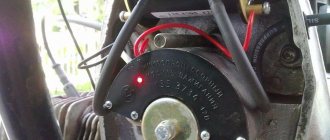
In a classical mechanical safety system, all this is managed by one device - a breaker, a mechanism that determines the moment of formation of high-voltage pulses in the safety protection system of gasoline internal combustion engines. In its classic form, the device includes a low voltage current breaker and a centrifugal ignition timing regulator. The breaker contacts open at a certain moment, breaking the primary circuit of the ignition coil winding (SC), which causes the induction of a high voltage current in its secondary winding. A capacitor is connected parallel to the contacts to reduce sparking. The centrifugal regulator changes the SOP according to the change in the rotation speed of the CV. Let's consider its work using the PM-302 as an example.
The breaker consists of a fixed body with contacts and a capacitor, an eccentric rotor with a centrifugal regulator and a drive fork. The rotor rotates on the nose of the camshaft (CV), but is not rigidly connected to it - the rotor is driven through a drive fork, which is fixed on the flats of the CV. The shape of the eccentric is such that when the rotor rotates, the contacts on the housing periodically (2 times per 1 revolution of the rotor) close and open. The centrifugal regulator, which is a spring-loaded weight on a parallelogram frame, moves the rotor relative to the drive fork as the speed increases, shifting the point of contact opening, and consequently spark formation, which becomes earlier.
This design is quite simple and reliable. however, it has a number of disadvantages: - springs must be carefully selected for uniform operation across the cylinders and the correct SOP schedule. Over time, the springs become deformed, which leads to engine malfunction. It can be eliminated by replacing the springs (a selection of them in pairs is required). — the accuracy of reproduction of the SOP graph is affected not only by the state of the springs of the centrifugal regulator, but also by the state of the return spring of the contact itself, because the rotor eccentric also has to overcome its resistance. This fact is not obvious and is often ignored by many users. — contacts that switch short circuits burn out over time, which leads to a shift in the point of sparking. It can be eliminated by cleaning the contacts and re-adjusting the ignition. To prevent this phenomenon, the contacts must be made of a refractory alloy, which is not done in modern products. — the exclusively mechanical nature of the ignition timing mechanism determines the only SOP schedule, which cannot be changed. Depending on the engine capacity, transmission gear ratios, and operating conditions, this SOP schedule may be far from optimal.
Website about joints
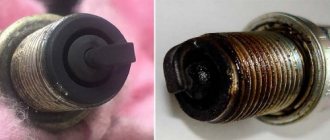
I think on average 100 out of 100 opposition drivers have encountered various engine problems in one way or another related to spark plugs. In most cases, it looks like this - one cylinder stops working, the motorcycle sooner or later stops and the frantic unscrewing-wiping-calcining-twisting of the spark plug begins, or replacing it with one of the huge pile of others lying in the trunk/glove compartment/briefcase. After some time, everything repeats again. Everyone went through this path cursing with the words “This is an opposition baby.”
Is the gap the same for gasoline and gas?
Many car owners install gas equipment on their cars in order to save money. It is important to remember that gas requires other candles. Firstly, a mixture of gas and air ignites much worse than a mixture of gasoline and air, so the spark must be more powerful. Consequently, the load on the ignition coil increases, which can ultimately lead to its failure.
Thus, the interelectrode gap for gas should be smaller, but simply bending the side electrode does not completely solve the problem. The fact is that when gas burns, much more heat is released, because of this there is a high risk of glow ignition. In this regard, the candle should be “colder”, i.e. with a high heat number.
