Reasons for repair
The most popular reason to repair a Ural motorcycle is considered to be insufficient dynamics of the motorcycle, smoke from the muffler, loss of traction at high speeds, and a decrease in maximum speed. Reasons that even inexperienced riders can note include increased fuel and oil consumption. If such problems appear, there is no need to disassemble the engine right away; first you should check the ignition, then the carburetor settings, measure the compression and check the valve adjustment, and after eliminating all other problems, you should get into the engine and repair the Ural motorcycle engine.
You might be interested in how to tune a Ural motorcycle. A detailed description of possible directions for tuning a bike!
More experienced owners may suspect a problem by the sound of the engine. Specific noise reveals a number of problems that are determined with high accuracy.
There are also a number of reasons to repair the engine that are not related to its breakdown. For example, the engine can be rebuilt during a long period of inactivity, during restoration, after a long mileage, and so on.
content .. 11 12 17 ..REPAIR OF MOTORCYCLE ENGINES “DNEPR” AND “URAL”
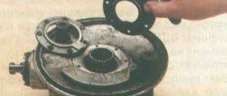
DISASSEMBLY. Let's look at engine disassembly using the example of the Ural M67-36 motorcycle engine. It is carried out in the following order: remove the gearbox by unscrewing the stud nuts and the bolt securing the gearbox to the engine crankcase; disconnect the suction pipe and remove the carburetor with the gasket, the cylinder head cover and its gasket, having previously placed a tray under the connector to drain the oil remaining in the cylinder head cover.
For further disassembly, install the piston in the disassembled cylinder at the top. so that both valves are closed, turn the crankshaft - using a special handle (see Appendix Fig. 2).
Having unscrewed the nuts securing the brackets, remove the rocker arms with the axle brackets, and remove the pusher rods. After this, remove the gasket and cylinder head stuck to the cylinder with a light blow of a hammer on a wooden block or non-ferrous metal mandrel attached to the head. When separating the head from the cylinder, you need to ensure that the gasket is separated. If one part of the gasket comes off along with the head, and the other remains in the cylinder, then use a knife to separate it from the cylinder. When removing heads, especially both at the same time, you should mark the parts so as not to confuse them during assembly.
Having unscrewed the nuts securing the cylinder, gently rock it and gently move it without jerking, so as not to tear the paper gasket, and remove the cylinder.
When removing the piston, use the devices shown in Figure 15.
To remove the pushers with guides, unscrew the locking screws and remove the pushers with guides. Then take out the pushers and mark them so as not to mix them up during assembly.
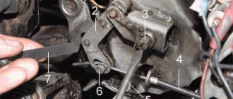
Unscrew the screws securing the front cover and remove it. Disconnect the wires from the ignition coil terminals, remove the breaker cover and remove the high voltage wires along with the rubber bushings. Unscrew the bolt securing the ignition timing automatic and remove it together with the breaker cams. After unscrewing the fastening screws and sliding them with light blows, remove the cover and take out the breather. If the gasket is damaged, it is removed. If it is necessary to inspect and disassemble the lube bypass valve, keep in mind that it
strictly calibrated for pressure in the lubrication line of 70...90 kPa.
Before removing the camshaft, measure the engagement gap and the end runout of the timing gears. To do this, unscrew the mounting nuts and remove the generator. Install the device on the upper right threaded hole and measure the lateral clearance in the meshing of the gears, which should not exceed 0.3 mm (Fig. 31). If the gap is increased, the gears are replaced. Attach the device to the right threaded hole (Fig. 32) and measure the end runout of the gears, which should not be more than 0.04 mm.
To remove the camshaft, remove the flange mounting screws through the holes of the driven distribution gear. To remove the shaft, use a drift and hammer (see Fig. 21) or a special mandrel-puller,
which is inserted into the hole of the removed intake valve guide sleeve of the left cylinder. By bringing the mandrel under the camshaft cam, by turning it, press out the shaft and remove it from the crankcase.
Before removing the flywheel, bend the lock washer of the flywheel bolt and install a 19x22 wrench in the spacer between the hole for the spring in the flywheel and the boss under the engine crankcase mounting stud. Using a key, unscrew the flywheel mounting bolt, remove the lock washer and remove the key. Fix the device (see Fig. 19, a) on the flywheel and, screwing in the central screw of the device, remove the flywheel from the crankshaft cone.
To remove the crankshaft from the crankcase, first remove the drive gear (see Fig. 19.6) and remove the key. Before removing the crankshaft, unscrew the bolts securing the front bearing housing, remove the washers and cover, then unscrew and unscrew the bolts securing the rear bearing housing, remove the washers and rear bearing housing (Fig. 33, a) and press the crankshaft out of the front bearing with a puller (Fig. . 33.6). After this, turn the crankshaft in the engine crankcase with your left hand until it stops, lifting it up, and with your right hand move the connecting rod towards the left hole of the crankcase and remove the crankshaft from the crankcase. If inspection and replacement of parts are not required, the front bearing housing is not removed.
The bearing is removed from the crankshaft rear journal journal using a puller. If the bearing has been removed from the crankshaft journal along with the rear housing, then the bearing is pressed out using a manual press using a mandrel. If necessary, press the front housing with the bearing out of the crankcase and then the bearing from the front housing using a hand press, using a mandrel and a ring.
For Ural and Dnepr-12 motorcycle engines, after removing the crank mechanism from the crankcase, measure the radial clearance in the lower head of the connecting rod with an indicator; it should not exceed 0.1 mm. If the gap is larger, the crank mechanism must be disassembled.
For the Dnepr K-650, MT-9 and MT-10-36 motorcycle engines, unscrew the centrifuge mounting bolt, remove the washer, as well as the paper and rubber gaskets, and screw a plug tip into the hole in the end of the crankshaft. Remove the centrifuge body with the lid using a universal puller (Fig. 34). Disconnect the lid from the centrifuge body and remove the screen. The remaining operations are similar.
To remove cylinders from K-750 engines, remove the screws securing the valve box covers, remove the covers and their gaskets. Unscrew the cylinder fastening nuts and carefully remove the cylinders with valves and gaskets. Then remove the pistons, pushers with guides and the generator. Remove the front crankcase cover, move the breaker cover holder with the strip aside, and remove the distributor cover. Unscrew the rotor mounting screw and remove it from the camshaft. The further process of disassembling the K-750 engines is not difficult.
After disassembly, the parts are washed, cleaned of carbon deposits, carefully inspected and the necessary measurements taken. If necessary, worn parts are replaced or repaired.
content .. 11 12 17 ..
Choosing a case that suits your needs
Having set the goal of tuning a Ural motorcycle with your own hands, it is important to understand that there are modifications that are relatively painless and do not require documentary evidence to register the vehicle and undergo a technical inspection.
And there are changes that, in order not to conflict with the law, must be agreed upon with the manufacturer or other regulatory authorities. Based on this, tuning for a Ural motorcycle should be divided into two categories:
We will consider each of these categories separately.
Motor defective
The process of disassembling the motor is quite complicated, but what is more important is that the existing gaps “go away.” Thus, if you disassemble the motor and then reassemble it without repair, extraneous noise is likely to appear due to the increase in gaps. Therefore, experienced mechanics advise, first of all, to assess the condition of the motor without disassembling the main elements, or to carry out a partial disassembly, then carry out troubleshooting and, based on its results, decide whether to make repairs or not. A malfunction can be determined “by ear” if:
Reason: wear of the piston pin and the appearance of an excessively large gap between the pin and the bushing. Solution: first of all, you can set the ignition later, in some cases this either completely eliminates the noise, or it becomes insignificant, which allows you to use the motorcycle for some time. If this does not help, then the old pins are replaced with new ones, as well as the connecting rod bushings with their subsequent development.
Reason: the appearance of a gap between the pin and the piston boss. Solution: replace the pin + piston set with new ones of the same group.
Reason: clearance between piston and cylinder. Solution: selecting a new piston of the next repair size and boring the cylinder for a new piston group.
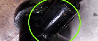
Reason: This sound may indicate an increase in the gap between the lower end of the connecting rod and the crankshaft crank pin.
By the behavior of the motorcycle you can find out about the following problems:
Cause: worn piston rings. Solution: complete replacement of the piston rings, and if there is damage to the cylinder plane, boring it, with subsequent repairs.
Owners of the Ural motorcycle most often encounter similar problems. As you can see, most problems are diagnosed by craftsmen “by ear”, and despite all the primitiveness, the result turns out to be very accurate. Assuming there is a problem with the motor, you should stock up on a set of necessary pullers, keys and repair parts, and only then begin disassembly.
A little history
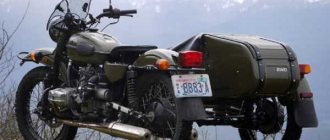
The products of the Irbit Motorcycle Plant are well known not only in our country. Various models, whose design originates from the pre-war BMW R71, have retained their parental genes for seventy years. True, the prefix “Ural” appeared in their name a little later. Since 1961, it has been assigned to the following modifications:
Next, it was decided to limit ourselves to the name Ural, removing the additional digital index and leaving only the factory designation.
And this is not counting special versions and limited editions. But in the process of tuning a motorcycle, any of the listed modifications have a lot in common. Despite the changes in the name, all models are similar in design and have similar technical characteristics.
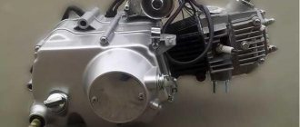
Assembly of a 2022 URAL 750cc motorcycle engine
In this article I want to share information on the assembly of the Irbit Motorcycle Plant (IMZ) Ural 750cc engine, modification 2019 :), but a carburetor version, although carburetor ones are not produced now, the only difference is the camshaft and the front timing cover, so I think it will be normal. There may be an injector in the future.
At the moment we have the following spare parts:
- Crankcase
- Crankshaft
- Camshaft
- Timing gears
- The oil pump is model 2010-2018 (later I will replace it with a 2019 one, they say the performance has been increased and the oil intake is designed differently).
- Front, rear crankshaft support
- Pallet model 2022
- Bearings
- Gaskets
- Hairpins
- Timing cover
Everything was basically bought during 2018-2019 from official representatives, I won’t give prices, I managed to find something cheaper, something more expensive, but everything was from the IMZ plant.
The entire piston has also been ordered:
- 2022 model cylinders
- Pistons
- Rings
I'm waiting for it to arrive from the factory. This will be discussed in the next article.
Let's start assembly. In general, the first step is to install an aluminum tube into the front mount of the engine crankcase, install the rubber seals and flare this tube.
But it fits into the hole by hand, and I left this matter for later.
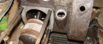
Install the front crankshaft support. To do this, heat the mounting hole in the crankcase with a hairdryer/torch.
Once warmed up, install the front support. Because the landings have not yet been gouged out, I needed a mallet, we combine the holes on the crater and on the support, and with light blows, with a mallet we upset the support itself and at the same time tighten the bolts so that the support does not move out.
We place the bolts on the thread lock and tighten them.
Next you need to prepare the crankshaft for installation. To do this, you first need to install the bearing on the front axle. The crankshaft bearings in this engine are 6208. I used FAG. Lubricate the bearing seat with a thin layer of oil, and then you need to slightly warm up the inner race of the bearing.
We position the bearing on the crankshaft so that there are no distortions, and using a suitable mandrel, with light blows, we seat the bearing.
It turned out like this
The next step is to install the crankshaft of the Ural engine into the crankcase. To do this, we orient the crankshaft so that the flywheel keyway faces upward, tilt the shaft with the rear shank down and lower it into the crankcase. We direct the connecting rods into their cylinder bores and install the crankshaft in the correct position, directing the front bearing into the front support, without distortions, since there is a possibility of damaging the bearing or the front support itself.
Next, to pull the crankshaft into place, you need to use a special puller. I used a pulley puller, the cheapest one, you can also cut out a 4mm steel plate and drill one hole in it in the center. Unfortunately, I didn’t photograph the process... In general, through this plate or puller we pass a bolt with an M8 thread, pitch 1.25. We install the puller and screw the bolt into the crankshaft, while the puller must be resting through some spacers against the crankcase so that the crankshaft moves forward. And we begin tightening, but before that, of course, we lubricate the support with oil. Next, the main thing is not to overtighten, you need to control the position of the crankshaft through the holes for the cylinders, and watch the oil catcher so that it does not rest against the crankcase and bend. I didn't do this and bent it a little. It will be a lesson