How to check the serviceability of the generator on a Ural motorcycle. Ural motorcycle generator how to check
Checking and adjusting the G-11 A generator of the Ural bike can be done using various methods.
Serviceability is monitored by a warning light, and if for any reason it is missing or burnt out, then it is necessary to remove one of the wires from the battery terminal at medium engine speeds. If the engine continues to run, it means the generator is working. The generator can also be checked by connecting one end of the wire to a portable lamp to ground, and the other to terminal I of the relay regulator (in this case, the wires must be disconnected from terminals Ш and И). Then give the engine medium speed, and if the portable lamp glows, then the generator is working.
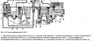
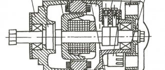
1 - drive gear; 2 — oil seal; 3 - armature winding; 4 — front cover; 5 — body; 6 - wooden wedge; 7 - armature core; 8 - pole boot; 9 — excitation winding; 10 — brush; 11 — brush spring; 12 — contact bolts; 13 - ball bearing; 14 — bearing cover; 15 - coupling bolt; 16 — armature shaft; 17 — brush holder; 18 - collector; 19 — cover; 20 - protective tape.
Characteristics of the G-11 A electric generator → more details.
Adjusting gear mesh
If the generator has been removed, then when installing it in place it is necessary to adjust the engagement of its drive gears.
The procedure for adjusting the G-11 A generator of the Ural motorcycle is as follows:
— install into place in the engine crankcase;
— start the engine and listen to the noise the drive makes;
— if the drive is noisy, you need to increase the gap between the gears;
— and if you hear a knock, reduce the gap;
— loosen the bolt of the tightening tape and, turning the generator by the housing, set by ear the required gap between the gears;
— secure the tensioning tape and check the noise of the gears again.
MY MOTORCYCLE
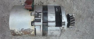
“Ural” 500-watt generator No. 14.3771 - the unit is excessively noisy and not very reliable. But oppositionists, having tasted the charm of powerful light and forgotten about discharged batteries, prefer to put up with its shortcomings. And not to change it, but to repair it. In general, this is not difficult to do. And this material will touch precisely this topic.
First, remove the rectifier cover by prying it off with a screwdriver. If this is done carefully, the latch antennae securing it will not break. But later we recommend screwing an M5 nut onto the protruding ends of two opposite tightening bolts - it’s more reliable. Then unscrew the two screws securing the relay-regulator and carefully remove it complete with the brush assembly. The relay-regulator YA212A11E itself fails extremely rarely, but if this happens, know that in addition to the original one, similar -36.3702 or 361.3702, used on generators of Vladimirets tractors and modern Volgas with a ZMZ 406 engine, will be suitable. The differences between them are in the level of charging voltage: 36.3702 -14.2 V. and 361.3702 -14.4 V. Higher voltage is useful at low temperatures and frequent short trips with light. During normal use, the “stepson” will cause a slight reduction in battery life.
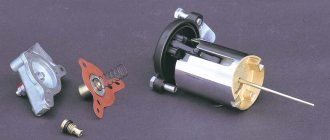
1. Unscrew the castle nut securing the gear. This is not as easy to do as it seems at first glance - there is no flat on the rotor that you could grab with a key. The problem can be solved with the help of large pliers (hold the base of the gear, not the teeth!). When assembling, place a copper or brass washer under the nut - this will protect its threaded part from loosening.
2. The gear, as a rule, sits on the shaft with some interference. To remove it, you can use a universal puller or two open-end wrenches “22”, as shown in the photo. And when assembling, heat the gear to about 100 C (throw it into boiling water for half a minute) - and it will sit on the shaft “by hand”. Then remove the thin steel washer from the shaft, use a small screwdriver to remove the rubber ring from the inner groove of the sleeve and remove the sleeve from the shaft by removing it from the oil seal
3. Using a size 8 wrench, unscrew the four nuts of the coupling bolts and remove the rear cover of the generator complete with stator and rectifier. Further, if the reason for the repair was a malfunction of the stator (this, by the way, is not uncommon), it will have to be separated from the cover. To do this, you need to unsolder three phase terminals from the rectifier terminals. It is unlikely that you will be able to find a “native” stator on the market. Rewinding the old one is, in principle, not difficult, but this should be done by a professional. There is a way out of the situation, but with the condition that you completely accidentally ended up with a generator 18.3771 or 181.3771, used on tractors from the Vladimir plant. Its stator is the same size, but with a slight design difference. To install it on our generator, you will need to trim the front and rear housing covers on the stator side by 6 mm on a lathe. After such a replacement, the current generated by the generator at high crankshaft speeds will increase to 55 A, but at low speeds, on the contrary, it will decrease. The generator will be excited only from 1100 instead of the usual 750 rpm
4. If the reason for the repair was only a faulty stator, you can proceed with assembly (by the way, in this case there is no need to remove the gear). When installing the coupling bolts, make sure that their heads fit into the shaped cutouts all the way. In some cases, for reliability, they can be slightly hammered.
5. Let's continue operations with the rotor remaining in the front cover. Having installed the cover on some supports, apply several gentle blows to the shaft with an aluminum or copper hammer, while the rotor will be pressed out of the front bearing (you can use a regular hammer and a soft metal spacer). Next, unscrew the four screws from inside the cover, remove the flange, spacer ring and remove the bearing
6. Look what happened. Engine oil that has leaked through the seal will flow through the bearing and wash away the grease from it. This is why that same squealing sound appears, so familiar to the owners of our generators. We will still fight this irritant. In the meantime, replace bearing No. 180503. In addition to the 500-watt generator, it is used in the G-502 generators from Zaporozhets, 26.3771 in some Zhiguli models, as well as in the already mentioned tractors, so finding it won’t be difficult!
7. Our task is to remove oil from the bearing if it leaks (it cannot avoid leaking at all). Remember the rear axle collar seal and the technical solution used there to drain oil. Let's try to “depict” something similar and, using, for example, a drill, we will gnaw through a groove connecting the cavity between the oil seal and the bearing with the internal cavity of the generator. Such modification will not weaken the bearing fit, but we will achieve the desired effect. If necessary, replace the oil seal (its size is 11x22x40).
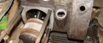
8. Rear bearing No. 180502 fails much less frequently. But if you feel noticeable play in it, change it. This is not easy to do; the flats are narrow, like the flats on a plastic ring, and not every puller can grab hold of them. You can get out of the situation with the help of curved pry bars, acting with them as shown in the photo.
9. On generators of early releases, the same defect quite often arose - a break in the excitation winding. Subsequently, it was managed to be eliminated almost completely. The “old” rotor is distinguished by a thread for the M12x1.5 nut (versus M12x1.25 for the “new” one) and the fact that the rear end of the shaft does not protrude beyond the level of the slip rings (the “new” rotor has a shaft at the rear for support when pressing on the front bearing ). As a rule, a break occurs not in the depths of the winding, but at the point where its output is attached to the rear slip ring. The location of the defect, as well as the method for eliminating it, are illustrated in the photo.
When assembling, pressing the front cover with the bearing onto the rotor shaft, do not forget to first put the spacer sleeve on the shaft. It is a good idea to lubricate the rubber ring located under the gear in the groove of the sleeve with sealant before installation. Before putting on the back cover assembled with the stator, wipe the rotor contact rings with alcohol or solvent; in case of severe contamination, they can be lightly cleaned with fine sandpaper. R.S. If you don’t know a dentist who can help you purchase a used drill, don’t despair. As a last resort, sharpen the hacksaw blade with a sharp hook and manually dig out the oil drain channel.
Source: MOTO magazine
Generator G-424
To understand the principle of operation of the generator and relay regulator, a little theory.
Electric generator G-424 is a three-phase machine, with electromagnetic excitation. Generates alternating current. VGB-2A rectifier converts current into direct current. For normal operation of an electric machine, a relay-regulator PP-330 . The job is to regulate the voltage of the motorcycle's on-board network so that it does not exceed 14 volts.
The G-424 generator is not able to work with a discharged battery. To start the engine and increase to 2400 rpm, the motorcycle runs on a battery. Only after this threshold is exceeded does the electric generator operate in self-excitation mode.
Generator G-424 is PROHIBITED to be turned on without load!
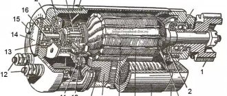
Generator circuit G-424: 1 - cover; 2 — oil seal; 3 - rotor; 4 - stator winding; 5 - terminal block; 6 — back cover; 7 — shield assembly; 8 - rectifier block; 9 - fan; 10 — protective casing; 11 - bearing.
Troubleshooting the generator
The method for determining the malfunction was as follows (I tried several methods, since replacing the relay regulator did not help):
Indirect determination of generator performance
This method does not allow you to accurately determine the malfunction of the generator, but it can still be used to determine whether the generator is “dead,” or there is still hope and the cause of the malfunction lies elsewhere.
Disconnect the wire from terminal “Ш” on the generator. And we apply + from the battery to this terminal, bring the wrench to the generator body, it should be magnetic, not much, but it is noticeable. If it is magnetic, then the rotor winding is working properly. Turn it off.
We connect a 12 volt lamp to the “+” terminal on the generator, and the other end of the lamp to ground. And we connect “+” from the battery to the “Ш” terminal. And we turn the engine with the kickstarter, the light should light up. If this happens, then the generator is working.
In my case, the light was on, I changed the relay-regulator, but the battery still did not charge, and when the engine was running, the red battery charge control light did not go out.
Cleaning and testing the generator G 424
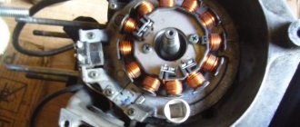
- I removed the generator, unscrewed the back cover, pulled out the brushes - the wear was within normal limits, they were checked with a multimeter.
- Using the probes through the windows for the brushes with a multimeter, the armature rang - “it rang”, there is no short circuit to the generator housing.
- I unscrewed the rectifier and it “ringed” like diodes, i.e. In one direction the arrow should deviate, I change the polarity, the arrow does not deviate. Those. the diodes are not “broken”, as they should be.
- I rang the stator windings - everything is normal, there is no short circuit to the housing.
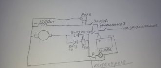
Connection diagram for generator Ural 4320 with relay voltage regulator
Bibliographic link to the article:
// Modern equipment and technologies. 2012. No. 3 [Electronic resource]. URL: https://technology.snauka.ru/2012/03/310 (access date: 04/12/2021).
Ph.D. tech. Sciences Gumelev V.Yu.,
Ph.D. tech. Sciences Kartukov A.G.,
The Ural-4320-31 car is one of the main brands of military automotive equipment (VAT) used in the Armed Forces of the Russian Federation.
The readiness to use vehicles is largely determined by the technical condition of the electrical equipment, and primarily by the power supply system. The power supply system includes sources of electrical energy: the main one is a generator set; additional – batteries. When the engine is running, the generator must provide power to the vehicle's power receivers and charge the batteries. The relay regulator consists of one regulatory element - a voltage regulator.
A generator with a voltage regulator forms a generator set. The Ural-4320-31 vehicle is equipped with a generator 1702.3771 or G 288E [1]. The non-contact voltage regulator 2712.3702 is used to maintain a constant voltage in the vehicle's electrical network. It is an electronic device with 3 silicon transistors, unshielded, dust-splash-proof. The voltage regulator is installed under the hood of the URAL-4320-31 car on the front panel of the cab.