Our company is committed to protecting your confidential information. Our privacy policy explains what information we collect about you, how we use the information we collect about you, and how you can tell us if you would prefer to limit the use of such information.
By providing your information you consent to the use of such information in accordance with this privacy policy. If we change our privacy policy, any changes will be posted on this page without notice.
What kind of personal data do we collect about you?
We collect information about users of our website in a number of ways, including through the use of log files stored on the client's system, through registration, and through email messages sent to us through our website. The information collected includes the following: If you send us an email, you will automatically provide us with your mailbox address as well as other personal information included in the body of your email.
If you call our technical support center or leave a voicemail, you agree to provide us with your name, contact phone number(s), your email address, and any other personal information that you agree to provide to our technical specialists in order to so that our technical specialists can respond to your request.
We collect and store information from all visitors to our website that they either actively provide to us or through their mere browsing of our website: computer Internet Protocol (IP) address, browser type, operating system type, date and time of access to our website, address of the Internet resource from which the user was redirected to our website. We use such information to track traffic to our website, count the number of visitors to different sections of the website, and to make our site more useful.
Garage
I had a wonderful motorcycle Zizer 400 -98. And one day this happened: after riding, I drove to a gas station and filled the tank full. It’s already dark outside, I go to the motorcycle, look at it, my eyes are happy, my emotions are overwhelming. I sit down, press the starter and figs - there’s some kind of crackling noise, the starter doesn’t turn. I called my friend, explained the situation, he said he would come. I'm waiting, sir, I arrived in about 10 minutes. We didn’t think long about it, it was too late to get to the garage 1-2 km away, so we decided to try to start it with a pushrod. It started up with a bang from the pushrod, but the headlight does not light up. I drove without a headlight, fortunately my comrade was driving ahead and had his headlight on.
Video for those interested. (you don't have to watch it :))
It was night outside, I didn’t bother to rack my brains, I stomped home with heavy thoughts. The morning is wiser than the evening. The next day I went to the garage to solve the problem. I started dancing from something simple. We diagnose fuses. I checked. They turned out to be all intact.
I took a photo of the fuse box in the garage.
I decided to start the horse again, and oh mystic horror... the starter spun, then silence. Then a neighbor in the garage came, we don’t leave our own people in trouble. The neighbor came not empty-handed, but with a multimeter. I measured the voltage on the battery and it read 10V. Dead acc, such a bastard.
I took this parasite home and put it on charge. It took three hours to charge. brought it to the garage. I installed the acc, and yay - the engine started up BUT the headlight does not light up
Okay, I think I got burned. In general, the battery charge was enough for three engine starts. I put it in the garage to charge, the voltage is low, charging will take a long time. In order not to waste time, I went to inspect the connectors and terminals for melting/oxidation. Everything is clean everywhere - makes me happy!
I flew to the store, bought a new light bulb, inserted it into the socket without putting on the muzzle - it lights up, hurray, hurray, hurray. And then my natural curiosity takes over, let me think, I’ll put the old one on, check for lice, so to speak... /drumroll/, the same thing - it’s burning O_o Profuse sweating and mental circulation began. I asked my neighbor to measure the voltage with the engine running at 4000 rpm, it showed 14V, which means the generator is working and I’m happy. “Perhaps there is a short circuit, a short circuit somewhere? “, I say to my neighbor. He advises checking using the old-fashioned method - we remove one terminal from the aka. We put a light bulb between the terminal and the cable, turn the key to the ON position and the light comes on. “It’s not short,” says the neighbor.
I decided to buy a new battery since there was such a binge. As in the song: walk, walk. Bought. Now it starts normally and the horror of mysticism continues to repeat itself, now the headlight is on, now it is not. Started it - it lights up. Turned it off. Turned it on again and it no longer lights up. After several tests it stopped starting again, rattling noise, sweating, mental disturbances (I already have the last one).
Video to break up so much text:
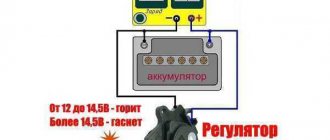
Now it’s the turn of my dear relay regulator (RR)
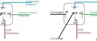
The manual has several ways to check PP:
Method 1: The lamp should not light on more than one terminal. It lit up happily at terminal Y3. My sadness knew no bounds
Go ahead. Method 2:
Here, too, the lamp should not be lit. Again on Y3 it lit up for me. There is no point in continuing further. RR is dead. It is a thankless task to revive, because it is difficult to disassemble and after tearing apart this rubber casing, it is stupid to change the burnt out parts, it is easier to buy a new one.
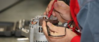
But we save money and fight for reliability by not following simple paths. It was decided to solder the relays on our own. There is only one BUT - I can solder two wires together, and anyone who sees my “work” will cry. I started looking for friends who could do this. And such a person was found, we agreed on 2000 rubles
While the relay was being manufactured, it was boring and I decided to check the operation of the generator not in an indirect way (at the speed of the operating engine), but according to science. The alternating current was measured on a connector suitable for the RR. On all pairs of contacts (the chip that plugs into the RR) 42-44 volts were knocked out... The great manual assures that ideally it should be 45... people claim that 44 is also cool, and I believe it. We attribute it to the error of the device and the age of the motor . The result: the generator is alive, it’s proven!
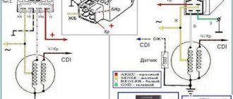
RR scheme
Details:
1) Radiator, the bigger the better 2) 36MT120, 3-phase bridge 36A 1200V - 1 piece 3) ULN2003A PBF DIP16 - 1 piece 4) BZX55C13, zener diode 13V, 0.5W - 1 piece (I will solder 14V for myself) 5) BTA26-600B PBF TO218 - 3 pcs 6) K10-17Bimp. 1000pF NPO, 5% -1 piece 7) S2-23 0.5 W, 5%, 300 Ohm -4 pieces
THE DETAILS ARE JUST LIKE THIS. NO ANALOGUES, SUBSTITUTES, ETC.!!!
In terms of color we are talking about zzr 400 - 1998. On other motorcycles to which this PP will also fit, the color may and most likely will be different!
WHITE wire on the motorcycle “+” BLACK WITH YELLOW STRIPED wire on the motorcycle “-” THREE YELLOW - “phase”. The BROWN wire on the motorcycle is the “key” and can be insulated.
This means there will be five wires from the RR, the positive one naturally connects to the positive one on the motorcycle. Negative from a negative relay on a motorcycle. Three phases from a relay with phases on a motorcycle, the order of connecting the phases does not matter, there is alternating current. Therefore, the phases do not matter which wire is connected to which. It seems like everything is wired...
Materials on RR taken from the site
A week later, the RR is ready, the only thing is that they did not fill this structure with silicone, first check for functionality.
We installed a zener diode at 13v. Now check. At 4000 rpm, the battery charge was 13.3-13.5. Charging is, in theory, normal and not worth worrying about. But I still decided to solder a 14V zener diode so that the charging would be about 13.8-14.2V. The manual echoes everyone who reads it: charging must come
The RR heats up quite strongly, after 4 minutes on the choke (4000 rpm) the hand cannot hold it. After soldering in a 14V zener diode, it will clearly heat up more, and this despite the fact that the size of the radiator is clearly larger than the original. I don’t want to take risks, I’ll do the cooling, take care, as they say...)
Soldered in a 14V zener diode. The lamp is on, everything works. I don’t like the collective farm, I like it to be all right. Usually, when making RRs, people solder wires directly into the device, bypassing the chip (remember the connector on which I measured the voltage from the 42-44V generator). I asked the person to install a connector from the old RR. No sooner said than done.
The person who dismantled the old RR said that there were burnt parts in the 3rd phase (at that time the lamp still came on when checking the RR). It turns out that the discharged battery killed RR, sad thing.
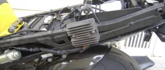
I'm starting to put RR. It will not be possible to stick it in its original place; the radiator dimensions are larger than the stock one. We remove the seat, fortunately we only need to unscrew two bolts. We take a couple of clamps (silicon, it seems) and attach them to the tail. RR must be circuit-based - a mandatory requirement for me.
Now we install cooling. I bought a fan 80 from Zalman. It's a bit big in size, but it cools very quickly. “+” of the fan goes to the brown wire, “-” to the black and yellow one. To prevent the fan from becoming clogged from a sudden power surge, we install a stabilizer “KREN-5” or 8, I don’t remember exactly. It turns out that it was possible to buy a stabilizer immediately in an insulated housing, which I found out about after finishing the work.
That's how it is, guys.
PS: This RR is suitable for different motorcycles. It absolutely fits the Susa RF400, and many other models, I can’t say for sure, but it seems even 600 cc.
What do we do with the information we collect?
We use personal data to provide you with the services you ask us to provide. Unless you notify us that you no longer wish to receive this type of information, we may provide you with periodic communications about our products and services. By providing us with your personal information by email or telephone, you consent to our use of your information in the manner described in this paragraph.
We may conduct statistical analyzes of user behavior (for example, by analyzing website usage data collected passively from all users) to determine the relative degree of consumer interest in different areas of our website. Such analysis will help us in our efforts to further improve the product.
In what cases can you ride a motorcycle without a regulator relay?
It is not recommended to drive without a regulator relay. However, there are situations when it fails. It takes a lot of time to restore it. Therefore, many motorcyclists do not wait for repairs and risk going on trips without this device.
Experts are skeptical about such risky trips and recommend driving without a regulator relay if:
- the battery has an absolutely full charge level,
- The battery is in perfect working order,
- The relay regulator must be in the off state.
Connection diagram for the VAZ-2109 generator
- Alternator. The 37.3701 or 94.3701 series can be installed.
- Negative diode.
- Additional diode.
- Positive diode.
- Alternator warning lamp, also known as battery discharge lamp.
- Instrument cluster.
- Voltmeter.
- Relay and fuse box located in the engine compartment in the compartment between the engine and the vehicle interior.
- Additional resistors built into the fuse mounting block.
- Ignition relay.
- Egnition lock.
- Accumulator battery.
- Capacitor.
- Rotor winding.
- The voltage relay is located in the engine compartment.
Connection diagram for the VAZ-2107 generator
1 - battery; 2 - negative diode; 3 - additional diode; 4 - generator; 5 - positive diode; 6 - stator winding; 7 - voltage regulator; 8 — rotor winding; 9 — capacitor for suppressing radio interference; 10 — mounting block; 11 — battery charge indicator lamp in the instrument cluster; 12 - voltmeter; 13 — ignition relay; 14 - ignition switch.
—>Auto parts and service stations —>
Contact terminals (terminals, plug connectors, etc.) of generating sets of different models, years of manufacture and manufactured by different electrical manufacturers may have different letter, number or symbol designations.
At the same time, not only a novice auto electrician or mechanic who is inexperienced in repairing on-board electrical network systems of cars, but even an experienced electrical equipment repair specialist may encounter unfamiliar designations, which can lead to unpleasant technical consequences during repairs and diagnostic checks of the generator. For those who are engaged in diagnosing and repairing electrical equipment only of domestic cars, it will not be difficult to remember the not so extensive list of symbols on the terminals of generators, but the contact connectors and terminals of generators of foreign cars often contain many unfamiliar symbols. It should be taken into account that sometimes the terminals and contacts of generators from individual manufacturers may have the same letter designation with different functionality.
Table 1 shows the most common designations of electrical contacts and terminals of generators, both domestic and foreign.
Table 1. Designation of contact connectors and terminals of generating sets
Click on image to enlarge
Below is an additional list of designations that may not have been included in the table above:
A - same as IG plus battery;
AS (Alternator Sense) - the same as S - battery plus;
B+ battery - (+) battery plus;
B- battery - (-) minus battery;
BVS (Battery Voltage Sense) - the same as S - battery plus;
C (Communication) control input for the voltage regulator of the engine control unit. When applied to this input, the voltage at the generator output will not exceed 12.5 V;
COM (Communication) is a general designation for the physical interface for control and diagnostics of the generator. BSD (Bit Serial Device), BSS (Bit Synchronized Signal) or LIN (Local Interconnect Network) protocols can be used; prefix aRCI 011;
D+ - terminal (+) of an additional diode bridge to power the voltage regulator. Serves to connect an indicator lamp that supplies the initial excitation voltage and indicates the operation of the generator; the indicator lamp;
D (Drive) — regulator control input with PD terminal; attachment aRC-011 or VRT-RC;
D (Dummy) - empty, no connection, mainly on Japanese cars;
D (Digital) - voltage code input on American Fords, the same as SIG;
DF - same as F external regulator;
DFM (Digital Field Monitor) - same as FR; attachment aRC-011 or VRT-RC;
E (Earth) “earth”, battery (-);
F ( Field ) — voltage regulator output external regulator;
FLD - same as F external regulator;
FR (Field Report) - output for monitoring the load on the generator by the engine control unit;
G (Ground) - same as C;
I (Indicator) - the same as L control lamp;
IG (Ignition) - ignition switch input plus battery;
IL (Illumination) is the same as L control lamp;
L ( Lamp ) — output to the lamp of the generator performance indicator; control lamp;
LI (Load Indicator) - the same as FR, only the signal is inverted;
LIN direct indication of the control and diagnostic interface of the generator via the LIN (Local Interconnect Network) protocol;
M (Monitor) - same as FR;
N (NULL) - output of the midpoint of the stator windings. Typically used to control the health indicator lamp of a generator with a mechanical voltage regulator;
N/C (no connect) - no connection;
P (Phase) output from one of the generator stator windings. Serves to determine the excited state of the generator by the voltage regulator;
RC (Regulator Control) - same as SIG;
RLO (Regulated Load Output) - voltage control input for stabilizing the regulator in the range of 11.8-15 V (Toyota)
RVC (L) (Regulated Voltage Control) - similar to SIG;
S (Sense) - sensor, input for comparing voltage at the control point. Typically the test point is in the fuse box closest to the battery (CHARGE fuse) plus the battery;
S (Stator) - same as P;
SIG ( Signal ) — voltage code input;
STA (Stator) - same as P;
Stato r - same as P;
W (Wave) - output from one of the generator stator windings for connecting a tachometer in cars with diesel engines;
15 - the same as IG plus battery;
30 - the same as B+ plus battery; ; 31 - same as B- minus battery4
61 - the same as L warning lamp;
67 - same as F.
Addition: P, S, STA, Stator, R Phase/Stator output from one of the generator stator windings. Serves to determine the excited state of the generator by the voltage regulator
Source
Connection diagram for the VAZ-2101 generator
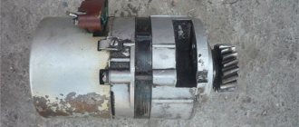
Structurally, generator 2101 consists of the following main elements:
- The rotor is a moving part that rotates from the engine crankshaft. Has an excitation winding.
- The stator is the stationary part of the generator and also has a winding.
- Front and rear covers , inside of which bearings are installed. They have eyelets for attaching to the internal combustion engine. The back cover contains a capacitor necessary to cut off the alternating current component.
- Semiconductor bridge - called a “horseshoe” for its similarity. Three pairs of semiconductor power diodes are mounted on a horseshoe-shaped base.
- A pulley on which the VAZ-2101 generator belt is placed. The belt is V-shaped (on modern cars a multi-ribbed belt is used).
- The voltage regulator is installed in the engine compartment, away from the generator. But still it must be considered part of the structure.
- The brushes are mounted inside the generator and transmit the supply voltage to the field winding (on the rotor).
Pre-check
To check the generator voltage regulator you will need a multimeter. We start the engine and measure the generator voltage with a multimeter. We connect one probe of the measuring device to terminal 30 of the generator (the same pin on the rear wall of the generator, to which there are usually two, sometimes three wires and secured with a nut). The voltage should be between 12.5 - 12.8 volts.
Then we start the engine and again measure the voltage at the generator terminals. At idle there should be at least 13.2 volts, but not more than 14 volts. Then we increase the engine speed to 3500 rpm, in this case the voltage limits should be within 14.2 - 14.5. The voltage should not exceed 14.8 volts. If it is higher, then the battery is being recharged.
Then we turn on the high beam headlights, heater, hazard warning lights and other devices and again measure the voltage at the generator. It will drop under the load of switched on devices, but the voltage value in this case should not be lower than 13.2 volts. If it is below the minimum - “undercharging”.
In both cases, it is necessary to check the voltage stabilizer.
Connection diagram for the VAZ-2110 generator
On VAZ-2110, 2111 and 2112 cars, a 94.3701 generator was installed with a maximum output current of 80 Amperes and a voltage = 13.2–14.7 Volts.
Here is a breakdown of the connection diagram for the generator on the ten :
- Battery 12V;
- generator 94.3701;
- mounting block;
- egnition lock;
- battery charge indicator lamp in the instrument cluster