During the operation of a car, problems with the battery and generator often arise. Often, the battery may fail due to insufficient charge. This problem is relevant both for many foreign cars, especially with mileage, and for various domestic cars (VAZ, GAZ, ZAZ, etc.).
For normal operation of a car battery, it is necessary that the generator charges the battery while the engine is running, and neither undercharging nor overcharging of the battery is allowed. Next, we will look at problems with battery charging using the example of a VAZ 2106, the charging relay on this car model, and also how to check the VAZ regulator relay yourself.
Purpose of the voltage regulator relay
Regardless of experience and driving style, the car owner cannot ensure the same engine speed at different times. That is, the crankshaft of the internal combustion engine, which transmits torque to the generator, rotates at different speeds. Accordingly, the generator produces different voltages, which is extremely dangerous for the battery and other consumers of the on-board network.
Therefore, replacing the alternator regulator relay should be done when the battery is undercharged or overcharged, the light is on, the headlights are flashing and other interruptions in the power supply to the on-board network.
Interconnection of car current sources
The vehicle contains at least two sources of electricity:
- battery - required at the moment of starting the internal combustion engine and the primary excitation of the generator winding; it does not create energy, but only consumes and accumulates at the time of recharging
- generator – powers the on-board network at any speed and recharges the battery only at high speeds
Both of these sources must be connected to the on-board network for the correct operation of the engine and other electricity consumers. If the generator breaks down, the battery will last for a maximum of 2 hours, and without the battery, the engine driving the generator rotor will not start.
There are exceptions - for example, due to the residual magnetization of the excitation winding, the standard GAZ-21 generator starts on its own, subject to constant operation of the machine. You can start a car “from a pusher” if it has a DC generator installed; with an AC device, such a trick is impossible.
Voltage regulator tasks
From a school physics course, every car enthusiast should remember the principle of operation of a generator:
- when the frame and the surrounding magnetic field move mutually, an electromotive force arises in it
- The stators serve as the electromagnet of DC generators, the EMF, accordingly, arises in the armature, the current is removed from the collector rings
- In the alternating current generator, the armature is magnetized, electricity appears in the stator windings
In a simplified way, we can imagine that the magnitude of the voltage output from the generator is influenced by the value of the magnetic force and the speed of rotation of the field. The main problem of DC generators - burning and sticking of brushes when removing large currents from the armature - has been solved by switching to alternating current generators. The excitation current supplied to the rotor to excite magnetic induction is an order of magnitude lower, making it much easier to remove electricity from a stationary stator.
However, instead of terminals “–” and “+” constantly located in space, car manufacturers received a constant change in plus and minus. Recharging the battery with alternating current is not possible in principle, so it is first rectified with a diode bridge.
From these nuances the tasks solved by the generator relay flow smoothly:
- adjusting the current in the excitation winding
- maintaining a range of 13.5 - 14.5 V in the on-board network and at the battery terminals
- cutting off the power to the excitation winding from the battery when the engine is turned off
Therefore, the voltage regulator is also called a charging relay, and the panel displays a warning light for the battery charging process. The design of alternating current generators includes a reverse current cut-off function by default.
Checking the electrical equipment of the UAZ if the battery charge is lost
The UAZ Patriot has two current sources to power all electrical equipment - a battery and a generator. The battery is used when starting the engine and to supply 12 V electric current to the starter and other consumers when the engine is not running. When the engine is running, the main source of current is the generator; it provides electric current to all consumers, including the ignition system, and charging the battery.
If the battery discharge warning light is on in the instrument cluster, it means that current is not flowing from the generator to the on-board network and the battery's energy reserves are being consumed. Operating a vehicle with a low battery warning light on is unacceptable, as sometimes the cause of the light coming on may be a short circuit in the wiring, leading to a fire in the engine compartment.
Stop the car, turn off the engine and determine what fault caused the warning light to come on. If the cause of the malfunction is not a short circuit, and the battery is fully charged, you can drive to the repair site without a generator, but it is better to try to fix the malfunction on the spot.
The procedure for checking the electrical equipment of the UAZ Patriot in the event of a lack of battery charge.
1. Check to see if the accessory drive belt is broken. If a break occurs, replace the alternator drive belt.
2. If the belt is intact, check and, if necessary, adjust its tension.
3. If the warning light remains on, slide off the rubber protective cover of the plus terminal of the battery. Check the wires connected to the plus and minus terminals of the battery.
4. Check the wires connected to the starter and generator. They may be torn, broken off inside the insulation, or have oxidized or unreliable contacts.
5. If there is a malfunction, correct it and start the engine. If charging current appears, you can continue driving.
6. If, after taking measures, the warning light continues to light while the engine is running, then the possible cause of the malfunction lies in the generator itself.
There may be several reasons for a generator malfunction and it is better to eliminate them in a car service center or garage, and you just have to hope that the energy reserve in the battery is enough to get to them.
In order to reduce current consumption when driving a car with a faulty generator, if possible, turn off the audio system, unnecessary lighting devices, air conditioning, heater fan, heated rear door glass, etc.
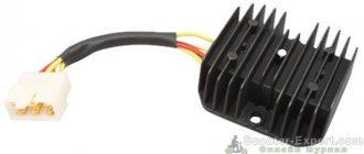
Types of regulator relays
Before you independently repair the voltage regulation device, you must take into account that there are several types of regulators:
- external – increase the maintainability of the generator
- built-in – in the rectifier plate or brush assembly
- regulating by minus - an additional wire appears
- positive regulating – economical connection scheme
- for alternating current generators - there is no function for limiting the voltage on the excitation winding, since it is built into the generator itself
- for DC generators – an additional option for cutting off the battery when the internal combustion engine is not working
- two-level - obsolete, rarely used, adjustment by springs and a small lever
- three-level – supplemented with a special comparison device board and a matching indicator
- multi-level - the circuit has 3 - 5 additional resistors and a tracking system
- transistor - not used in modern cars
- relay – improved feedback
- relay-transistor - universal circuit
- microprocessor - small dimensions, smooth adjustment of the lower/upper threshold of operation
- integral - built into brush holders, therefore they are replaced after the brushes wear out
Attention: Without modification of the circuit, the “plus” and “minus” voltage regulators are not interchangeable devices.
DC generator relay
Thus, the connection diagram for the voltage regulator when operating a DC generator is more complicated. Since in the parking mode of the car, when the internal combustion engine is turned off, it is necessary to disconnect the generator from the battery.
During diagnostics, the relay is checked to perform its three functions:
- Battery cut off when the car is parked
- limiting the maximum current at the generator output
- voltage adjustment for field winding
Any malfunction requires repair.
Alternator relay
Unlike the previous case, diagnosing the alternator regulator yourself is a little simpler. The design of the “automotive power station” already includes the function of cutting off power from the battery while parked. All that remains is to check the voltage at the excitation winding and at the output from the generator.
If the car has an alternating current generator, it is impossible to start it by accelerating down a hill. Since there is no residual magnetization on the exciting winding here by default.
Built-in and external regulators
It is important for a car enthusiast to know that they measure and begin to regulate the relay voltage at a specific location where they are installed. Therefore, built-in modifications act directly on the generator, while external modifications “do not know” about its presence in the machine.
For example, if a remote relay is connected to the ignition coil, its work will be aimed at regulating the voltage only in this section of the on-board network. Therefore, before you learn how to test a remote-type relay, you should make sure that it is connected correctly.
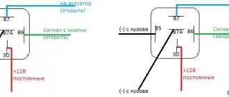
Control by “+” and “–”
In principle, the control circuits for “minus” and “plus” differ only in the connection diagram:
- when installing the relay in the “+” gap, one brush is connected to “ground”, the other to the regulator terminal
- if you connect the relay to the “–” gap, then one brush needs to be connected to the “plus”, the other to the regulator
Operating principle of the regulator relay
Thanks to built-in resistors and special circuits, the relay is able to compare the amount of voltage generated by the generator. After which, too high a value leads to the relay being turned off, so as not to overcharge the battery and damage electrical appliances connected to the on-board network.
Any malfunctions lead to precisely these consequences: the battery becomes faulty or the operating budget increases sharply.
Summer/winter switch
Regardless of the season and air temperature, the operation of the generator is always stable. As soon as its pulley begins to rotate, electric current is generated by default. However, in winter the insides of the battery freeze, and it replenishes the charge much worse than in summer.
The summer/winter switches are either on the body of the voltage regulator, or the corresponding connectors are marked with this designation, which you need to find and connect the wiring to them depending on the season.
There is nothing unusual in this switch, these are just rough settings of the regulator relay, which allows you to increase the voltage at the battery terminals to 15 V.
Connection to the generator's on-board network
If, when replacing a generator, you connect a new device yourself, you need to take into account the following nuances:
- First you should check the integrity and reliability of the contact of the wire from the car body to the generator housing
- then you can connect terminal B of the regulator relay with the “+” of the generator
- Instead of “twists” that begin to heat up after 1–2 years of operation, it is better to use soldering of wires
- the factory wire must be replaced with a cable with a minimum cross-section of 6 mm2 if, instead of a standard generator, an electrical appliance rated for a current of more than 60 A is installed
- The ammeter in the generator/battery circuit shows which power source is currently higher in the on-board network
Ammeters are necessary devices with which you can determine the battery charge and the performance of the generator. It is not recommended to remove them from the scheme without special reasons.
Remote controller connection diagrams
An external generator voltage regulator relay is installed only after determining which wire it should be connected to. For example:
- on old RAFs, Gazelles and Bullheads, relays 13.3702 are used in a polymer or steel case with two contacts and two brushes, mounted in a “–” open circuit, the terminals are always marked, “+” is usually taken from the ignition coil (B-VK terminal) , contact Ш of the regulator is connected to the free terminal of the brush assembly
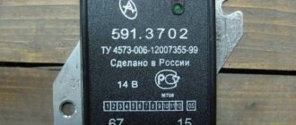
- in “Zhiguli” relay regulators 121.3702 of white and black colors are used, there are double modifications in which, if one device fails, the operation of the second device continues by simply switching to it, mounted in the “+” gap with terminal 15 to the terminal of the ignition coil B-VK, terminal 67 is attached to the brush assembly with a wire
Car enthusiasts call built-in relay regulators “chocolate bars”, labeled Y112. They are mounted in special brush holders, pressed with screws and additionally protected with a cover.
On VAZ cars, relays are usually built into the brush assembly, full marking Y212A11, connected to the ignition switch. If the owner replaces the standard generator on an old domestic VAZ with an AC device from a foreign car or a modern Lada, the connection is made according to a different scheme:
- The car owner decides on the issue of fastening the body independently.
- The analogue of the “plus” terminal here is contact B or B+; it is connected to the on-board network via an ammeter
- Remote relay regulators are usually not used here, but built-in ones are already integrated into the brush assembly, from them comes a single wire marked D or D+, which is connected to the ignition switch (to the coil terminal B-VK)
For diesel internal combustion engines, generators may have a W terminal, which is connected to the tachometer; it is ignored when installed on a car with a gasoline engine.
Checking the connection
After installing a three-level or other relay regulator, a performance check is necessary:
- the engine starts
- The voltage in the on-board network is controlled at different speeds
After installing the alternator and connecting it according to the above diagram, the owner can expect a “surprise”:
- when the internal combustion engine is turned on, the generator starts, the voltage is measured at medium, high and low speeds
- after turning off the ignition with the key... the engine continues to run
In this case, you can turn off the internal combustion engine either by removing the excitation wire, or by releasing the clutch while simultaneously pressing the brake. It's all about the presence of residual magnetization and constant self-excitation of the generator winding. The problem is solved by installing the light bulb's exciting wire into the gap:
- it lights up when the generator is not running
- goes out after it starts
- the current passing through the lamp is insufficient to excite the generator winding
This lamp automatically becomes an indicator that the battery is charging.
Tips and tricks
A common culprit for malfunctioning regulator relays may be oxidation of its terminals. This oxidation results in significant voltage loss. In this case, it is necessary to thoroughly clean the contacts and recheck. The voltage reading at the contacts should be similar to those given by the battery itself, that is, there should be no noticeable losses. Reduced voltage at the contacts indicates that they should be cleaned, and the regulator itself is often in working order. After cleaning, the terminals can be additionally treated with special chemicals that prevent further oxidation.
Finally, I would like to add that the cost of the regulator relay is not high. One of the surest ways would be to replace it with a new element if malfunctions are detected in its operation. Moreover, integrated relay regulators are a part in a monolithic housing that cannot be disassembled for repairs. Savings on this device are not justified, since rapid battery failure or a significant reduction in battery life will entail more serious costs when it is necessary to replace the battery.
Purpose of the voltage regulator relay on the VAZ 2106
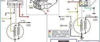
As you know, the power supply system of the VAZ 2106 consists of two important elements: a battery and an alternator. A diode bridge is built into the generator, which motorists in the old fashioned way call a rectifier block. Its job is to convert alternating current into direct current. And to ensure that the voltage of this current is stable, does not depend on the rotation speed of the generator and does not “float” much, a device called a generator voltage relay regulator is used.
This device provides constant voltage throughout the entire on-board network of the VAZ 2106. If there is no relay regulator, the voltage will deviate abruptly from the average value of 12 volts, and it can “float” in a very wide range - from 9 to 32 volts. And since all energy consumers on board the VAZ 2106 are designed to operate under a voltage of 12 volts, without proper regulation of the supply voltage they will simply burn out.
Design of the relay regulator
On the very first VAZ 2106, contact regulators were installed. It is almost impossible to see such a device today, since it is hopelessly outdated, and it has been replaced by an electronic regulator. But to get acquainted with this device, we will have to consider the contact external regulator, since its example reveals the design most fully.
So, the main element of such a regulator is a winding of brass wire (about 1200 turns) with a copper core inside. The resistance of this winding is constant and is 16 Ohms. In addition, the regulator design includes a system of tungsten contacts, an adjustment plate and a magnetic shunt. There is also a system of resistors, the connection method of which can change depending on the required voltage. The highest resistance these resistors can provide is 75 ohms. This entire system is housed in a rectangular PCB body with contact pads for connecting wiring brought out.
Operating principle of the relay regulator
When the driver starts the VAZ 2106 engine, not only the crankshaft in the engine begins to rotate, but also the rotor in the generator. If the rotation speed of the rotor and crankshaft does not exceed 2 thousand revolutions per minute, then the voltage at the generator outputs does not exceed 13 volts. The regulator does not turn on at this voltage, and the current goes directly to the excitation winding. But if the speed of rotation of the crankshaft and rotor increases, the regulator automatically turns on.
The winding, which is connected to the generator brushes, instantly reacts to an increase in crankshaft speed and is magnetized. The core located in it is pulled inward, after which the contacts on some internal resistors are opened, and the contacts are closed on others. For example, when the engine is running at low speeds, only one resistor is used in the regulator. When the engine reaches maximum speed, three resistors are turned on, and the voltage on the excitation winding drops sharply.
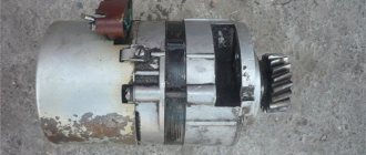
Application of generators.
Reasons for VAZ 2110 battery discharge
The VAZ 2107 charging scheme depends on the type of generator used in the car. To recharge the battery on VAZ-2107 (2104, 2105) cars with a carburetor engine, a G-222 type generator or similar with a maximum output current of 55A is used. On VAZ-2107 cars with an injection engine, a generator of type 5142.3771 or similar, the so-called high-energy generators, with a maximum output current of 80 - 90A is used, depending on the design. It is possible to install more powerful generators with an output current of up to 100A. All types of alternating current generators with a built-in rectifier unit (diode bridge) and a voltage regulator, made in one housing with brushes or a removable one mounted on the housing.
Signs of a broken voltage regulator
When the voltage regulator fails, it no longer keeps the voltage supplied to the battery within the required range. As a result, the following problems occur:
- The battery is not fully charged. Moreover, the picture is observed even when the battery is completely new. This indicates a break in the relay regulator;
- the battery is boiling. This is another problem indicating a breakdown of the relay regulator. When a breakdown occurs, the current supplied to the battery can be several times higher than the normal value. This leads to the battery overcharging and boiling.
In both the first and second cases, the car owner must check the regulator and, if a breakdown is detected, replace it.