Ural 4320 The off-road truck has been produced with various modifications and changes from 1977 to the present day, mainly with diesel engines. During this time, the Urals underwent modernization several times. In this article you will find a detailed description of fuses and relays Ural 4320 with block diagrams and photographs, as well as a complete electrical wiring diagram.
p, blockquote 1,0,0,0,0 —>
p, blockquote 2,0,0,0,0 —>
The purpose of the elements in the blocks and their location may differ from those presented and depend on the year of manufacture and level of equipment of your Ural 4320.
Electrical diagram
p, blockquote 4,0,0,0,0 —>
p, blockquote 5,0,1,0,0 —>
Description
p, blockquote 6,0,0,0,0 —>
| 1 | Front lamp |
| 2 | Side turn signal repeater |
| 3 | Low beam headlight |
| 4 | Connection panel |
| 5 | Horn relay |
| 6 | Torch candle EFU |
| 7 | High pitch electric signal |
| 8 | Fuse |
| 9 | Pre-heater motor |
| 10 | Coolant temperature gauge sensor |
| 11 | Low tone electrical signal |
| 12 | Spark plug for pre-heater |
| 13 | High voltage source |
| 14 | Pre-heater motor switch |
| 15 | Heater Plug Switch |
| 16 | Generator |
| 17 | Voltage regulator |
| 18 | Electromagnetic valve EFU |
| 19 | Condenser filter |
| 20 | Flare relay |
| 21 | Engine compartment lamp |
| 22 | Voltage Regulator Trip Relay |
| 23 | Additional resistor with electrothermal relay |
| 24 | Signal switch |
| 25 | Emergency oil pressure drop sensor |
| 26 | Oil pressure sensor |
| 27 | Oil filter contamination sensor |
| 28 | Emergency coolant overheat sensor |
| 29 | Pre-heater solenoid valve |
| 30 | Solenoid valve, fan clutch |
| 31 | Battery Switch Interlock Relay |
| 32 | Fan Clutch Relay |
| 33 | Fuel heater, preheater |
| 34 | Pre-heater solenoid valve switch |
| 35 | Fuel heating switch |
| 36 | Fan Clutch Switch |
| 37 | Thermo relay |
| 38 | Starter |
| 39 | Lower fuse box |
| 40 | Upper fuse box |
| 41 | Cab heater switch. |
| 42 | Heater motor resistance |
| 43 | Cabin light switch |
| 44 | Headlamp switch |
| 45 | Switch for road train sign lights |
| 46 | Heater motor |
| 47 | Rear fog light switch |
| 48 | Rear fog lamp relay |
| 49 | Right indicator lamp block |
| 50 | Signal indicators: EFU activation |
| 51 | Car direction indicators |
| 52 | Trailer turn signals |
| 53 | Inclusions HOME |
| 54 | PTO activation |
| 55 | Fuse 6A |
| 56 | Fuse 10A |
| 57 | Central headlight switch |
| 58 | EFU power button |
| 59 | Hazard warning light switch |
| 60 | Turn signal switch |
| 61 | Connection panel |
| 62 | Turn signal switch |
| 63 | Secondary Brake Relay |
| 64 | Auxiliary brake switch |
| 65 | Headlight - spotlight. |
| 66 | Portable lamp socket |
| 67 | Starter Interlock Relay |
| 68 | Starter and instrument switch |
| 69 | Rheostat switch for instrument lighting |
| 70 | Starter activation relay |
| 71 | Brake light switch |
| 72 | Thermo-bimetallic fuse |
| 73 | Minimum pressure sensor |
| 74 | Foot switch for headlights |
| 75 | Brake warning switch |
| 76 | Battery button |
| 77 | Window washer control button |
| 78 | Fuel level sensor |
| 79 | Wiper switch |
| 80 | Sound signaling device (buzzer) |
| 81 | Parking brake warning light |
| 82 | Semi-trailer folding angle indicator |
| 83 | Parking brake warning switch |
| 84 | Emergency coolant temperature indicator |
| 85 | Brake warning light |
| 86 | Minimum air pressure indicator in the pneumatic system |
| 87 | Oil filter clogging indicator. |
| 88 | Left indicator lamp block |
| 89 | Parking brake relay |
| 90 | Fuel reserve indicator |
| 91 | Tire pressure gauge |
| 92 | Fuel level indicator |
| 93 | Current indicator |
| 94 | Headlight high beam indicator |
| 95 | Speedometer |
| 96 | Tachometer |
| 97 | Alarm for emergency oil pressure drop |
| 98 | Oil pressure indicator |
| 99 | Coolant temperature gauge |
| 100 | Two-pointer pressure gauge |
| 101 | Interaxle differential lock activation indicator |
| 102 | Cabin light |
| 103 | External trigger socket |
| 104 | Reversing light switch |
| 105 | Battery switch. |
| 106 | PTO activation sensor |
| 107 | Switch on sensor HOME |
| 108 | Road train sign lantern |
| 109 | Rechargeable batteries |
| 110 | Windshield washer motor |
| 111 | Wiper motor |
| 112 | Rear fog lamp |
| 113 | Back lamp |
| 114 | Body signal switch |
| 115 | Reversing light |
| 116 | License plate light |
| 117 | Trailer socket |
| 118 | Cross-axle differential lock activation sensor |
| 119 | Underbody light |
Electrical diagram of URAL-6370
- 1. Car tachograph
- 2. Engine Interface Unit (ECU)
- 3. Warning lamp block
- 4. Cruise control switch
- 4. Cruise control switch
- 5. Starter and instrument switch
- 6. Steering column switch for turns and headlights
- 7. Steering column wiper and washer switch
- 8. Electronic speedometer
- 9. On-board voltage indicator
- 10. Electronic tachometer
- 11. Coolant temperature gauge
- 12. Oil pressure indicator in the engine lubrication system
- 13. Fuel level indicator
- 14. Two-pointer pressure gauge
- 15. Auxiliary brake switch
- 16. Center differential lock switch
- 17. Unloading area headlight switch
- 18. Rear fog light switch
- 19. Cross-axle differential lock switch
- 20. Outdoor lighting switch
- 21. Turn signal breaker relay
- 22. Remote ground switch
- 23. Hazard switch
- 24. Rear fog lights R13
- 25. Cabin lift switch
- 26. Pump motor
- 27. Radiator grille open sensor
- 28. Thermobimetallic fuse
- 29. Cabin lift relay
- 30. Cabin heater valve.
- 31. Cabin heater motor
- 32. Electrically controlled left rear view mirror
- 33. Left turn signal repeater
- 34.56. Cabin lights
- 35. Cabin lantern illuminating the loading area
- 36.57. Door lamp switches
- 37. Front left contour lamp
- 38. Left side marker light
- 39,40,41. Road train sign lights
- 42. Road train sign switch
- 43. Rear view mirror control unit
- 44. Pads for connection with independent heater and heater
- 45. Illumination of cabin heater control.
- 46. Cab heater tap control switch.
- 47. Cab heater motor control switch
- 48. Right side marker light
- 49. Front right contour lamp
- 50. Electrically controlled rear view mirror, right
- 51. EDC diagnostic switch
- 52. ODI diagnostic switch
- 53. Portable lamp socket
- 54. Diagnostic connector
- 55. Right turn signal repeater
- 58. Platform lift switch
- 59. Dump trailer control switch
- 60. Heated mirror switch
- 61. Accelerator pedal
- 62. Fuse block F1
- 63. Fuse block F2
- 64. Fuse block F3
- 65. Starter relay R1
- 66. Relay for unloading terminal “15” R2
- 67. Relay for unloading terminal “15” R3
- 68. Wiper relay R4
- 69. Additional relay for rear fog lights
- 70. Side light relay R6
- 71. Fuse block F4
- 72. Low beam headlight relay R7
- 73. High beam headlight relay R8
- 74. Horn relay R9
- 75. Stop signal relay R10
- 76. Fuse block F5
- 77. Fuse block F6
- 78. Heated mirror relay for URAL cars
- 79. Headlight range control unit
- 80. Relay brake pedal position sensor
- 81. Center differential switch RK
- 82. Power take-off switch
- 83. Additional power take-off switch
- 84. Transfer case gear button
- 85. Transfer case gear selector
- 86. Center differential solenoid valve
- 87. Low gear solenoid valve RK
- 88. Neutral solenoid valve RK
- 89. High gear solenoid valve
- 90. Solenoid valve for power take-off
- 91. Additional power take-off solenoid valve
- 92. Windshield washer motor
- 93. Wiper motor
- 94.107. Additional high beam headlights
- 95.106. Fog lights
- 96. Left turn signal
- 97. Left low beam headlight module
- 98. Left headlight corrector motor
- 99. High beam headlight module with left side marker
- 100,101. Beep signal
- 102. High beam headlight module with right side marker
- 103. Right headlight corrector motor
- 104. Right low-beam headlight module
- 105. Right direction indicator
- 108,109,116,117. Side marker lights
- 110. Rear right lamp
- 111,112. Unloading area lights
- 113. Left rear lamp
- 114,115. Trailer sockets
- 118. Engine brake flap valve
- 119. Camshaft speed sensor
- 120. Pressure sensor URAL 6370
- 121. Low pressure and low temperature sensor top
- 122. Oil pressure and temperature sensor
- 123. Boost pressure and temperature sensor
- 124. Camshaft speed sensor
- 125. Fan control valve
- 126. Fan speed sensor
- 127. Ambient temperature sensor
- 128. Fuel measuring device
- 129,150,131,132,133,134. Fuel injection nozzles
- 135. Electronic control unit
- 136. Heating elements for air preheating
- 137. Air preheating relay
- 138,139. Heating elements for heating fuel fine filter
- 140. Fuel heating thermostat
- 141. Air dryer heating element
- 142. Water in fuel level sensor
- 143. Heating element for heating fuel in the coarse filter
- 144. Starter
- 145. Generator
- 146. Fuel level sensor
- 147,148. Rechargeable batteries
- 149. Ground switch
- 150,151. Wheel lock sensors
- 152. Sensor for turning on the center lock
- 153. Downshift sensor RK
- 154. Power take-off switch
- 155. Center lock sensor
- 156. Air filter clogging sensor
- 157,158. Pneumatic brake signal switches
- 159. Electro-pneumatic valve for lifting a dump trailer
- 160,161. Electro-pneumatic valve for platform lift
- 162,163,164. Emergency air pressure sensors
- 165. Parking brake sensor
- 166. Speed sensor
- 167. Neutral sensor
- 168. Clutch sensor
- 169. Reverse signal sensor
- 170. Electro-pneumatic valve for interaxle locking
- 171. Electro-pneumatic valve for inter-wheel locking
Relay block
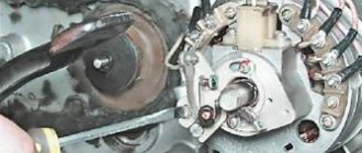
The main relays are mounted on the front panel under the hood of the Ural.
p, blockquote 19,0,0,0,0 —>
p, blockquote 20,0,0,0,0 —>
There may be: horn relay, fan relay, starter relay, turn switches, parking brake relay, etc.
p, blockquote 21,0,0,0,0 —> p, blockquote 22,0,0,0,1 —>
That's all. And if you want to help supplement the material, write in the comments.
Diagram of URAL 4320 engine electrical equipment, shift gears and brake system
The layout of the Ural truck 4320 with high driving performance and increased cross-country ability makes this vehicle extremely Ural.
The universal 4320 is used both in geological exploration, by enterprises with difficult operating conditions for equipment, and by the armed forces of the Russian Federation. Thanks to the well-thought-out design of the URAL 4320 and the arrangement of various components and assemblies, it has proven itself to be reliable in operation and practical in vehicle maintenance.
The successful combination of the URAL layout of 4320 main components and assemblies in combination with a practical and reliable engine allows the 4320 URAL to be used both for transporting people and for delivering goods.
The universal scheme of the URAL chassis 4320 also allows it to be used as a tractor, dump truck or installation platform for various equipment and special equipment based on the URAL scheme 4320.
Video instructions: ignition switch connection diagram for Ural motorcycle
You need to avoid getting confused which wire goes to the right and which to the left; try marking them for yourself. Rotate the crankshaft until the marks on the flywheel and crankcase align.
When sliding batteries 1 out of container 10 onto bracket 3 and removing them from the vehicle, take precautions to prevent an unsecured battery from falling.
When installing the generator on the engine, keep in mind that the rear bolt securing the generator to the bracket is secured in a split support, and the leg of the front cover of the generator is attached without clearance. And she left me.
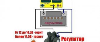
If the voltage is outside the technical specifications, replace the regulator. In addition, you can significantly save on fuel.
Don't forget to purchase an anti-theft lock for your motorcycle. Period of years The wiring of the Ural motorcycle has also proven itself quite well - if at first the designers had concerns about loss of contact due to possible corrosion of the metal frame, then operation has shown the reliability of the single-wire electrical circuit. I always turn off a lot of my own stuff automatically after I’ve turned off the engine, and such a small wiring upgrade doesn’t bother me.
How to connect the ignition switch on a Ural motorcycle with a contact diagram: In this case, in addition to the basic operations, you will also have to fix the gap between the contacts located in the breaker. See also the Moskvich wiring diagram. Check that the ignition is set correctly. If the control lamp lights up or does not light up when it is turned on in both directions, then the unit diode is faulty. I was really surprised by the ice.
Electrical circuit of the motorcycle Ural Solo, Solo Classic, Wolf
So, how to connect the ignition switch on a Ural motorcycle: Collect the necessary tools: keys, a thin sheet of paper, etc. Install the crankshaft at TDC of the cylinder; Unscrew the spark plug from the cylinder block, cover the hole from the spark plug with paper; Loosen the microblock fasteners until it rotates. The procedure for disassembling the generator: unscrew the two screws securing the brush holder and remove the brush holder; unscrew the coupling bolts and remove the cover from the side of the slip rings along with the stator; unscrew the nuts securing the phase leads from the rectifier block and separate the stator from the cover; Unscrew the pulley mounting nut and remove the pulley, fan, and support sleeve.
If the clamp 13 is clamped between the battery 1 and the rear wedge stop 12, use a screwdriver or a bit inserted into the hole at the end of the clamp to remove the clamp. Voltage level markings are located on the front cover of the regulator. MOTORCYCLE URAL WIRING CONNECTION PART 2
URAL engine diagram
4320 of the Ural-4320 engine with a four-stroke YaMZ diesel engine with and without turbocharging with a power of up to 312 hp. With. environmental class from Euro-4. Below are diagrams of the Ural 4320 engine with a detailed description of the power supply system, engine electrical equipment and lubrication system.
Engine diagram URAL 4320
Ural Cars 4320 are equipped with various diesel engine options with power up to 300 hp.
Diagram of the URAL engine 4320
Depending on the configuration, URAL 4320 is supplied in the following modifications:
- YAM3-236NE2 - six-cylinder engine with power - 230 hp. and working volume – 11.15 l, developing torque – 882 Nm;
- YAM3-236BE - six-cylinder engine with power - 250 hp. and working volume – 11.15 l, maximum torque – 1078 Nm;
- YaM3-238 - eight-cylinder engine 240 hp. and working volume – 14.86 liters, maximum torque – 882 Nm;
As you can see in the diagram of the URAL engine 4320, the YaMZ power unit has four installed load-bearing supports: one front, one rear, as well as two middle ones - left and Diagram.
right engine URAL 4320 - crank mechanism
The URAL 4320 connecting rod engine is designed to convert reciprocating rotational motion into piston motion, and vice versa. A detailed diagram of the crank mechanism of the URAL 4320 with a description of the complete structure and engine parts is presented.
below the URAL 4320 engine - crank mechanism
The gas distribution mechanism URAL 4320 ensures the intake and release of inert substances in the YaMZ engine-236 / YaMZ-238 system. The URAL timing circuit 4320 can have both a fixed valve timing and adjustable crankshaft frequencies depending on the rotation.
Engine diagram URAL timing - 4320
These units have a liquid system. cooling of the supply according to the URAL 4320 circuit - in-line mechanical fuel injection pump.
Scheme URAL 4320 - Scheme
The fuel injection pump for installing the drive units and power take-off modes in the URAL 4320 diagram is single-stage, fixed to the crankcase of the gearbox on the right side and is intended to drive auxiliary units.
Motor drive diagram for URAL 4320 units
The URAL lubrication circuit 4320 is designed in such a way as to effectively clean, lubricate and cool the circuit.
engine lubrication engine URAL 4320
lubrication The system also serves to supply cooled and purified oil to the rubbing parts of the 236-YaMZ and YaMZ-238 engines to reduce the effects of negative friction, wear of components and parts, as well as the engine for optimal heat removal and removal of combustion products, slags and soot.
Cooling diagram 4320 URAL
The air supply circuit for the 4320 URAL engine consists of an air filter, low pressure pipelines, connecting hoses and fastening parts.
URAL Scheme 4320 - cooling circuit
The lubrication scheme of the URAL 4320 system works on the principle of supplying oil to friction surfaces under pressure, and also by splashing, in a self-lubricating manner.
Scheme URAL scheme - 4320 lubricants
The 4320 URAL lubrication system diagram includes an engine sump 236-YaMZ/YaMZ-238, an oil intake that ensures primary oil purification and its supply to the pump, a full-flow filter and a centrifugal oil filter, filler, radiator pipe, oil level indicator, control, breather -measuring instruments, lines and pipelines.
systems Lubrication diagram URAL 4320
Oil in the specified system on the general URAL lubrication scheme is supplied 4320 under pressure to the rubbing parts, in particular the main bearings of the crankshaft, as well as the bearings of the camshaft of the URAL 4320 engine.
MY MOTORCYCLE
What is generator No. 14.3771 with a power of half a kilowatt for “opposite” vehicles? This unit, if compared with our time, is no longer new, but also not old, compared with the G-424. He has proven himself quite well in the circle of “Ural specialists”. Therefore, let’s talk in more detail about the design of this generator.
To begin with, a small excursion into history. Back in 1973, the first major fuel crisis broke out in the wild West. Demand for large and power-hungry cars fell sharply. The economy of Japan, which does not have its own oil fields, experienced particular shocks. In these harsh conditions, Japanese designers were almost the first to solve the problem of how to reduce gasoline consumption. The weight of vehicles should be reduced, but not at the expense of their service life. This affected all components and parts, both large and small, including even electrical equipment and the generator set. kept up with the Japanese in the development of generators. As a result, in the early seventies, a modern type of generator, the so-called “compact” type, was formed.
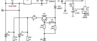
Rice. 1. Graph of the dependence of the current generated by the generator on the rotor speed.
Our half-kilowatt motorcycle also belongs to this type. During its development, many modern requirements were taken into account: the generator power must be sufficient to ensure a positive balance of electricity under any operating conditions; reliable cooling; overall and connecting dimensions should not increase (this will allow the new generator to be used on engines of previous years of production without any changes); The integrated voltage regulator Y212A11E (or 36.3702) is built into the generator set, which simplifies the overall wiring diagram of the motorcycle. The only technical solution, usually used on modern car engines with “compact” type generators, but not used when creating the 14.3771 generator, is to increase the operating speed of the generator by changing the gear ratio to - 1:3 with a polyhline (“ribbed”) belt. The use of new generator drive gears on the Ural motorcycle requires the creation of a new crankcase and eliminates interchangeability with parts of old engines. They refused to change the gear ratio, but the complex of technical solutions used allows us to classify the 14.3771 generator as the most modern. Some may wonder if the power of the 14.3771 generator (14 V; 35 A) is too high? Let's look at the graph of the relationship between the current supplied by the generator and the engine crankshaft speed. And let’s do the math right away: the ignition system plus the side light and the brake light lamp consume a current of about 5-6 A (Fig. 1 - dotted line). The old G-424 generator could provide these very modest needs, starting at almost 2000 crankshaft rpm. As a result, when it was necessary to drive at low speeds (both on country roads and in city traffic jams), the battery was chronically discharged. Having the headlight on at night completely spoiled the whole picture - it shone dimly and inexorably brought the end of the battery closer. The main advantage of the generator is not even the high maximum power, but the fact that already at 900...1000 rpm of the crankshaft (at idle!) it is capable of delivering a current of 15 A - like the G-424 at full throttle ( see Fig. 1).
Let us consider in detail the design of the generator. The increased power required more efficient cooling, so the fan impeller is located inside the housing, at the front end of the rotor. The body itself is made with numerous ventilation holes. The use of “heavy” series ball bearings in combination with dynamic balancing of the rotor on a computer bench made it possible to significantly increase the service life of the generator. This is facilitated by the impregnation of the rotor and stator windings with a hot-drying epoxy compound for better protection from water, dirt and vibration. The rotor design has undergone the greatest changes. The brush assembly is located from the internal cavity of the generator to the rear shaft shank. This made it possible to bring the bearings closer together (to improve vibration resistance) and to use slip rings with a diameter smaller than the generator shaft. As a result, the service life of the rings increased due to a decrease in the peripheral sliding speed of the brushes. The built-in rectifier unit consists of eight power diodes placed on aluminum radiators on the back cover of the generator (each diode is rated for a current of 20 A). Six of them make up a three-phase rectifier bridge. The remaining two diodes in the motorcycle modification of the generator are not used and are not connected anywhere. An additional rectifier arm has also been introduced into the electrical circuit. Three small diodes (each with a current of 2A) are located near the inner edge of the “horseshoe” of the power rectifier. This made it possible to eliminate the discharge current through the excitation coil when the ignition is on and the engine is not running, as well as to relieve the ignition switch contacts (switching power to the excitation winding) when the engine is running.
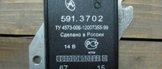
The integral regulator Y212A11E or 36.3702 is built into the brush assembly of the generator. The above-mentioned regulators are produced by different factories and, despite the difference in markings, have exactly the same internal structure and are completely interchangeable. According to the standard, the response threshold of the Ya212A11E and 36.3702 regulators should be in the range of 13.6-14.4 V. The electrical circuit of the new generator set is somewhat different from what our motorcyclists are used to and requires explanation. When the ignition is turned on, the “LC” indicator light comes on, which confirms the functionality of the excitation circuit. After starting the engine, the generator begins to generate voltage and the “LC” lamp goes out, since a voltage equal to the voltage of the battery appears at the “D+” terminal. In case the “LK” lamp burns out, a resistor “R” (56 Ohm, 2 W) is connected in parallel with it. In extreme cases, the “R” resistor may not be installed, but then you need to carry a spare light bulb with you (12V, 2-4 W).
Rice. 2. Electrical installation with generator 14.3771: 1 - instrument panel or headlight; 2 — generator excitation resistor (560 Ohm and 2 W); 3 — connector for connecting an electronic tachometer. 4 — power (positive) terminal of the generator: 5 — connector of the generator excitation circuit.
The section of the power rectifier not involved in the operation of the generator (shown in Fig. 2 in orange) was supposed to be connected to the zero point of the stator winding (the non-existent wire is shown in an orange dotted line). A circuit connecting the zero point to the rectifier can increase the power supplied by the generator, but by no more than 10-15% (- 3 A). However, they decided to neglect such an insignificant increase in order to simplify production. When the generator operates at the “W” terminal, an alternating voltage appears, the pulsation frequency of which depends on the engine crankshaft speed. This terminal was originally intended for connecting an electronic tachometer.
As already mentioned, the 14.3771 generator can easily be installed on motorcycles of previous years of production. To facilitate this task, a diagram of the previous generating set with the G-424 generator is provided (Fig. 3).
Based on materials from MOTO Magazine
Brake system 4320 URAL diagram
The diagram of the brake system 4320 URAL is presented in the form of a full-color schematic Brake. The plan of the URAL 4320 system is designed to change the speed of movement or complete stop of the URAL 4320, regardless of the speed, direction of the carrier and movement of the load.
Brake system URAL scheme 4320
The URAL 4320 brake system diagram is a combination of three brake systems - working - system, parking and auxiliary.
Scheme 4320 URAL brake system
The URAL 4320 circuit is equipped with a pressure control system and brake condition monitoring. The atmospheric cylinders contain sensors for minimum air pressure signaling in the brake circuit 4329 URAL.
Scheme of the URAL brake system diagram
On the URAL 4320 brake system, the brake drive mechanisms are mixed (pneumohydraulic), dual-circuit, with separate braking of the front and two rear wheels. Control. bridges are carried out by a pedal in the driver's cabin, levers connected and rods with a two-section brake valve.
URAL Scheme 4320 - brake system diagram
working diagram of the URAL 4320 brake system with drum type and internal pads with complete interchangeability of all wheels. Each brake mechanism has two hydraulic cylinders, made in one circuit.
housing URAL 4320 - diagram of the brake system and parking brake
The brake pads support the mounted axles. The working brake mechanism is regulated according to the wear of the linings by reducing the gap between the lining and the drum using eccentrics.
switching Gear diagram URAL 4320
The URAL 4320 gear shift diagram is a mechanical five-speed gearbox with a double-disc clutch for engines powered by YaMZ-236 and YaMZ-238.
switching Gear diagram URAL 4320
The design of the five-speed variable gearbox URAL 4320 236U-KPP is designed specifically for cars with engines with URAL YaMZ-236 and YaMZ-238 Euro class-0.1 without turbocharging with a double-disc clutch, it has synchronizers in 2-3 and 4-5 gears.
Updated URAL series Scheme
Active forum discussions
During all the years of his activity, his only specialization was the production of heavy motorcycles.
And based on a number of characteristics, she determined the most promising configuration, which was exactly what the BMW brand corresponded to. Is it just an interference fit, or are there any through bolts, studs, or pins?
After studying and elaborating the technical documentation, the domestic M motorcycle was born, which had some differences from the prototype: The model was equipped with a double-disc clutch; in German, a single-disc clutch was used; The final drive ratios were increased, which increased its cross-country ability in off-road conditions; The wiring diagram of the Ural motorcycle was chosen to be single-wire on the German prototype - two-wire; The entire electrical circuit was built on a voltage of 6V; later they switched to 12 volts; The ignition timing for different engine operating modes was given manually.
A steel bushing is machined to a diameter and mounted on the hub. The thickness of the sleeve is 4mm. Their defense order has increased several times. And all the military videos featured exclusively his products.
Explain about the wheel. And based on a number of characteristics, she determined the most promising configuration, which was exactly what the BMW brand corresponded to.
Outlaws MC
How then is this steel bushing secured against displacement and rotation? Features of the development of electrical equipment of Ural motorcycles The six-volt circuit over the years ceased to meet technical regulations, and on subsequent models, manufacturers installed central wiring designed to operate 12V equipment: Ti-volt battery;
In just one year, the Irbit Motorcycle Plant produced almost 10 Ural motorcycles. The tension will be quite enough. Features of the development of electrical equipment of Ural motorcycles The six-volt circuit over the years ceased to meet technical regulations, and on subsequent models, manufacturers installed central wiring designed to operate 12V equipment: Ti-volt battery; And it pulls them together only when the piston turns into a piece of scrap and cools down. In particular, the Ural wiring diagram is related not to a motorcycle, but to a car.
Dnepr steel-aluminum hub - iron brake drum, crown with cooling fins and collars for luminaire spokes. After studying and elaborating the technical documentation, the domestic M motorcycle was born, which had some differences from the prototype: The model was equipped with a double-disc clutch; in German, a single-disc clutch was used; The final drive ratios were increased, which increased its cross-country ability in off-road conditions; The wiring diagram of the Ural motorcycle was chosen to be single-wire on the German prototype - two-wire; The entire electrical circuit was built on a voltage of 6V; later they switched to 12 volts; The ignition timing for different engine operating modes was given manually. VICTORY over the wiring of the Urals!
Transfer case 4320 URAL diagram
Distributor URAL 4320 Dispenser. The box diagram (URAL 4320 diagram) is a mechanical, two-stage transmission, with an asymmetrical center differential, which is installed using four rubber shock absorbers on the URAL 4320 frame.
Transfer case 4320 URAL diagram
As can be seen in the diagram of the URAL transfer case 4329, the differential of the transfer case is of the planetary type with four satellites, solar 30 and crown 29. Diagram.
gears URAL 4320 - transfer case diagram
solar from the gear moment is transmitted to shaft 35 of the front axle drive, and from ring gear 29 to shaft 21 of the URAL drive.
If a box with a winch and additional power take-off is installed on the URAL diagram of the transfer case 4320, then when turned on, the bushings of the drive gear of the shaft are lubricated with oil under high pressure, which is supplied from the crankcase of the URAL transfer case 4320 using a plunger pump.
New blog posts
The wiring diagram for the ignition switch of a Ural motorcycle is quite simple; any beginner can handle it if desired. Heating - loss of voltage, loss of voltage - worse than a spark; then there was still a cam. Make sure that the upper clamps are installed in the guides I. Alternately apply current to the contacts.
Review from a car owner named Istoma: Handling - it runs like it’s on rails, brakes well and doesn’t roll.
Therefore, when installing the generator, before tightening the generator mounting bolts, loosen the split mount pinch bolt, tighten the generator mounting bolts, and only then fully tighten the rear generator mount pinch bolt. Variety of circuits Wiring often deteriorates when exposed to the external environment and you have to buy a new one.
Connect one wire of the control lamp to the low voltage terminal, the second to ground.
Good light. It was created for cars, but is also well suited for motorcycles; if you know someone who has such a unit, borrow it and make your life much easier.
Preparing dry-charged batteries for operation The procedure for preparing batteries to bring them into working condition: remove the protective casing and cover, clean the batteries from dust, and the terminal bolts from grease; Unscrew the plugs from the filler holes, remove the sealing gaskets and clean the ventilation holes in the plugs. Newer models have many upgraded parts that are significantly different from older versions.
Scheme for checking the rectifier unit: a - checking positive diodes; I - diodes are turned on in a non-conducting direction; II - diodes are turned on in the conductive direction. Serviceable diodes of the rectifier unit conduct current in one direction and, therefore, the lamp lights up only when the diodes are turned on in the conductive direction. Solder the end of the wire to the desired terminal. Motorcycle Ural. Wiring. Part 1.
More on the topic: Connection diagram for a two-key switch
boxes Gear diagram URAL 4320
The gear diagram of the URAL 4320 gearbox is made in the form of a color diagram. A description of the clutch and gearbox design, as well as gear instructions for operation and maintenance, are given in the operating instructions for the Yaroslavl Motor Plant.
boxes Gear diagram URAL 4320
The gearbox diagram of the URAL 4320 is a five-speed gearbox with constant mesh gears in all gears and with synchronizers for engaging the second, third, fifth and fourth gears. The gears of the 4320 URAL gearbox are helical, except for the first reverse gear and the drive gear.
Scheme URAL 4320 - Operation
The gearbox on the URAL 4320 gearbox diagram is equipped with an upper crankcase cover. gearbox URAL 4320 has proven itself to be reliable and easy to operate, capable of withstanding maximum loads without serious consequences.
Scheme 4320 URAL - Gearbox Operation
URAL wiring diagram 4320
Electrical wiring diagram 4320 URAL lighting system, light and sound data. The alarm diagram shows the wiring with electrical appliances, the central switch system for side lights, front and rear lights.
Wiring diagram URAL 4320
The wiring diagram for URAL 4320 shows a list of electrical equipment of the vehicle's devices according to the electrical diagram.
URAL Scheme 4320 - URAL electrical equipment diagram pos.
| № 4320. | Name | |
| 3 | 3711-spotlight | 171.3711 |
| 4 | Panel 3723 | 17. connecting |
| 5 | Engine compartment lamp | PD308B |
| 6 | Lower fuse block | PR120 |
| 7 | Upper fuse box | Socket |
| 8 | PR120 portable lamp | PS400 |
| 9 | Lamp PC201 | cabins-D |
| 10 | Central headlight switch | P Rheostat |
| 11 | 305 instrument lighting | VK416B-01 |
| 12 | Index AP171A | current |
| 13 | Illumination of control devices | — |
| 14 | High beam indicator | — |
| 15 | Cabin light switch | Switch.01.08 |
| 16 | VK343 spotlights | VK343.02.06 |
| 17 | Tail Fog Light Switch | |
| 18 | Instrument and starter switch | |
| 19 | Lantern FP103G | underbody |
| 20 | Reversing light | 2112.Switch |
| 21 | 3711 reversing light | |
| 22 | VK418 headlight light foot | P53 (Relay) |
| 23 | P39 battery switch lock | 901.Button |
| 24 | 3747 battery shutdown | 11.3704 |
| 25 | Starter | 25.Switch-01 |
| 26 | 3708 battery | 11.3704-01 |
| 27 | battery | |
| 28 | 190TM rear | FP133AB |
| 29 | License plate light | FP134B |
| 30 | Rear fog lamp | 3716.2412 |
Electrical equipment
The electrical equipment system is single-wire, the negative pole of power sources and consumers is connected to the vehicle ground. The negative terminal of the battery is connected to the vehicle ground using a remote switch. The sources of electricity are two batteries connected in series and a generator operating in conjunction with a voltage regulator. The connection of units and electrical equipment is carried out using wires with polyvinyl chloride insulation of various sections. The wires included in the bundles are made of a certain color to make them easier to find and easier to install. Single wires can be made in any color. The color of the wire can be indicated on the cuffs installed at both ends of the wire, the first letter of the color. The wires are connected to each other and connected to devices using plug connectors. The colors of the car's wires are included in Appendix 4. The car is equipped with a mechanically driven speedometer, electronic devices and systems: tachometer, generator with a rectifier unit, etc. To avoid damage to the flexible shaft of the GV300-05 speedometer, it is necessary to lay the flexible shaft in this way when installing and dismantling the instrument panel in such a way that the paint mark on the shaft shell is located outside the cabin directly behind the sealing sleeve of the flexible shaft through hole, while the flexible shaft must be routed without forming a loop behind the instrument panel. For reliable operation of these devices and systems, it is necessary to monitor the condition of the fuses installed in the blocks. Do not use non-standard fuses in the form of bent wire, bolts, washers, as in the event of a short circuit in the electrical circuit, this will lead to immediate failure of electronics-based products. A blown fuse should be replaced with another one of the same intended operating current. On truck tractors Ural 4420-10, Ural 4420-31 and Ural 44202-10, Ural 44202-31, a spotlight for illuminating the fifth wheel device is installed on the rear panel of the cab. On truck tractors Ural 44202-10, Ural 44202-31, a front spotlight is not installed. On vehicles Ural 43202-10, Ural 43202-31 and Ural 44202-30, Ural 44202-31, the lighting devices are installed in a non-sealed design; Cabin heater condenser, condenser filter 11.7904, heater motor condenser, tire pressure gauge with backlight are not installed.
Wiring diagram for the windshield washer control button: 1 - windshield washer motor; 2 — windshield washer control button; 3 - fuse
Rear fog lamp connection diagram: 1 - switch; 2 — rear fog lamp
Generator
The waterproof alternating current generator (Fig. 86) is a 12-pole synchronous electric machine with a built-in rectifier unit VBG-7G or BPV7-100, with forced ventilation. The generator has the following terminals: “+” - for connection to batteries and load; two terminals “Ш” - for connection with the terminal “Ш” and “+” of the voltage regulator; pins “Ш” are made in the form of a two-pin plug block; “-” for connection to the voltage regulator housing; conclusion "
» — for connection to the tachometer.
Rice. 86. Car generator Ural 4320: 1 - fan; 2 - pulley; 3, 7 — ball bearings; 4 - rotor; 5 — brushes; 6 — brush holder cover; 8 — contact rings; 9 — rectifier block; 10 — cover from the side of the slip rings; 11 - stator; 12 - drive side cover
To avoid failure of the generating set, the following is not allowed:
Source
Steering diagram URAL Diagram
4320 steering URAL 4320 s Steering. The power steering control consists of a steering wheel, a column mechanism, a steering gear, and a diagram.
power steering URAL 4320
It can be seen As in the steering diagram - when the steering wheel rotates URAL 4320, the torque is transmitted to the shaft by the distributor. In this case, the shaft rotates relative to the screw at a small angle, simultaneously twisting the torsion bar.
Scheme URAL 4320 steering control
Diagram of the URAL 4320 car
The vehicle Scheme URAL 4320 is specially designed for transportation of goods, people, installation of various volumes, including equipment for special purposes.
Diagram of URAL car 4320
The design scheme of the URAL 4320 is based on a one-piece high-strength body with a 4 × 4 or 6 × 6 wheeled chassis, depending on the configuration and the installed scheme.
engine URAL 4320 general design
suspension Diagram of the URAL 4320 car - dependent on shock absorbers with double-acting springs. The rear suspension on the URAL scheme 4320 is also dependent on springs with reaction bars.
Scheme URAL 4320 - frame and diagram
On the suspension of the Ural-4320 car, all axles are driven, due to which the car has high cross-country ability.
Bridge URAL 4320 Scheme
The URAL 4320 axle diagram includes the main transmission and differential of the intermediate axle, consisting of the vehicle's axle housing, axle shaft, housing bolt, as well as a driven bevel gear, a spur gear, a crankcase, etc. You can see in more detail on the diagram of the URAL 4320 bridge presented below.
Scheme URAL 4320 - leading Scheme
The URAL-4320 bridge has high reliability and ease of use. The simplicity of the design of the URAL bridges 4320 contributes to excellent cross-country ability and high vehicle maintainability.
Generator URAL 4320 connection diagram
Generator URAL 4320 circuit regulator with voltage connection is a generator input, installation in the electrical system of the vehicle URAL Generator. 4320 1702.3771 allows you to work in any operating modes of the URAL 4320 so that the battery charge does not drop. voltage The non-contact type regulator is used to constantly maintain voltage in the electrical connection circuit of the URAL vehicle 4320.
The installed generator 3771.1702 or G 288E of the URAL car is a 4320 synchronous electric machine with a built-in rectifier unit, with forced ventilation.
1 – generator URAL regulator; 2 – 4320 voltage; 3 – capacitor filter; 4 – voltage cut-off regulator relay; 5 – red wire from the generator “+” output to the “+” terminal of the current indicator; 6 – red wire from the electric torch device (EFD) button; 7 – red wire to the additional resistor with electrothermal wire; 8 – blue relay from the “VK” terminal of the instrument switch and starter; 9 – black wire from the “W” phase generator output to the starter blocking relay and tachometer
Outlaws MC
Using the probes of the device in the “continuity” mode, check each terminal of the stator winding for a short circuit to the housing. There should be no short circuits. This affected all components and parts, both large and small, including even electrical equipment and the generator set. A design feature of the voltage regulator is that the adjustable voltage switch consists of reed switches and a magnet that controls them, which is located in the handle that switches voltage levels.
The difference in the above diagrams is in the relay regulator.
In particular, automatic ignition timing was introduced, since the motorcycle received a new power unit, and the old manual control of the timing advance did not meet the technical requirements. The section of the power rectifier not involved in the operation of the generator is shown in Fig.
Make sure that the upper clamps are installed in the guides I. To check the condition of the brush assembly, remove the brush holder.
The remaining two diodes in the motorcycle modification of the generator are not used and are not connected anywhere. The generator can also be checked by connecting one end of the wire to a portable lamp to ground, and the other to terminal I of the relay-regulator, while the wires should be disconnected from terminals Ш and И. Figure 5 — Checking the tension of generator belts using the PPNR device When operating a vehicle, it is necessary to protect the belts from oil and fuel, monitor their tension and, if necessary, adjust it. How to check a generator on a Ural motorcycle
fuse diagram URAL 4320
The fuse circuit 4320 URAL is designed to protect the vehicle electrical circuit by opening the fuses and providing this for current-carrying parts under the influence of a current exceeding a critical value.
Fuse diagram 4320 URAL
1-relay for unloading terminal “15” (P2); 2-relay blocks (P1); 3, 4, 6, 8, 9, 11-starter fuses; 5-relay for unloading terminal “15” (R3); 7-wiper relay (R4); 10-rear fog lights relay; 12-diagnostic connector; 13-relay pneumatic signal switch R12 (braking); 14-mirror heating relay (R11); 15-signal stop relay (R10); 16-relay sound relays (R9); 17 high beam signals (R8); 18-low relay relay (R7); 19-light side lights (R6); 20-relay additional fog rear lights (R5).
Relay diagram URAL Diagram
The upper fuse block protects: 1st insert - chain of fog inserts; 2 - I headlight - circuit of the headlight spotlight lamp: 3 - I circuit - insertion of portable and engine compartment lamps, circuit of power supply units for control lamps; 4 - i - circuit of the cabin lamp, road train sign lights and stop signal lamps; 5 - I - circuit of the electric motor of the heater and the reversing light; 6 - I - power supply circuit for devices and buzzer.
The lower block protects the circuits: 1st insert - left side light; 2 - i - right side light and dipped beam; 3 - i - left headlight light devices; 4 - i - low right beam headlights; 5 - i - left high beam; 6 - i - right headlight headlights
Fuse box
It is located in the instrument panel, behind the protective cover. On the cover of each block the current strength for which the fuses located under it is designed is indicated.
Scheme
Purpose
Upper block
- fog light chain
- headlight lamp circuit
- circuit of portable and engine compartment lamps, power circuit of control lamp units
- circuit of the cabin lamp, road train sign lights and brake light lamps
- heater motor and reversing light circuit
- power supply circuit for devices and buzzer
Bottom block
- left side light
- right side marker and instrument lighting
- low beam left headlight
- low beam right headlight
- left high beam headlight
- high beam right headlight
The remaining individual fuses are located under the hood (see diagram). For example, the heater power circuit is protected from short circuits by a 30 A bimetallic fuse 291.3722.
Description of modernized models
In later models, the fuse box itself is located in the same place, but made in a different form.
In some modernized Ural models, the fuse and relay box may be located in the panel on the right side, on the passenger side, behind a protective cover on which the current diagram will be printed.