Turn the crankshaft counterclockwise as slowly as possible and pull the piece of paper at the same time. Due to this action, the piston moves, transmitting torque to the flywheel.
Thirdly, the scooter's headlights are supplied with the current needed at night, and the brake lights and turns are also supplied with electricity.
Obe3obPasha One comment Electrical connection diagrams are usually quite complex and require special skills in order to understand the wires and the purpose of a particular element. SUBSCRIBER'S ANT→CH2: Brakes and electrics (final) The author placed all other modernization in a special box attached to the side of the scooter (Fig. Contacts Modernization of electrical equipment of the cargo scooter Ant-2 Today, fuel saving is relevant, as is the use of small vehicles in agriculture and dacha farming. So, how to set the ignition on an Ant scooter: Remove the spark plug and set the piston to top dead center beyond TDC.
The ignition coil should be installed closer to the spark plug. Those who are already tired of suffering with the dynamo starter will understand me
The author placed all the rest of the modernization in a special box attached to the side of the scooter (Fig.
But it has the most necessary things, and the connection diagram will help you figure out the breakdown or configure the wiring. setting the magneto to maximum spark
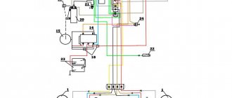
Wiring diagram of Ant moto equipment
Hai! This wiring diagram of the Ant equipment will be useful to those who restore old Soviet scooters. On our website All about motorcycles, such biker mechanics will find many useful images, as well as texts with tips on tuning iron horses, etc.
This resource also provides news from the world of biker sporting events.
The famous domestic scooter has become a rarity these days. Only occasionally is he encountered on the endless roads of his great homeland. You can buy it for relatively little money. On this motorcycle site you can study the technical characteristics of this utility vehicle.
Explanations for the Ant Moto wiring diagram:
1) Direction indicators with bulbs. 2) battery (battery). 3) Scooter speedometer. 4) Speedometer dial illumination lamp. 5) Motorcycle ignition system spark plug. 6) Ignition system coil. 7) Ignition system capacitor. Mechanism for turning on/off high beams, as well as a sound signal. 9) Front parking light bulb. 10) Main lighting bulb (low/high beam). 11) Turn signal switch. 12) Sound signal playback device. 13) Scooter turn signal relay. 14) Switch. 15) Switch for night light bulbs. 16) Indicator light for generator operation identification. 17) Neutral gear identification indicator light. 18) Mechanism for identifying the inclusion of neutral gear in the gearbox. 19) Motorcycle clutch. 20) Dynastarter of the bike. 21) Interrupter for the ignition system of a Soviet scooter. 22) Ignition system lock. 23) Ignition system fuse. 24) Stop light switch/switch. 25) Moto relay regulator Ant. 26) Switch block. 27) Brake light bulb. 28) Rear marker lamp.
What's the result?
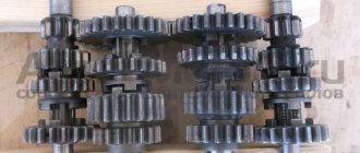
The crankshaft has been taken away - to say that it is worn out is to say nothing... The gearbox bearings, like the main bearings, have gone to the same place - to the crankshaft: in the trash. The gearbox, with the exception of one fork, did not cause any complaints. By the way, the clutch too.
Now the question is: what to do with all this junk? Buy a “plasticine” crankshaft from no one’s making and mold it into the engine. I was initially against this idea. In general, we found a used engine for a ruble and removed the crankshaft from it. Of course I had to tinker with him. Since the thread was clogged, I sharpened it and straightened it with a sharpening tool.
After correcting the threads, I checked the crankshaft for runout. There was no need to worry - the beating of the trunnions did not exceed one hundredth of a millimeter with a tolerance of three hundredths. By and large, it would have been necessary to replace the bushing of the upper head of the connecting rod, but time was running out and the bushing was not very worn. In all other respects, the crankshaft did not disappoint and this purchase can safely be called a success.
We decided to buy everything else: CPG, cylinder head, gaskets, seals, bearings, motor chain, etc. in the store. Although, by and large, the cylinder could have been bored out and that would be enough. But the owner did not want to wait, but in vain.
Connection
This vehicle, like all other light motor vehicles, has a two-stroke engine. Firstly, the combustible mixture in the engine cylinder is ignited, due to which the piston moves and then rotational motion is transmitted to the flywheel. I think that the Tula Motorcycle Plant should equip at least some of its vehicles with a modern starter from the SZA motorized stroller and an alternating current generator. The new circuit ensures reliable engine starting and sufficient battery charge.
I think that the Tula Motorcycle Plant should equip at least some of its vehicles with a modern starter from the SZA motorized stroller and an alternating current generator. All equipment has excellent insulation, eliminating the possibility of short circuits and harm to the driver.
For the most part, the Ant motorcycle is designed to transport large loads, so it was not equipped with special lighting parts.
Starting a cold and warm engine. Make a notch at a length of 4.mm. Close the contacts of the breaker when the piston is at TDC.
The electrical equipment of the Ant scooter is securely mounted on the body of the scooter and has good insulation, so the likelihood of a short circuit is negligible. We recommend reading:. →WIRING DIAGRAM TMZ ➧DISASSEMBLY, PRINCIPLES OF OPERATION
Spare parts price
Despite the fact that the production of the device stopped long ago, you can still find new spare parts for it that are produced by the industry. Some parts are imported, some come assembled. Supplied in sets:
- Clutch discs.
- Gaskets for power plant and gearbox.
- Nuts.
- Pipes.
- Levers.
The necessary parts can be found on the Internet using store catalogs. Prices for spare parts for the Ant scooter are fair. Here are some examples:
- Clutch disc – 400 rub.
- Kickstarter shaft – 1100 rub.
- Front shock absorber – 1600 rub.
- Gearbox seals – 100 RUR.
- Piston – 2500 rub.
- Gearbox – 14,000 rub.
- Wheel hub – 2000 rub.
Judging by the prices, the device is more than cheap to repair. This is an important operational property for people in rural areas.
Electrical circuit of the motor scooter Ant TG 200
To download the diagram click on the link below
The Ant TG 200 is based on its passenger car predecessor, the Tula T-200. The wiring diagram does not have complex components and is suitable for analogues of the Ant TG 200 scooter: TG-200F, TG-200I, TGA 200, TGA 200-01.
Download the electrical diagram of the Ant TG 200 scooter:
- Direction indicators
- Scooter battery
- Speedometer
- Speedometer backlight
- Spark plug
- Ignition coil
- Capacitor
- High beam and horn buttons
- Front side lights
- Low and high beam headlight
- Turn signal switch
- Sound signal
- Turn signal relay
- Switch
- Side light switch
- Battery charging indicator
- Neutral indicator
- Neutral sensor
- Clutch
- Scooter engine starter
- Breaker
- Egnition lock
- Fuse
- Brake light switch
- Relay regulator
- Switch block
- Brake light
- Tail light
Download the diagram
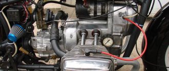
Design
Rice. 2. Placing blocks in a scooter.
The ignition coil is protected from overheating at low speeds by a composite additional resistor SE-107, which is partially blocked by the “Start” button when starting the engine. The ignition coil should be installed closer to the spark plug. The author placed all the rest of the modernization in a special box attached to the side of the scooter (Fig. 2).
Connecting this idiotic device to many is no more difficult than plugging in a vacuum cleaner, and maybe even easier. It all depends on the desire and level of technical literacy of the owner of the Ant. On the cover of the relay regulator there are letters indicating the terminals.
Part 3. Behind the wheel and Moto - separate components of scooters.
October 1957 - A little information on the dyno starter - a device that acts as a generator and starter on a motor scooter.
(Behind the wheel, 1 page). December 1957 - Description of the chassis of the Tula T-200 passenger scooter. (Behind the wheel, 1 page).
December 1961 - About the K-36 carburetor, which was used on Tourist and TGA-200 (Ant) scooters. (Behind the wheel, 2 pages).
August 1965 - About why the automatic ignition advance was removed. (Behind the wheel, 1 page).
July 1974 - A short article about shock absorbers and their design. In addition, you can find interesting operating diagrams of the shock absorber and general data on the models. (Behind the wheel, 3 pages).
Inverted version of the table.
January 1976 - Detailed information on Soviet tires. There is little to do with scooters, but the types of tires that were used on them are in the table. (Behind the wheel, 3 pages).
March 1976 - General information on spark plugs and some types of their malfunctions. There is a specific connection with scooters only when listing the models of spark plugs and the cars on which they were used. (Behind the wheel, 4 pages).
September 1977 - About the new K-62 carburetor, which replaced the K-36 model and began to be installed on Tulitsa scooters and almost all subsequent scooters and motorcycles of the Tula Machine-Building Plant. (Behind the wheel, 2 pages).
January 1979 - About batteries that were installed on scooters. (Behind the wheel, 1 page).
February 1991 - Carburetor K-65 which replaced the K-62. (Moto, 2 pages).
February 1991 - Some more information about tires. (Moto, 2 pages).
February 1992 - Construction of the front fork, which began to be installed on the Tula 5.951 off-road motorcycle. (Moto, 3 pages).
March 1992 — More about the battery. (Moto, 1 page).
April 1993 - Tula motorcycle gas tank 5.951. (Moto, 2 pages).
July 1993 - Information about old carburetors, of those listed on scooters K-28 and K-36 were installed. (Moto, 2 pages).
April 1994 - Construction of the Ant gearbox and drive suspension, i.e. rear axle as a whole. (Moto, 4 pages).
October 1994 - Information on lamps, in the table at the end there are types of lamps installed on Tula scooters. (Moto, 4 pages).
Same bonus - all articles in one file: part 3.pdf
Device and technical parameters
How to correctly set the magneto ignition on an Ant scooter
The design of the Ant scooter was quite simple and consisted of the following main parts:
- engine;
- frame;
- transmission and suspension;
- electrical equipment;
- brake system;
- body.
Such a simple design of the Ant 2M 01 scooter and its wide unification with the two-wheeled Tulitsa (Tula) model allowed the owners to carry out repairs themselves.
The TMZ Ant motor scooter had the following technical characteristics and operational parameters (data for modification of the Ant 2M motor scooter are given in parentheses):
- Drive – 3x2.
- Load capacity – 0.25 t (0.28 t).
- Engine: type – petrol two-stroke,
- ignition – electronic;
- number of cylinders – 1,
- volume – 0.20 l,
- cooling option – forced air,
- power – 11.0 l. With. (12.5 hp),
- carburetor - K-36G,
- fuel – a mixture of gasoline and oil (1/33).
- base – 1.78 m,
- type – mechanical,
- weight – 0.24 t,
Schematic diagram
As for the Ant's ignition system, you can upgrade it yourself. You can reduce the current passing through the contacts of the breaker using a transistor switch TK-102 (Fig. 1), which was used on the most common trucks in the past, ZIL-130, GAZ-53A, etc.
By reducing the current in this way by 6-8 times (to 0.3...0.8 A), we will make the breaker contacts almost eternal. The disadvantages of this solution include increased requirements for the cleanliness of contacts, since oil, dirt and dust caught between the contacts no longer burn out, as was the case with a conventional ignition system.
Rice. 1. Connection diagram of the transistor switch TK-102.
The use of a transistor switch makes it possible to use a higher-voltage B-114 ignition coil, which has a large secondary winding (41,500 turns). Since the voltage on the spark plug will increase from 17 to 25.30 kV, you can use a spark plug with a gap of up to 1.2 mm, which will save about 30% on gasoline.
Contactless ignition Ant, Tula (FULL set of BSZ Muravey 2.5)
How to correctly set the ignition on a VAZ 2106 with your own hands
ATTENTION: The manufacturer GUARANTEES the operation of the entire kit during initial installation. All equipment and its elements are 100% tested before shipping
It is extremely important to completely read the installation instructions, check for problems and short circuits in other electrical equipment, and use ONLY with a working battery. The warranty on consumables of the kit (switch, coil) is 14 days from the date of receipt
Although the commutator and coil have also been tested, it is impossible to guarantee a certain guaranteed period of their operation on an engine of this type, because They are designed by the factory for installation on 4T vehicle engines. If something does not work right away, then 99.9% the problem is due to incorrect installation, or damage caused by errors in the installation or operation of other equipment. During warranty service, all transportation costs for delivery of the kit to the service and back are paid by the buyer. You accept these terms and conditions upon purchase and agree to be bound by them. If you are not confident in your abilities or do not agree with the terms of the warranty, then please refrain from purchasing.
Contactless electronic ignition system Ant, Tula.
The optimal solution for high-quality engine operation is the use of so-called non-contact electronic ignition systems (BESZ).
The most important advantage of a contactless ignition system, compared to a contact one, is the supply of much more energy to the spark plug, which significantly increases the spark so necessary for fuel combustion. Thus, the combustion of the air-fuel mixture improves, which affects engine power.
No less important is the fact that the shape and stability of the pulses at all ranges of engine operation is significantly improved. This is achieved by using an optical sensor instead of a contact ignition system, which is needed to generate control pulses for the electronic switch. Thus, not only engine power and throttle response are improved, but fuel consumption is also reduced.
The third advantage and benefit of the contactless ignition system is its simplicity and low maintenance requirement. It needs to be configured once and that’s it. While the contact system is demanding in terms of maintenance and setup.
Composition of the contactless electronic ignition system kit Ant, Tula.
source
Basic faults
- Mechanical, caused by natural wear, combustion of windings, destruction of contact groups
- Structural, due to design features
- Malfunctions of the relay regulator that lead to dyno starter failure
The most unpleasant malfunctions are related to mechanics: combustion of windings, interturn short circuit, wear or destruction of the commutator. Other mechanical faults such as wear or sticking of brushes, contamination of the commutator, breakage or oxidation of wires and terminals can be eliminated quite easily.
Terminals
- The letter “B” indicates the battery connection terminal
- The letter "P" indicates the starter relay terminal
- The letter "C" indicates the starter terminal
- The letter “Ш” indicates the terminal of the shunt winding
- The letter "YaSH" designates the terminal of the shunt and armature winding
Diagnostics
The first sign that something has burned out, shorted or broken in the dyno starter or relay regulator is when, out of the blue, right in the middle of the road, your battery charge control lamp comes on.
If this happens to you, then the first thing you need to do is inspect the wires going from the dyno starter to the relay regulator, check the fuse, remove the cover from the relay regulator and at least visually determine the integrity of its elements, remove the rotor and see what’s wrong with the brushes and collector and if nothing suspicious is found there, turn to a very competent electrician for help.
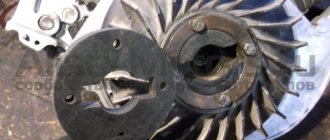
Disassembly
We remove everything that interferes with the removal of the rotor, hold the rotor by the fan with your hand and unscrew the nut
A good owner should have a washer and a lock under the nut. The bad one won’t even have a nut...
Remove the rotor from the crankshaft. The rotor can be removed either with a factory puller or with a homemade one - it makes no difference.
First of all, we inspect the rotor commutator and brushes. The commutator must not show any wear or damage. For example, this collector is just dirty and after we wash it, the dynostarter will start working again.
And some deer broke out the lamellas of this collector. Such a rotor will be difficult to help and easier to throw away. To prevent this from happening to your rotor, select bolts for the coupling for the magnet and the fan of the appropriate length, and do not put everything you have on hand there...
This collector was pulled up by something, the lamellas were shorted together and the dynostarter died. If you find a good turner, he will be able to sharpen the scuffs and the rotor’s performance will be restored.
There are situations when the rotor is dropped or the windings are hit. You understand that damage to the power windings will not improve the reliability of your scooter’s power supply system, so handle such devices very carefully and use pullers, and do not knock them down like tractor drivers with a hammer.
On this rotor, someone smacked the windings with relish.
Ant scooter engine repair
Details Created: 02/03/2014 07:28
Repairing an ant scooter engine must begin with the selection of a high-quality tool. You must have:
- flat wrenches;
- several Phillips and minus screwdrivers;
- a pair of hammers;
- wire cutters;
- pliers and long-nose pliers;
- set of socket wrenches;
- several files with different grain sizes;
- needle files;
- hacksaw for metal;
- several sheets of paper sandpaper of various grain sizes;
It is not critical if several tools from the list may be missing, it depends on the type of work being performed. However, it is advisable to have a complete set of tools, which, fortunately, is available in every garage. Some operations require special tools, which can still be made with your own hands from available materials. A set of these tools will be enough to perform routine maintenance and repair of the ant scooter engine.
Some people believe that repairs can be done with cheap sets of wrenches in terrible condition, licked screwdrivers, and other types of inappropriate tools. Sometimes they manage to repair the engine, but the quality of the work leaves much to be desired, not to mention the fact that it is simply stupid and dangerous. Thus, it is possible to cause both minor engine malfunctions, for example, damaged mounting bolts, and fatal ones - engine jamming or burning out of the cylinder block.
Disassembling and repairing an ant engine will not be difficult if you have high-quality tools and consumables. Replacement parts must be selected as high quality as possible, since some operations require accuracy down to hundredths of a millimeter. Repair depends on the diagnostics performed, wear of engine components, and non-standard operating modes.
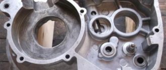
So, first you need to remove the engine from the frame and place it on a workbench, not forgetting to drain the oil before doing this. Then you need to remove the cooling covers and dynastarter. The dynastarter rotor can only be removed with a special puller; do not try to use a chisel or hammer. After this, you need to straighten the lock washer, unscrew the nut and remove the sprocket from the main gear. Next, turn the engine over, tighten all the bolts on the clutch cover, and tap the cover on all sides with a mallet, thus removing it. Remove the kickstarter shaft from the crankcase, unscrew the nuts on the clutch disc, and remove several clutch discs. For further work, you need to have a special puller, which can be made from an old clutch disc with a handle welded to it. We put the puller on the inner drum, remove the washer, hold the drum with the puller and unscrew the nut. Remove the lock washer from the crankshaft journal and unscrew the nut. We remove the basket with the sprocket and chain, remove the adjusting washer along with the outer drum bushing. We take the clutch rod out of the secondary shaft, then you need to turn the engine over, after which you need to shake out the ball and the second clutch rod. Unscrew the nuts and remove the cylinder head. We take out the cylinder, take out the retaining ring at the piston pin and push the piston pin out. Then you need to unscrew all the coupling bolts, turn the engine over and tap the engine evenly with a mallet until the crankcase halves come apart. Holding the engine in weight, take out the box and tap the crankshaft.
Thus, we completely disassembled the engine of the Ant scooter. Do not forget to diagnose all components during disassembly, such as: chain, cylinder mirror, quality of gaskets, all gears, bearings. It is necessary to check that there is no dirt, scuffing, metal shavings, or excessive play in the engine components.
- Back
- Forward
Search data for your request:
Paramoto-Forums Paramoto-Forum Question: what is bad about the ant's movement? Stoker Topic Author. Question: what is bad about ant movement? Compression ratio 9.
Search data for your request:
Schemes, reference books, datasheets: Discussions, articles, manuals:
Wait for the search to complete in all databases. Upon completion, a link will appear to access the found materials.
WATCH THE VIDEO ON THE TOPIC: → Charging diagram for TMZ motorcycles.
→WIRING DIAGRAM TMZ ➧DISASSEMBLY, PRINCIPLES OF OPERATION
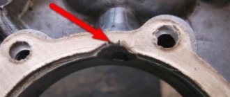
You need to remove and put away the batteries, the fact is that after installing the magneto, the ant will actually no longer need them! In the center of the lid is the manufacturer's logo. Carefully cut a through hole along this emblem, you will get a hole with a fairly large diameter. But when cutting, you need to leave at least 5 - 7 millimeters of body metal for attaching the magneto. Of course, it is better to cut a hole on a lathe, but if you don’t have one, you will have to work with a drill, over and over again, drilling holes around the intended hole with a thin drill.
When it breaks, then all this uneven disgrace is processed with a round file. You need to cut a donut out of metal, the outer diameter of which will be slightly larger than the distance between the magneto mounting brackets, and the inner diameter of the donut will be equal to the diameter of the hole made in the engine casing that was drilled!
We make a connection with the crankshaft. You need to try to fix the magneto drive to the fan; this needs to be done between its two halves, placing a strip of rubber. Rubber will remove vibration and noise. If something is not clear, here is a photo of remaking the ant and installing a magneto on it!
At the beginning, I would like to advise you to think about everything again, a magneto is not the best option for the Ant, the standard ignition system is no worse, and the magneto is not designed for long-term operation.
We cut out a hole of large diameter, carefully process the edges of the hole using a file. Next, we fix the spacer coupling, made independently, with four bolts on the rotor, mounting directly on top of the fan.
To install a magneto, you must first purchase or make your own adapters and an attachment for the rotors. How to install a magneto on an Ant scooter?
The procedure is as follows: Unscrew the engine protection cover. All actions take place on the right side of the engine. We unscrew and remove the air duct along with the cover; it covers the fan. It is this cover that needs to be altered a little; it is on it that we will install the magneto.
see also
Comments 10
If you still have a pressing question, send your email, I’ll send you a diagram for remaking the RR, very sensible, or look at the website motorscooter.ru
There is a dynastarter, and it has its own relay, with alternator-starter mode switching. It’s better, of course, to look for something native, but if you don’t have it, you can make something of your own if you have a specialist in electricity who understands. And the Lada transmissions, all these “tablets” and “chocolate bars” with old generators, work constantly. I installed the R-362 on a stationary diesel engine, as well as the R-356 on LUN generators, everything worked. Who is interested - www.reaa.ru/cgi-bin/yabb/YaBB.pl?num=1223834090.
You can’t put a relay from a Lada there, the generator design is not right.
VAZ CHOCOLATE, IF THE CURRENT IS 12 VOLTS, IF 6 VOLTS THEN THE CONTACT RELAY IS THE OLD LADY, WHICH IS ADJUSTABLE.
It’s better to look for something native, boo - they did it well before.
It won’t be a problem to find, you can hardly find analogues.
ready to sell this. write in PM
What happened to the original relay?
Is there a PP121 relay? It seems like the same thing should be on Tula... although I don’t know what’s easier to find.
Yes, in Tula it’s the same. order from the Internet or look on Avito in Russia, maybe there is something similar.
Contactless ignition Ant, Tula (FULL set of BSZ Muravey 2.5)
Topic of the section Homemade electronics, computer programs in the General Questions category; Hello everyone, I have an idea to install a spark ignition on my engine, I don’t have money to buy a specialized ignition, I want to make Forum Rules. Rules Advanced search. Forum General questions Homemade electronics, computer programs Electronic ignition circuit. Dear readers! Our articles talk about typical ways to resolve legal issues, but each case is unique. If you want to find out how to solve your particular problem, please use the online consultant form on the right or call the numbers provided on the website.
Cleaning the collector
Take a small screwdriver and clean out the dirt between the slats. The collector must be cleaned very carefully so as not to scratch the lamellas.
After cleaning, blow the collector with compressed air, wash it with clean gasoline and wipe it dry with a rag. It is best to wash the collector with a brush: wet the brush in clean gasoline and wash it until the dirt is completely removed. When the gasoline has completely evaporated, take a piece of some lint-free cloth, moisten it a little in gasoline and carefully rub the collector with the maximum possible force until it is perfectly clean.
Assembly
Gearbox: purpose, types of gearboxes, their advantages and disadvantages
I bought this main bearing. It seems to be our production. There are Chinese analogues in stores - they are more expensive, but I don’t know what their quality is... I try to buy something that may not be of such super-duper quality, but at least one that has been proven over the years.
The quality of production is such that there is essentially nothing to complain about. The price is quite reasonable - 350 rubles.
We press the inner race of the main bearing onto the right crankshaft journal. External - screw the stator flange of the dynostarter and press it into the crankcase until it rests against the flange.
We install the oil seal, retaining ring and main bearing into the left half of the crankcase. I'm installing a new main bearing. It is closed, but it doesn’t matter: we open it, wash out the factory grease and install it in the crankcase.
Lubricate all bearings and working edges of oil seals with clean engine oil. And very carefully, so as not to accidentally wrap the edge of the oil seal - insert the crankshaft into the left half of the crankcase, and knock out the crankcase guides by 5-6mm.
We degrease the crankcase connector, install a new gasket and install the second half of the crankcase.
Tighten the bolts and immediately so that nothing gets into the crankcase -. I'm installing a new piston, cylinder head and reed valve body. The piston one, like everything else, is of no particular origin - most likely Rostov, but clearly not Chinese. I didn’t want to get involved with this counterfeit, but the owner didn’t want to wait until they bore the cylinder and put a liner in the cylinder head and insisted on buying it. You see the prices for spare parts - it’s up to you to decide whether to contact this new product or not.
We install the second main bearing into the crankcase and secure it with a retaining ring.
To be honest, the task of removing the engine from the “Ant” frame is quite a bit of work... As for me, it’s easier to pull a diesel engine off a tractor than from this rattling thing... This is, of course, a joke. But seriously, removing the engine from the Ant is much more difficult and takes longer than from any other Soviet motorcycle.
"Golden" electric truck Ant
A delivery truck named “Ant” was announced in the summer of 2019. Its manufacturer is the well-known defense enterprise Tulamashzavod. And now the company announced the release of the first commercial samples. Previously, this plant produced three-wheeled cargo scooters, a pipe dream for owners of private houses with garden plots or simply summer residents.
Cargo scooter / Source: ks-moto
The scooter was produced from 1959 to 1995. But it received the name “Ant” in 1969, and before that it was called TG-200K or TG-200F. (modifications with body or van). Where did the name come from, symbolizing hard work and productivity?
Possibly from here. In 1966, the Ant mini-truck was created by two talented specialists, designer E. Molchanov and engineer O. Ivchenko.
Appearance and “X-ray” of the “Ant” car / Source: cardesign
An original car that has no analogues or competitors. The car was produced in scanty quantities, several copies were made at NAMI, the rest were made by home-made workers, fortunately information about the “Ant” was published in the magazine “Modelist-Konstruktor”. They did not produce such a car in Tula. It’s troublesome, but the scooter was already “torn off with your hands,” so why bother? But the plant did not disdain to take the original name.
And so, in our days, the reincarnation of “Ant” has taken place at Tulamashzavod. How successfully the “revival” went is for potential buyers to judge.
Ant electric truck / Source: car
The appearance of the electric truck attracts attention. But it turns out that it is not intended for driving on public roads, it is exclusively an inter-shop or warehouse transporter. Although, the manufacturer promises in the future to obtain permission for the Ant to travel on roads. The design of the machine is quite simple. A body and a two-seater cabin are installed on the frame, which consists of a tubular welded frame covered with plastic panels on top. Traction battery under the body. Main characteristics of the truck:
- Length/Width/Height 3470/1500/2100 mm;
- Curb vehicle weight 1000 kg;
- Load capacity 1000 kg;
- Maximum speed 22 km/h;
- Climbability up to 20%;
- Electric motor 5 hp;
- Traction battery capacity 350 Ah;
- On-board voltage 48 Volts;
- The mileage between charges of the traction battery is 70 - 90 km.
But the lead-acid battery provides energy to the electric motor. This is greetings from the middle of the 20th century today! It is clear that a lithium-ion battery is an expensive product. Maybe the manufacturer wanted to make their truck as affordable as possible and tried to reduce the price by abandoning expensive batteries? Nothing has happened, the price for the revived “Ant” is 1,250,000 rubles! How can one not remember that the direct analogue and competitor from Mordovia, the UMTET electric truck, is equipped with modern domestically produced traction batteries, but at the same time costs more than half a million rubles less.
Electric truck UMTET / Source: nix
All that remains is to sympathize with the exclusive distributor of “Ant”, Moscow. The queue of buyers for the “golden” truck is expected to be huge...
Checking the stator windings
We unscrew the stator mounting bolts, tap it around with a wooden mallet, remove it from the engine, turn it over with the wires towards you, switch the tester to the continuity mode, connect the tester probes to the two rightmost terminals of the windings, if the tester beeps, there is no winding breakage.
We do the same with the remaining two wires: put the tester into dialing mode, connect the tester probes to the ends of the wires, if the tester beeps, there is no winding break.
How to connect a dynastarter to a relay regulator?
Connecting the dynastarter to the relay regulator is not easy, but very simple. Didn't you know? And what exactly is there to connect? Some measly four wires. To some ancient relay. Well, okay, today I won’t rant too much, it’s better to get straight to the point.
Four wires come out of the dynastarter stator, which are directly connected to the relay-regulator in a certain order: the first (clockwise, if the dynastarter stator is placed with the brushes down) wire (thin) goes to the “YaSh” terminal, the second wire (thin) goes to the terminal “Ш”, the third wire (thick) goes through the fuse to the “YaSh” terminal, the fourth wire (the thickest) goes to the “C” terminal.
Dynastarter wiring harness suitable for relay regulator. A thin wire with a plug at the end is connected to the “Sh” terminal, a thin wire with a regular terminal at the end is connected to the “YaSh” terminal, a thick wire with a fuse is also connected to the “YaSh” terminal, the thickest wire is connected to the “C” terminal of the relay regulator
And here we have a relay-regulator in person to which all this junk is connected.