Checking the generator voltage regulator may be necessary when problems with the battery begin to occur. In particular, it began to undercharge or overcharge. When such a malfunction occurs, it’s time to check the generator voltage regulator relay.
The relay should turn off at 14.8 V
The task of this simple device is to regulate the voltage of the electric current that is supplied from the generator to the battery. When it fails, the battery is either not charged enough or, on the contrary, overcharged, which is also dangerous, since this significantly reduces the battery life.
Agree that the prospect of killing a battery because of one small part is not very good. This is why it is so important to monitor the operating condition of the voltage regulator (it can also be called a pill or a chocolate bar). But in order to properly check the voltage regulator, you need to know its type and several important features.
Types of Voltage Regulators
Having understood what types of these devices there are, what their features and properties are, a complete understanding of the procedures carried out during testing will come. This will also give the answer to what scheme, in what way and how to check the generator voltage regulator. There are two types of regulators:
- combined;
- separate.
In the first case, it is meant that the regulator housing is combined with the brush assembly directly in the generator housing. In the second case, the regulator is a separate unit, which is located on the car body, in the engine compartment, and wires from the generator go to it, and wires from it go to the battery.
A special feature of the regulators is that their housings are non-separable. They are usually filled with sealant or special resin. And there is no particular point in repairing them, since the device is inexpensive. Therefore, the main problem in this regard is to check the generator voltage regulator relay. Regardless of the type of regulator, the voltage symptoms will be the same.
Introduction.
Many years ago, I made a similar regulator when I had to earn extra money repairing radios at a customer’s home. The regulator turned out to be so convenient that over time I made another copy, since the first sample was constantly installed as an exhaust fan speed regulator. https://oldoctober.com/
By the way, this fan is from the Know How series, as it is equipped with an air shut-off valve of my own design. Description of the design >>> The material can be useful for residents living on the top floors of high-rise buildings and who have a good sense of smell.
The power of the connected load depends on the thyristor used and its cooling conditions. If a large thyristor or triac of the KU208G type is used, then you can safely connect a load of 200... 300 Watts. When using a small thyristor, type B169D, the power will be limited to 100 Watts.
Symptoms of a problem
So, in case of low voltage, the battery simply will not charge. That is, in the morning you will not be able to start the car, the lights on the dashboard may not even light up, or troubles will arise while driving. For example, dim headlights at night, unstable operation of the electrical system (problems with electrical appliances - wipers, heaters, radio, etc.).
In case of increased voltage, there is a high probability of a decrease in the electrolyte level in the battery banks, or its boiling. A white coating may also appear on the battery case. When overcharging, the battery may behave inappropriately.
Signs, malfunctions, repair of generator and voltage regulator
In addition, you can also identify the following signs of a faulty voltage regulator (in some cases, some of them may or may not be present, it all depends on the specific situation):
- the control light on the dashboard (although this may be a sign of other malfunctions, for example, that it has burned out, the contact has fallen out, and so on);
- after starting, the battery indicator on the dashboard does not go out, that is, there are obvious malfunctions in charging the battery;
- the brightness of the headlights becomes dependent on the engine speed (you can check this somewhere in a deserted place by placing the car against a wall and accelerating - if the glow changes, then most likely the voltage regulator is faulty);
- the car stopped starting normally the first time;
- constantly discharged quickly ;
- when the engine speed exceeds 2000 rpm, the indicators on the dashboard turn off ;
- the dynamic characteristics of the car decrease , this is especially noticeable at high engine speeds;
- In some cases, the battery may boil .
Add a link to a discussion of the article on the forum
RadioKot >Schemes >Digital devices >Protection and control >
| Article tags: | Add a tag |
Microcontroller relay regulator.
Author: Mitko Vitaly Sergeevich Published 02/11/2016 Created with the help of KotoRed.
The proposed device is intended to replace the standard voltage relay-regulator in the vehicle electrical system and is distinguished by the fact that the voltage it supports depends on the temperature of the battery. It does not require setup and uses a warning light on the dashboard to indicate certain malfunctions in the vehicle's power supply system. The disadvantage can be considered the need to intervene in the electrical wiring of the car, since the connection diagram of the new relay-regulator differs from the standard one. The device is not intended for use in cars with generators controlled via K-Line (Mercedes, BMW and some VAG cars). The relay-regulator diagram is shown in Fig. 1. Its basis is the ATtiny85-20SU (DD1) microcontroller, which can be replaced with ATtiny25-20SU or ATtiny45-20SU without changing the device circuit, its printed circuit board and microcontroller program. The programs attached to this article will not work with microcontrollers of other types.
Rice. 1. Relay-regulator diagram
Line PB0 (pin 5) of the microcontroller is configured as an output. On it, the program generates a signal to control the lamp on the car’s dashboard. Through the same lamp, a signal is sent to line PB1 (pin 6) of the microcontroller that the ignition is on. This input is protected from voltage surges by a zener diode VD2. In addition to what is indicated in the diagram, any 3.3...4.9 V zener diode in a suitable package is suitable here. Capacitor C6 suppresses the noise of the zener diode. The above-mentioned 12 V, 1.2…1.4 W signal lamp is connected to the collector circuit of transistor VT1, which amplifies the microcontroller signal.
The value of resistor R11, indicated in the diagram, can be reduced to 1 kOhm, but cannot be increased. This is due to the fact that, together with capacitor C6, it forms an integrating circuit that delays for some time after the transistor VT1 is turned off, the voltage at the PB1 input of the microcontroller reaching a high logical level. To accurately determine the on and off state of the car’s ignition switch, this time should not be longer than the delay available in the program. The maximum permissible resistance of resistor R11 2.2 kOhm was determined experimentally.
Line PB2 (pin 7) of the microcontroller, through an amplifier using transistors VT2-VT4, controls the excitation winding of the car generator. Please note that transistors VT2 and VT3 are powered not by 5 V, but by 9 V from the voltage stabilizer on the zener diode VD3. This is necessary to supply the gate of transistor VT4 with a voltage sufficient to open it completely, at which the resistance of the open channel of this transistor and the power dissipated on it are minimal. The 1N5239B zener diode can be replaced with any other with a stabilization voltage of 9...10 V.
A car battery temperature sensor is connected to line PB3 (pin 2) of the microcontroller. If thermistor RK1 is used as this sensor (I used a sealed one purchased on the website https://www.ebay.com, with long leads “NTC Thermistor temperature sensor 10K 1% 3950”), then together with resistor R10 it forms a measuring voltage divider . If the sensor is LM335 (BK1), which is connected instead of a thermistor, then the supply voltage is supplied to it through the same resistor. Capacitor C4 is a smoothing capacitor.
Please note that the dependence of the output voltage on temperature for a thermistor and an integrated temperature sensor are not the same, so the microcontroller programs when using these sensors must be different. In the first case it is ATTINY85_HTC_10K, in the second it is ATTI-NY85_LM335. The microcontroller configuration in both cases must correspond to table. 1. It matches the one originally set by the manufacturer.
Table 1
Line PB4 (pin 3) of the microcontroller is used as an analog input to control the voltage in the on-board network. Resistors R1, R6, R7, R9 form a divider of this voltage for supply to the ADC of the microcontroller. C1R8C3 is a filter that smoothes out the ripples of the measured voltage.
Resistors R2-R5 form a power filter with capacitor C2, and with resistor R17 - a ballast resistance for the voltage stabilizer on the zener diode VD3. Integrated stabilizer LM1117-5.0 (DA1) provides 5 V voltage to the microcontroller.
The device is assembled on a printed circuit board shown in Fig. 2. It is designed to accept size 1206 surface mount resistors and the same capacitors (except for oxide C2, C7 and C8). There are no special requirements for transistors VT2 and VT3. Those whose types are indicated in the diagram can be replaced with other low-power ones of the appropriate structure with a collector-emitter voltage of at least 30 V and in a SOT95 package. Instead of the BCX56, any medium-power npn transistor in the SOT-89 package with a permissible collector current of at least 1 A and a collector-emitter voltage of 30 V or more is suitable. With appropriate modification of the board, suitable transistors can be used in other cases. For example, VT1 - KT815 series, VT2 - KT315 series, VT3 - KT361 series.
The IRLR2905 FET has an on-channel resistance of 0.027 ohms, a maximum drain current of 30 A and a TO-252AA package. In its place, for example, an IRLR2705 transistor (0.04 Ohm, 20 A) can work, but it will generate noticeably more heat and require more efficient heat removal. Another possible replacement is the RFP50N06 FET (0.022 Ohm, 50 A). It is quite popular in automotive UMZCH, but has a TO-220AB body.
As a replacement for the LM1117-5.0 microcircuit, the parameters of many integrated voltage stabilizers +5 V are suitable. But all of them are incompatible with it in terms of pin assignments. Therefore, when replacing, you will need to make adjustments to the printed circuit board.
Diode 10A7 (VD1, installed outside the printed circuit board) can be replaced with any other diode with a permissible forward current of 10 A and a reverse voltage of at least 100 V.
The printed circuit board is made of fiberglass foil on both sides, but the printed circuit conductors are etched only on one side. The foil on the opposite side of the board is retained and connected to the common wire of the device. After etching, holes are drilled in the board. Then a heat sink plate measuring 72x42 mm is cut out of an aluminum, copper or brass sheet 1.5...2 mm thick - slightly larger than the board itself. Using the board as a template, four mounting holes are drilled in the plate (in Fig. 2, these holes are larger in diameter than others).
Intended for parts that are not connected to the common wire, the holes in the board are countersunk from the solid foil side with a large-diameter drill to remove the foil around them. The two lower (according to Fig. 2) mounting holes must be countersunk from the side of the printed circuit conductors. The leads of the parts connected to the common wire should be soldered on both sides of the board during installation.
After completing the installation of all parts and checking it, place a heat sink plate on the board from the side of the printed conductors. It should rest on the body of the VT4 transistor and on two 2.3 mm thick washers placed on the upper (as per Fig. 2) mounting holes. It is advisable to lubricate the contact point of the heat sink with the transistor body with thermal conductive paste. The board and heat sink are fastened with four screws and nuts.
After checking the finished product in operation, it is disassembled, the board is covered with several layers of moisture-proof varnish (required!), while protecting the surface of the transistor VT4 and contacts XT1-XT6 in contact with the heat sink from the varnish, and reassembled. The gap between the board and the heat sink can be filled with hot glue.
In cars equipped with an electric generator, the stator windings of which are connected in a star configuration to a three-phase rectifier bridge with six diodes, a new relay-regulator is connected according to the diagram shown in Fig. 3. But first you need to remove the standard regulator relay and battery charging control relay. The places where the chains break are marked with crosses in the diagram. Having disconnected the right (according to the diagram) signal lamp terminal from the car body, connect it, as shown in the diagram with a thickened line, to the ignition switch terminal. Diode VD1 (see Fig. 1) is not required in the case under consideration.
Rice. 3. Connection diagram for the new relay regulator
If the stator windings of the generator are connected by a delta, and the rectifier consists of nine diodes, then a new relay-regulator is connected to it according to the diagram shown in Fig. 4. Here, in addition to the wires that went to the old relay-regulator, you need to cut another one connected to the left (according to the diagram) terminal of the signal lamp.
Rice. 4. Connection diagram for the new relay regulator
Through diode VD1 (see Fig. 1), the excitation winding of the generator is powered when the ignition is on, but the car engine is stopped or running at low speed. In the absence of diode VD1, the generator will not start working when the engine starts.
Directly from the ignition switch (without a diode), voltage cannot be applied to the excitation winding, since in this case the running engine will continue to operate even after the ignition is turned off.
The temperature sensor is attached to the battery with adhesive tape on both sides, not forgetting to first degrease the mounting area. A small foam plate is glued to the side of the tape opposite the sensor and battery. It will protect the sensor from being heated by hot air in the engine compartment.
While the ignition is turned off, the microcontroller program “sleeps”. “Waking up” when it is turned on, it gives a “voltage below the specified” signal - the signal lamp blinks frequently. As soon as the generator voltage reaches the lower threshold value after starting the engine, the lamp will go out and the program will go into voltage stabilization mode. If its upper threshold value is exceeded, the program will set a low level on the PB2 line of the microcontroller, which will close the VT4 transistor and turn off the generator excitation winding. When the voltage drops below the lower threshold, the program will set the PB2 line to a high level, opening the transistor that closes the power circuit of the excitation winding. The voltage values of the upper and lower thresholds (turning on and off the excitation winding) depend on the temperature of the battery and are hard-coded in the program. They are listed in the table. 2.
There is a lot of debate about the voltage that needs to be maintained. Theoretically, at a battery temperature of -30 °C, the voltage should be 15.9 V. But as practice shows, this is too much for on-board electronics. And the voltage of 12.5 V with the battery heated to +50 °C is, of course, too low. Especially in summer when the air conditioner, radiator fans and other current consumers are running. This voltage causes temporary failure of the ABS system. For these reasons, it was decided to focus on the voltage range of 12.8…15 V.
If the voltage remains below the lower threshold for more than 10 s, the warning light begins to flash at a frequency of about 2 Hz. There is also an indication of a malfunction (short circuit or break) in the temperature sensor circuit - flashing of the signal lamp with a frequency of 0.5 Hz. In this case, the program keeps the voltage within 13.8...14 V. The device turns off when the power is completely turned off or when the power is removed from the signal lamp (the ignition is turned off).
Program files (AtmelStudio) and printed circuit board (Sprint-Layout 6). In the archive.
We ask questions here: https://radiokot.ru/forum/viewtopic.php?f=2&t=127157
Files:
RAR archive
All questions in the Forum.
| What do you think of this article? | Did this device work for you? | |
| 28 | 4 | 7 |
Reasons for failure of the relay regulator
The reasons for the failure of the voltage regulator may be:
- short circuit in the circuit, including interturn short circuit of the excitation winding;
- failure of the rectifier bridge (diode breakdown);
- reverse polarity or incorrect connection to the battery terminals;
- penetration of moisture into the housing of the regulator and/or generator (for example, when washing a car or driving in heavy rain);
- mechanical damage to the unit;
- natural wear and tear of the unit, including brushes;
- poor quality of the device being directly tested.
There are a number of simple methods for checking the regulator, regardless of whether the unit is removable or not.
The simplest way to check the generator voltage regulator
The simplest method of checking the regulator is to measure the voltage at the battery terminals with a multimeter. However, it is worth immediately making a reservation that the algorithm given below does not give a 100% probability of failure of the regulator. Perhaps the generator itself has failed. But the advantage of this method is that it is simple and there is no need to dismantle the device from the car. So, the algorithm for checking the generator voltage regulator with a multimeter is as follows:
- Set the tester to DC voltage measurement mode at a limit of about 20 V (depending on the specific model, the main thing is that it displays values up to 20 V as accurately as possible).
- Start the engine.
- Measure the voltage at the battery terminals in idle mode (1000...1500 rpm). If the regulator and generator are working properly, the value should be within 13.2…14 V.
- Increase speed to 2000…2500 rpm. In the normal state of the electrical circuit, the corresponding voltage should be about 13.8 (+-) 0.2 V.
- When the speed increases to 3500 rpm and above, the voltage should not exceed 14.8 V.
If during the test the voltage values are very different from those given, then most likely the machine’s voltage regulator is faulty. Remember that the voltage should not fall below 12V and should not rise above 14.8V.
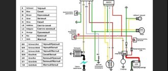
As mentioned above, the regulator can be separate or combined with a generator. Currently, almost all foreign cars, and most modern domestic cars, have combined relays installed. This is due to the specifics of their work and space saving.
Dinistor and 4 types of conductivity.
This device is called a trigger diode. Has little power. There are no electrodes in its interior.
The dinistor opens when the voltage increases. The speed at which voltage increases is determined by the capacitor and resistors. All adjustments are made through it. Works on direct and alternating current. You don’t have to buy it, it is in energy-saving lamps and is easy to get from there.
It is not often used in circuits, but in order not to spend money on diodes, a dinistor is used.
It contains 4 types: PNP N. This is the electrical conductivity itself. An electron-hole transition is formed between 2 adjacent regions. There are 3 such transitions in the dinistr.
Scheme:
We connect the capacitor. It starts charging with 1 resistor, the voltage is almost equal to that in the network. When the voltage in the capacitor reaches the level of the dinistor, it will turn on. The device starts working. Don't forget about the radiator, otherwise everything will overheat.
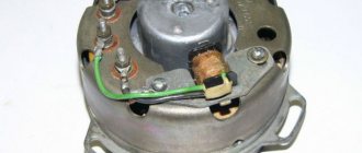
Checking the combined relay-regulator
Checking the VAZ 2110 voltage regulator
To perform the corresponding check, it is necessary to assemble the circuit shown in the figure. To do this, use a charger or power supply with an adjustable load (it is important that with its help it is possible to regulate the voltage value in the circuit), a 12 V light bulb (for example, from a turn signal or headlight, with a power of 3...4 W), a multimeter, and the regulator itself voltage (this can be from a Bosch, Valeo or other generator). It is advisable to have the wires used for switching with “crocodiles”.
Checking the voltage regulator of the generator 37.3701: 1 - battery; 2 — ground terminal of the voltage regulator; 3 - voltage regulator; 4 – terminal “Ш” of the regulator; 5 — output “B” of the regulator; 6 — control lamp; 7 — terminal “B” of the voltage regulator.
If you assemble a circuit in which the voltage is at a standard value of 12.7 V, then the light bulb will simply glow. But if you use a voltage regulator to raise its value to 14...14.5 V, then if the relay is working, the light should go out. Otherwise the regulator is faulty. That is, when the voltage reaches 14...14.5 V (depending on the model of the machine and, accordingly, the regulator) and above, the light goes out, and when it drops to the same level it lights up again.
It is important that the light does not go out until the voltage supplied to the regulator reaches 14 V. Otherwise, at idle, the generator will not be able to properly recharge the battery.
Checking the VAZ 2107 voltage regulator
Checking the voltage regulator on VAZ 2108/2109 cars
Until 1996, a VAZ 2107 with a 37.3701 generator was equipped with an old-style voltage regulator (17.3702). The verification procedure is given above. After 1996, a more modern generator of the G-222 brand was used (integrated regulator RN Ya112V (V1).
As you can see, the verification algorithm for all regulators is almost the same. The only difference is the cutoff values when the relay is activated.
Scheme number 1
There was a stabilized switching power supply that gave an output voltage of 17 volts and a current of 500 milliamps. A periodic change in voltage was required in the range of 11 - 13 volts. And the well-known voltage regulator circuit on one transistor coped with this perfectly. I added only an indication LED and a limiting resistor to it. By the way, the LED here is not only a “firefly” signaling the presence of output voltage. With the correct value of the limiting resistor, even a small change in the output voltage is reflected in the brightness of the LED, which provides additional information about its increase or decrease. The output voltage could be changed from 1.3 to 16 volts.
KT829, a powerful low-frequency silicon compound transistor, was installed on a powerful metal radiator and it seemed that, if necessary, it could easily withstand a heavy load, but a short circuit occurred in the consumer circuit and it burned out. The transistor has a high gain and is used in low-frequency amplifiers - you can really see its place there and not in voltage regulators.
On the left are removed electronic components, on the right are prepared for replacement. The difference in quantity is two items, but in terms of the quality of the circuits, the former and the one that was decided to be collected, it is incomparable. This begs the question: “Is it worth assembling a scheme with limited capabilities when there is a more advanced option “for the same money”, in the literal and figurative sense of this saying?”
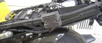
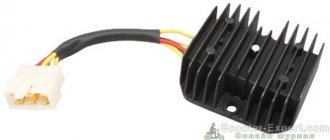
Checking an Individual Regulator
Checking the voltage regulator of the G-222 generator: 1 - battery; 2 - voltage regulator; 3 - control lamp.
As a rule, separate voltage regulators were installed on old cars, including domestic VAZs. But some manufacturers continue to do this to this day. The verification process is similar. To do this, you need to have a power supply with a voltage regulator, a 12 V light bulb, a multimeter and a directly tested regulator.
To check, you need to assemble the circuit shown in the figure. The process itself is similar to the one above. In normal condition (at a voltage of 12 V), the light bulb lights up. When the voltage value increases to 14.5 V, it goes out, and when it decreases, it lights up again. If during the process the lamp lights up or goes out at other values, it means that the regulator has failed.
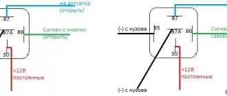
Checking relay type 591.3702-01
Relay test diagram type 591.3702-01
You can also still find a voltage regulator of type 591.3702-01, which was installed on rear-wheel drive VAZs (from VAZ 2101 to VAZ 2107), GAZ and Moskvich. The device is mounted separately and installed on the body. In general, the test is similar to that described above, but the differences are in the contacts used.
In particular, it has two main contacts - “67” and “15”. The first of them is a minus, and the second is a plus. Accordingly, to check it is necessary to assemble the circuit shown in the figure. The verification principle remains the same. In normal condition, at a voltage of 12 V, the light bulb lights up, and when the corresponding value increases to 14.5 V, it goes out. When the value returns to its original value, the light comes on again.
A classic regulator of this type is a device of the PP-380 brand, installed on VAZ 2101 and VAZ 2102 cars. We provide reference data regarding this regulator.
| Adjustable voltage at regulator and ambient temperature (50±3)° C, V: | |
| at the first stage | no more than 0.7 |
| on the second stage | 14,2 ± 0,3 |
| Resistance between plug “15” and ground, Ohm | 17,7 ± 2 |
| Resistance between plug “15” and plug “67” with open contacts, Ohm | 5,65 ± 0,3 |
| Air gap between armature and core, mm | 1,4 ± 0,07 |
| Distance between second stage contacts, mm | 0,45 ± 0,1 |
Testing a three-level relay
Regulated power supply
Some car owners install on their cars, instead of standard “chocolate bars,” three-level relays, which are technologically more advanced. Their difference is the presence of three voltage levels at which the battery power is cut off (for example, 13.7 V, 14.2 V and 14.7 V). The appropriate level can be set manually using a special regulator.
Such relays are more reliable and allow flexible adjustment of the cutoff voltage level. As for checking such a regulator, it is completely similar to the procedures described above. Just do not forget about the value that is set on the relay, and accordingly, check it with a multimeter.
Generator check
There is one method by which you can check the performance of a car generator equipped with a regulator relay 591.3702-01 with diagnostic elements. It is as follows:
- disconnect the wires that went to pins 67 and 15 of the voltage regulator;
- connect a light bulb to it (excluding the regulator from the circuit);
- Remove the wire from the positive terminal of the battery.
If, as a result of these actions, the engine does not stall, then we can say that the car’s generator is in order. Otherwise, it is faulty and needs to be checked and replaced.
Purpose of the voltage regulator relay on the VAZ 2106
As you know, the power supply system of the VAZ 2106 consists of two important elements: a battery and an alternator. A diode bridge is built into the generator, which motorists in the old fashioned way call a rectifier block. Its job is to convert alternating current into direct current. And to ensure that the voltage of this current is stable, does not depend on the rotation speed of the generator and does not “float” much, a device called a generator voltage relay regulator is used.
This device provides constant voltage throughout the entire on-board network of the VAZ 2106. If there is no relay regulator, the voltage will deviate abruptly from the average value of 12 volts, and it can “float” in a very wide range - from 9 to 32 volts. And since all energy consumers on board the VAZ 2106 are designed to operate under a voltage of 12 volts, without proper regulation of the supply voltage they will simply burn out.
Design of the relay regulator
On the very first VAZ 2106, contact regulators were installed. It is almost impossible to see such a device today, since it is hopelessly outdated, and it has been replaced by an electronic regulator. But to get acquainted with this device, we will have to consider the contact external regulator, since its example reveals the design most fully.
So, the main element of such a regulator is a winding of brass wire (about 1200 turns) with a copper core inside. The resistance of this winding is constant and is 16 Ohms. In addition, the regulator design includes a system of tungsten contacts, an adjustment plate and a magnetic shunt. There is also a system of resistors, the connection method of which can change depending on the required voltage. The highest resistance these resistors can provide is 75 ohms. This entire system is housed in a rectangular PCB body with contact pads for connecting wiring brought out.
Operating principle of the relay regulator
When the driver starts the VAZ 2106 engine, not only the crankshaft in the engine begins to rotate, but also the rotor in the generator. If the rotation speed of the rotor and crankshaft does not exceed 2 thousand revolutions per minute, then the voltage at the generator outputs does not exceed 13 volts. The regulator does not turn on at this voltage, and the current goes directly to the excitation winding. But if the speed of rotation of the crankshaft and rotor increases, the regulator automatically turns on.
The winding, which is connected to the generator brushes, instantly reacts to an increase in crankshaft speed and is magnetized. The core located in it is pulled inward, after which the contacts on some internal resistors are opened, and the contacts are closed on others. For example, when the engine is running at low speeds, only one resistor is used in the regulator. When the engine reaches maximum speed, three resistors are turned on, and the voltage on the excitation winding drops sharply.
Recommendations for increasing the service life of the regulator
In order to increase the service life of the voltage regulator, it is necessary to adhere to several simple rules aimed at implementing preventive measures. Among them:
- do not allow excessive contamination of the generator, periodically inspect its condition, and, if necessary, dismantle and clean the unit;
- check the tension of the alternator belt, tighten it if necessary (either yourself or in a car service);
- monitor the condition of the generator windings, in particular, do not allow them to darken;
- check the contact on the control wire of the relay-regulator, both its quality and the presence of oxidation on it;
- Perform periodic voltage checks on the vehicle battery with the engine running.
Following these simple rules will allow you to increase the resource and service life of both the generator and the vehicle voltage regulator.
Results
Checking the voltage regulator relay is not a difficult task, and almost any car enthusiast with basic repair skills can handle it. The main thing is to have the appropriate tools for this - a multimeter, a power supply with a voltage regulator (although you can connect it to a battery with a charger), a 12 V lamp and pieces of wires for mounting the appropriate circuit.
If during the inspection you find out that the regulator is out of order, then it must be replaced (repair work is usually not carried out). The main thing is not to make a mistake when choosing it and purchase the part that is suitable specifically for your car.
Generator device
The design of a car generator implies the presence of its own rectifier and control circuit. The generating part of the generator, using a stationary winding (stator), generates three-phase alternating current, which is then rectified by a series of six large diodes and the direct current charges the battery. Alternating current is induced by the rotating magnetic field of the winding (around the field winding or rotor). Next, the current is supplied to the electronic circuit through the brushes and slip rings.
Generator structure: 1.Nut. 2. Washer. 3.Pulley 4.Front cover. 5. Distance ring. 6.Rotor. 7.Stator. 8.Back cover. 9.Casing. 10. Gasket. 11.Protective sleeve. 12. Rectifier unit with capacitor. 13. Brush holder with voltage regulator.
The generator is located at the front of the car engine and is started using the crankshaft. The connection diagram and operating principle of a car generator are the same for any car. There are, of course, some differences, but they are usually associated with the quality of the manufactured product, the power and the layout of the components in the motor. All modern cars are equipped with alternating current generator sets, which include not only the generator itself, but also a voltage regulator. The regulator equally distributes the current in the excitation winding, and it is due to this that the power of the generator set itself fluctuates at a time when the voltage at the power output terminals remains unchanged.
New cars are most often equipped with an electronic unit on the voltage regulator, so the on-board computer can control the amount of load on the generator set. In turn, on hybrid cars the generator performs the work of the starter-generator; a similar circuit is used in other designs of the stop-start system.
The principle of operation of a car generator
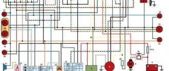
Connection diagram for the VAZ 2110-2115 generator
The alternator connection diagram includes the following components:
- Battery.
- Generator.
- Fuse block.
- Ignition.
- Dashboard.
- Rectifier block and additional diodes.
The principle of operation is quite simple: when you turn on the ignition, the plus goes through the ignition switch through the fuse box, the light bulb, the diode bridge and goes through the resistor to the minus. When the light on the dashboard lights up, then the plus goes to the generator (to the excitation winding), then during the process of starting the engine, the pulley begins to rotate, the armature also rotates, due to electromagnetic induction, electromotive force is generated and alternating current appears.
The most dangerous thing for the generator is the short circuit of the heat sink plates connected to the “ground” and the “+” terminal of the generator by metal objects accidentally falling between them or conductive bridges formed by contamination.
Next, the diode passes plus into the rectifier block through a sine wave into the left arm, and minus into the right arm. Additional diodes on the light bulb cut off the negatives and only positives are obtained, then it goes to the dashboard assembly, and the diode that is there allows only the negative to pass through, as a result the light goes out and the positive then goes through the resistor and goes to the negative.
The principle of operation of a car DC generator can be explained as follows: a small direct current begins to flow through the excitation winding, which is regulated by the control unit and is maintained by it at a level of slightly more than 14 V. Most generators in a car are capable of generating at least 45 amperes. The generator operates at 3000 rpm and above - if you look at the ratio of the size of the fan belts for the pulleys, it will be two or three to one in relation to the engine frequency.
To avoid this, the plates and other parts of the generator rectifier are partially or completely covered with an insulating layer. The heat sinks are combined into a monolithic design of the rectifier unit mainly by mounting plates made of insulating material, reinforced with connecting bars.
Next, let's look at the connection diagram for a car generator using the example of a VAZ-2107 car.