The scooter generator is one of the most important parts of the scooter; its malfunction means that it is impossible to continue moving; a spark simply will not appear. But if you doubt whether your generator is working or the reason for the malfunction of the scooter is in another part, it is strongly advised to check the generator. Many people don’t know how to check the generator on a 4t scooter, because this relates more to electrics, which scooterists hardly understand. Also, the verification problem will be in the absence of the main tool - a multimeter tester.
Experts identify several reasons for generator failure:
- short circuit formation;
- mechanical failure or wire breakage;
- significant reduction in rotor magnetization.
Basic faults
Before checking the generator for serviceability, we will consider the main faults. Practice shows that the generator breaks down most often on Chinese scooters, where the most common failure is the rotor losing its magnetization. The rotor often loses magnetization precisely because the scooter falls, that is, there is a direct impact. Also, if there is a nearby magnetic field, the rotor discharges.
Checking with a multimeter
To check the charge on the generator, you will need to use a proven method; the main task is to find out the output voltage. First of all, completely disconnect the generator from the scooter, then use the control device and start the engine. After starting, you can check the output voltage; the working generator should show at least 5V with the engine running.
The second stage is checking the output voltage of the switch; for this you will need a multimeter. The testing process begins by connecting the commutator to the generator stator, this is done using wires from both parts. Then you need to disconnect the wire related to the switch block from the ignition coil winding terminal. The next step is to connect two terminals - one goes to the engine ground, the second to the main wire on the ignition coil. This main wire is connected to the commutator.
After this, you will have to set the voltmeter to the main “direct current” mode and crank the engine with the kickstarter. By these actions we can find out the output voltage of the switch to the ignition coil. Then connect the switch wire to the coil. Under normal conditions, the output voltage of the scooter should be 200 V. For many, such a test may seem too complicated, because most of the terms are unfamiliar, and not everyone can use a multimeter, but if you really want, you can try and check the generator on a Chinese scooter.
Voltage check
Using a multimeter, you can find out the presence of voltage and its indicators, so you will have to start the procedure by removing some parts of the plastic located in the engine area. On the scooter you will have to find a large bundle of wires, which is located on the engines. Find the wire that should connect to the generator. The next stage is to measure the parameters of the circuit, the main task of which is to power the generator coil with electricity. Important: before this test you will have to disconnect the wiring from the generator, after which you can check the resistance. In normal operating condition, the generator should produce a resistance of 80 to 150 ohms. Deviation from the norm indicates a malfunction of the generator and the need to replace it. In some cases, the presence of incorrect resistance lies in the wiring, which is faulty. This can be determined by removing the generator and checking the coil resistance separately; if it gives optimal data, the reason is in the wires, in particular their short circuits.
Detecting the above faults is not an easy task; most scooter owners are not able to check the generator for serviceability, which is why they turn to specialists. If you have the financial means, it’s easier to buy a new generator, so you decide how to solve this problem yourself.
Greetings to all!
Somehow my voltage regulator (not a relay regulator, don’t confuse it) on a Chinese 4-stroke “fly”, I wasn’t planning on buying a new one, since the standard LV on all 4Ts is crap, I went to the Internet to look for a diagram. I didn’t have to search for long; I found a very simple and cheap option: a shunt RN. But for proper operation, it was necessary to disassemble the generator and disconnect the wire from ground, and lead it out with a separate wire.. Well, okay, I won’t explain further, because not everyone knows about electrics. In Chinese 4t, as a rule, these are the LVs: The circuit is crap, the efficiency is crap, the resource is crap. Let’s assemble this one (For a single-phase generator, in our case): For a three-phase one: We have two options for connecting a homemade LV, I won’t drag it out and tell you what and how: The first option (with alteration of the generator): 1) We disassemble the generator, remove the stator from engine and this is what we see: Important: Where it says “The mass needs to be soldered off” we solder a separate wire onto the winding and bring it out, this will be one end of the winding. The other end will be the white wire. That's it, we're done, putting the generator back together. It should turn out like this:
That is, we have two wires coming from the generator (Actually, there will be three of them, but we will need two).
I won’t describe the connection of the LV further, I’ll show you a better picture: Done, all that remains is to connect the yellow wire from the old LV to the “+” of the battery.
With this, the first version of the alteration is completed. Now our board. the network has a constant voltage. A relay for a scooter, or rather a relay-regulator, is a small but important part of all electrical equipment and the condition and durability of the battery and not only depends on it. This article will describe in detail the main purpose of the scooter relay, how it is connected to the electrical wiring of most mopeds, how to check its serviceability and other nuances.
A scooter relay regulator (or its second name is a voltage regulator) is an important and precise device that stabilizes the voltage at the required level, which is produced by the generator, for further distribution to consumers (headlight, signal, dimensions, turns, instruments, light bulbs and dashboard indicators and etc.). But the main consumer, the durability and performance of which depends on the relay regulator, is of course.
To put it simply, the relay regulator stabilizes and prevents the voltage from the generator from rising or falling above or below the norm (within 12 - 14.5 volts, depending on the speed), that is, it prevents the on-board voltage nets from going beyond the norm and damaging consumers, which are rated for 12 volts. So, for example, if the on-board voltage increases by only two volts, the service life of the moped’s incandescent lamps is halved.
In addition to the fact that the relay regulator of any scooter reduces the voltage from the generator from 30-35 volts (at maximum speed) to 12-14.5 volts, this device also rectifies the alternating current from the generator into direct current, which is required to charge the battery. And of course, if it weren’t for the relay-regulator, the battery and other devices would fail.
And if you do not connect the relay to the scooter (or the relay-regulator fails), then the light bulbs and other devices of the moped will begin to burn out. In general, the service life of an incandescent lamp on any serviceable moped is quite long, and the reason for failure and frequent replacement of lamps is, of course, a malfunction, or the absence of a relay regulator.
Also, the relay regulator on many scooters takes over all voltage surges that occur when the starter button, signal, headlights, ignition switch, signal and other consumers are turned on. And if it were not for the relay, the ignition switch contacts and switches in the scooter remote control would very quickly fail due to overheating.
The relay itself has a developed aluminum radiator that covers the device on all sides. The radiator is in contact with the plane of a powerful thyristor, which at the right moment (when the voltage drops) turns on, or turns off when the voltage increases, the relay contacts and thus switches the desired group of contacts at the right time.
For different models of scooters, each manufacturer selects a relay regulator individually, calculating it for consumers and the electrical circuit of their mopeds. Different manufacturers may have different terminal blocks (connectors), depending on the electrical circuit of different mopeds.
On mopeds from Chinese manufacturers, the relay regulator has five male terminals in the terminal block, but on most scooters from Japanese manufacturers there are only four terminals in the relay block. The Chinese (for example, such as “Viper Delta” or “Viper Activ” and others), in addition to having more terminals, also have a slightly larger body with a radiator than the Japanese (see photo).
But the design and basic operating principle of all relay regulators are almost the same - this is voltage switching using a powerful thyristor - turning off the voltage from the generator when the voltage rises above normal, and turning it on when the voltage drops.
Well, also, when the voltage on the pole pins of the battery decreases, the relay-regulator turns on the circuit and rectified voltage is sent to the battery for charging, and after the voltage on the battery (and, accordingly, the capacity) returns to normal, the relay immediately turns off the circuit supplying voltage charge to the battery.
If the generator is working properly, but the battery of your scooter is not charging, and the lamps and other consumers are constantly burning out, then you should definitely check the voltage coming to the consumers. And if the voltage is higher or lower than normal, then the voltage regulator should be checked and if it is faulty, the relay on the scooter should be replaced.
I will write how to check the relay-regulator itself a little later, but first I will write how to check whether the voltage supplied to the consumers of your scooter is normal.
How to check the voltage coming to the consumers of the scooter.
To check, we need a voltmeter that measures voltage in the range from 0 to 20 volts. It is best to use a multimeter (tester), which is sold in almost any electrical goods store. How to choose it? Having set the tester to measure DC voltage from 0 to 20 volts, you should prepare the probes - it is better to use wires not with probes but with alligator clips.
To check, just connect the clamps to the battery poles (plus to plus, and minus to minus) and pay attention to the voltage on the battery and remember it. Next, we start the moped engine and again observe the readings of the voltmeter (tester).
After starting the engine, if the generator and relay regulator of your moped are working properly, the voltage should increase at the battery poles, and when the engine speed increases, the voltage should increase even more (but not more than 14.5 volts at maximum speed), and when the speed decreases, the voltage should drop (but not less than 12.5 - 13.5 volts - depends on how the idle speed is set on your moped, the condition of the battery and how many consumers are turned on).
Thus, by adding gas and monitoring the voltmeter readings, you can visually observe the operation and serviceability of your scooter’s relay regulator. If, after starting the engine, your voltmeter shows the same voltage on the battery as it was before starting or less, or, on the contrary, an inflated voltage that is more than 14.5 volts at maximum speed, then most likely your voltage regulator is faulty and should be replaced.
I would like to note that on some modern mopeds that have modern maintenance-free batteries, the voltage at maximum speed should be no more than 13.8 volts, so before checking you should study the manual of your scooter and clarify the limits of the maximum and minimum voltage supplied to consumers ( with a working relay-regulator).
And one more nuance - it happens that when checking, the voltmeter readings fluctuate and it is impossible to check the charging voltage normally. The whole point is that the interference suppression resistor in the spark plug cap has failed or is simply not there (there are such caps). And in order to be able to check the charge voltage, you should replace the spark plug cap with a new one - this is clearly shown in the video below. It should be said that after the check described above, before going for a new relay on the scooter, you should check the relay-regulator specifically, using the same tester (multimeter) set to resistance measurement mode (ohmmeter). And this will be described in detail below.
Relay for a scooter - checking the serviceability of the relay regulator.
I have already described in detail how to check a car relay, and those interested can look at and read a detailed article about this. Well, here we will look at checking the relays of most scooters.
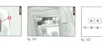
Scooter regulator relay - terminal block with terminals A, B, C, D. There should be 18 kOhm between terminals A and B; between terminals C and D there should be 33 kOhm; we change the probes on terminals C and D and there should be 42 kOhm;
And so, before checking, set the multimeter to the resistance measurement mode in kiloohms. Next, disconnect the voltage relay from the on-board network of your moped by pressing the latch and pulling the terminal block off the relay. There we will see 4 terminals (see photo on the left), which we mentally (or with a marker) mark with the letters A, B, C, D.
The condition of the relay regulator will be checked using the example of moped relays from the Japanese company Honda. The same relays (with the same parameters) are installed on most Chinese scooters, scooters and mopeds.
First, touch the tester probes to terminals A and B and monitor the ohmmeter readings. If the relay is working, the tester should show 18 kOhm. And if you swap the probes of the device and touch them to the same terminals A and B, then for a working relay the tester needle should be at zero (for a digital device it is one).
Next, we touch the tester probes to terminals C and D and look at the tester - if the relay is working, the ohmmeter should show a resistance of 33 kOhm. Next, we swap the tester probes on terminals C and D, and at the same time there should be a resistance of 42 kOhm for a working relay regulator.
All other combinations of terminal connections (for example, A and C, or B and D, or along the diagonal A and D or B and C) should not ring in a working relay, that is, there is a gap between them and the pointer device should show zero, and the digital device should show one - circuit break.
If the readings are different and not as described above, or when checking the voltage at the terminals of your battery while the engine is running, the voltage is too high or too low, then you should buy a new relay for the scooter and replace it.
And finally, just in case, I will publish for each contact of the voltage relay what should be the color of the wire that fits the relay terminal block from the moped's electrical wiring (see picture on the left).
This may need to be clarified, for example, if you got a moped with a relay that is not connected (or missing, or the terminal block is damaged, or the wires are unsoldered from it) and it is not clear where and what needs to be connected.
There are a lot of electrical diagrams for different mopeds on the Internet, but many beginners do not know how to read electrical diagrams and therefore I will show you more clearly below.
It should also be noted that some mopeds have a single-phase generator, while others have a two-phase generator. And accordingly, connecting the relay to the scooter is also done differently and this is clearly shown in the figure below.
Connecting a relay regulator with different generators
Figure number 1 shows a single-phase generator and how the wires (and their color) are connected to the relay-regulator block designed for a single-phase generator.
And Figure 2 shows a two-phase generator and how to connect the wires (and their color) to the voltage relay operating in tandem with such a generator.
The video below this article also talks about single-phase and two-phase generators.
I hope this article will be useful to novice repairmen, or simply owners of mopeds who have decided to check or replace the relay on a scooter, good luck to everyone.
No matter what kind of electric scooter you buy, you need to maintain it in good working order so that you can enjoy it for a long time. Maintenance and inspection of your scooter's electric generator is very important, so you need to know how to properly diagnose and maintain it. Electric scooters and motorcycles require virtually no maintenance. In this article we will talk about the main ways to check the performance of an electric generator.
Most electric scooters use a hub motor or electric motor that is conveniently integrated into the hub of the front or rear wheel. This does not change the basic design of the device. Since the motor is attached to the wheel, it can move that wheel very efficiently. The generators are easy to install and easy to access for maintenance and repair. When you turn off the electric scooter to return to running mode, the hub functions just like a traditional wheel hub, which connects the tire, rim and spokes. To keep your electric scooter running, you need to regularly maintain your device.
Hub engines have no disadvantages. First, they add extra weight to the wheel they power. And because they require additional wiring to deliver power, using wheels and changing tires is difficult. With this in mind, you will need to properly maintain your device.
Hub motor cones come in a variety of designs, and there are differences between designs. The smaller geared motor offers an increased rpm range but less power. Gear-type motors are usually large and heavy, but they provide more torque and power to an electric scooter. They are more efficient than gear motors. However, no matter what the design of the generators is, the principle of their operation is the same, which means the maintenance is the same.
Taking care of your electric scooter is key to maximizing the performance and usability of parts and components, especially engine components. If you know what kind of motor your device runs on, this article will help you know how to properly test your scooter electric generator.
Where should you start first? Check all electrical connections on your scooter. Most of them can be found in the battery compartment. Make sure they are all tightly connected to each other. At this time, your scooter's battery pack will automatically check the main and individual battery connections. Bundles of wires should not hang freely.
Usually the battery compartment on a scooter is located at the bottom of the floor
Test the generator by making a direct connection to the battery. You will need to find an insulated wire to perform this procedure and cut 2 pieces approximately 20cm long.
Electrics and electrical equipment of a scooter
Dedicated to all owners of Chinese scooters...
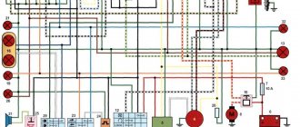
First, I would like to present a wiring diagram for a Chinese scooter.
Since all Chinese scooters are very similar, like Siamese twins, their electrical circuits are practically no different.
The diagram was found on the Internet and is, in my opinion, one of the most successful, since it shows the color of the connecting conductors. This greatly simplifies the diagram and makes it more comfortable to read.
(Click on the image to enlarge. The image will open in a new window).
It is worth noting that in the electrical circuit of a scooter, just like in any electronic circuit, there is a common wire . On a scooter, the common wire is the minus ( – ). In the diagram, the common wire is shown in green . If you look more closely, you will notice that it is connected to all the electrical equipment of the scooter: headlight ( 16 ), turn relay ( 24 ), instrument panel backlight lamp ( 15 ), indicator lamps ( 20 , 36 , 22 , 17 ), tachometer ( 18 ), fuel level sensor ( 14 ), horn ( 31 ), tail light/brake light ( 13 ), start relay ( 10 ) and other devices.
First, let's go over the main elements of the Chinese scooter circuit.
Egnition lock.
Ignition switch ( 12 ) or “Main switch”. The ignition switch is nothing more than a regular multi-position switch. Even though the ignition switch has 3 positions, the electrical circuit uses only 2.
When the key is in the first position, the red and black wires are connected. In this case, the voltage from the battery enters the electric circuit of the scooter, the scooter is ready to start. The fuel level indicator, tachometer, sound signal, turn relay, and ignition circuit are also ready for operation. They are supplied with power from the battery.
If the ignition switch malfunctions, it can be safely replaced with some kind of switch like a toggle switch. The toggle switch must be powerful enough, because the entire electrical circuit of the scooter is, in fact, switched through the ignition switch. Of course, you can do without a toggle switch if you limit yourself to short-circuiting the red and black wires, as the heroes of Hollywood action films once did.
1 is shorted to the housing (common wire). In this case, engine operation is blocked . Some scooter models have an engine stop button ( 27 ) to block the engine, which, like the ignition switch, connects the white- black and green (common, body) wires.
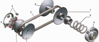
Generator.
The generator ( 4 ) produces alternating electric current to power all current consumers and charge the battery ( 6 ).
There are 5 wires coming from the generator. One of them is connected to a common wire (frame). The alternating voltage is removed from the white wire and supplied to the relay regulator for subsequent straightening and stabilization. The yellow wire removes voltage, which is used to power the low/high beam lamp, which is installed in the front fairing of the scooter.
Also in the design of the generator there is a so-called hall sensor . It is not electrically connected to the generator and there are 2 wires coming from it: white- green and red - black . The hall sensor is connected to the CDI ignition module ( 1 ).
Relay regulator.
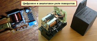
Regulator relay ( 5 ). People may call it a “stabilizer”, “transistor”, “regulator”, “voltage regulator” or simply “relay”. All these definitions refer to one piece of hardware. This is what the relay regulator looks like.
The relay regulator on Chinese scooters is installed in the front part under a plastic fairing. The relay-regulator itself is attached to the metal base of the scooter in order to reduce the heating of the relay radiator during operation. This is what the relay regulator looks like on a scooter.
In the operation of a scooter, the relay regulator plays a very important role. The task of the relay regulator is to convert the alternating voltage from the generator into direct voltage and limit it to 13.5 - 14.8 volts. This is the voltage required to charge the battery.
The diagram and photo show that there are 4 wires coming from the relay-regulator. Green is the common wire. We have already talked about it. Red is the output of positive DC voltage 13.5 -14.8 volts.
The regulator receives alternating voltage from the generator through the white wire to the relay. Also connected to the regulator is yellow wire coming from the generator. It supplies the regulator with alternating voltage from the generator. Due to the electronic circuit of the regulator, the voltage on this wire is converted into a pulsating one, and is supplied to powerful current consumers - the low and high beam lamps, as well as the dashboard backlight lamps (there may be several of them).
The supply voltage of the lamps is not stabilized, but is limited by the relay regulator at a certain level (about 12V), since at high speeds the alternating voltage supplied from the generator exceeds the permissible limit. I think those who have had their dimensions burned out due to malfunctions of the relay-regulator know this.
Despite all its importance, the device of the relay regulator is quite primitive. If you pick apart the compound with which the printed circuit board is filled, you will find that the main relay is an electronic circuit consisting of a thyristor BT151-650R , a diode bridge on 1N4007 , a powerful diode 1N5408 , as well as several wiring elements: electrolytic capacitors, low-power SMD transistors, resistors and a zener diode.
Due to its primitive circuitry, the relay-regulator often fails. Read about how to check the voltage regulator here.
Delta moped wiring diagram china
The electrical circuit diagram of Chinese scooters is shown in the figure:
As with other electrical connections, there is a common wire on all cube mopeds. In this diagram it is the negative tire running along the entire body. The corresponding battery terminal is also connected to the scooter's frame, ensuring that each electrical component's ground is in constant contact with the power source.
Electrics and electrical equipment of a scooter
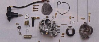
The main components in the 4t moped circuit are:
- central locking;
- battery charging source – generator;
- voltage limiter;
- spark formation and control systems;
- control elements for headlights, brake lights, turns;
- fuel level indicator in the tank.
All circuits are connected together using wiring.
Depending on the modifications and dimensions of the scooter, the instrument panel may include a tachometer - a device for monitoring the number of engine revolutions.
All of the listed nodes of the general scheme perform a strictly assigned role. Failure of at least one of them leads to the cessation of operation of the connected devices. Therefore, monitoring the serviceability of the main elements must be done every certain period for the purpose of prevention.
How to check the generator on a scooter?
The scooter generator is one of the most important parts of the scooter; its malfunction means that it is impossible to continue moving; a spark simply will not appear.
But if you doubt whether your generator is working or the reason for the malfunction of the scooter is in another part, it is strongly advised to check the generator. Many people don’t know how to check the generator on a 4t scooter, because this relates more to electrics, which scooterists hardly understand. Also, the verification problem will be in the absence of the main tool - a multimeter tester. Experts identify several reasons for generator failure:
- short circuit formation;
- mechanical failure or wire breakage;
- significant reduction in rotor magnetization.
Before checking the generator for serviceability, we will consider the main faults. Practice shows that the generator breaks down most often on Chinese scooters, where the most common failure is the rotor losing its magnetization. The rotor often loses magnetization precisely because the scooter falls, that is, there is a direct impact. Also, if there is a nearby magnetic field, the rotor discharges.
To check the charge on the generator, you will need to use a proven method; the main task is to find out the output voltage. First of all, completely disconnect the generator from the scooter, then use the control device and start the engine. After starting, you can check the output voltage; the working generator should show at least 5V with the engine running.
The second stage is checking the output voltage of the switch; for this you will need a multimeter. The testing process begins by connecting the commutator to the generator stator, this is done using wires from both parts. Then you need to disconnect the wire related to the switch block from the ignition coil winding terminal. The next step is to connect two terminals - one goes to the engine ground, the second to the main wire on the ignition coil. This main wire is connected to the commutator.
After this, you will have to set the voltmeter to the main “direct current” mode and crank the engine with the kickstarter. By these actions we can find out the output voltage of the switch to the ignition coil. Then connect the switch wire to the coil. Under normal conditions, the output voltage of the scooter should be 200 V. For many, such a test may seem too complicated, because most of the terms are unfamiliar, and not everyone can use a multimeter, but if you really want, you can try and check the generator on a Chinese scooter.
Using a multimeter, you can find out the presence of voltage and its indicators, so you will have to start the procedure by removing some parts of the plastic located in the engine area. On the scooter you will have to find a large bundle of wires, which is located on the engines. Find the wire that should connect to the generator. The next stage is to measure the parameters of the circuit, the main task of which is to power the generator coil with electricity. Important: before this test you will have to disconnect the wiring from the generator, after which you can check the resistance. In normal operating condition, the generator should produce a resistance of 80 to 150 ohms. Deviation from the norm indicates a malfunction of the generator and the need to replace it. In some cases, the presence of incorrect resistance lies in the wiring, which is faulty. This can be determined by removing the generator and checking the coil resistance separately; if it gives optimal data, the reason is in the wires, in particular their short circuits.
Detecting the above faults is not an easy task; most scooter owners are not able to check the generator for serviceability, which is why they turn to specialists. If you have the financial means, it’s easier to buy a new generator, so you decide how to solve this problem yourself.
Egnition lock
This component in the circuit of a 4-stroke 50cc or 150cc moped represents a switch. Moreover, it is multi-positional.
The lock performs the task of a central switch. It turns off the power to the entire scooter and turns the circuit back on when you turn the key. The larva itself is connected to a slider, which closes the corresponding contacts.
In the first position, the main wires interact - red and black. Current from the battery is supplied to the main circuits of the scooter. Since then it has been ready to launch.
The remaining positions close the black and white wire from the ignition module to the ground of the scooter. The operation of the motor is blocked by interrupting the spark supply from the coil. Depending on the modification, some models have a stop button in the electrical circuit. It performs the same function as the lock.
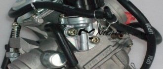
Generator
Owners of 50cc who are familiar with the design of the scooter will immediately understand the purpose of this device. It produces an alternating electric current that powers the moped when the engine is running. But the second main task is to charge the battery while working. That is, the battery ensures the operation of the devices when the engine is turned off, and then the generator takes on this task.
The connection is made according to the following principle. There are several wires coming from the generator. The negative tire is attached to the frame of the scooter. There is alternating voltage on the white wire, which is immediately sent for rectification and stabilization.
In the electrical circuit, the yellow wire powers the low and high beam lights. Additionally, a Hall sensor is located in the generator housing. Its task is to generate impulses to control sparking. It is not electrically connected to the generator; it is connected to a white-green and red-black wire. The sensor is connected to the CDI block.
How to check the generator on an alpha moped with a multimeter
Checking a scooter's generator is a fairly important and sometimes necessary procedure for every owner of this two-wheeled vehicle. Unfortunately, it can be difficult to establish its functionality, especially if you do not have deep knowledge in the field of electrical engineering, as well as the necessary tool - a multimeter tester . If you have such a tool, then before checking the generator you will need to familiarize yourself with the concepts of alternating and direct current, voltage, electrical impulse and tester indicators.
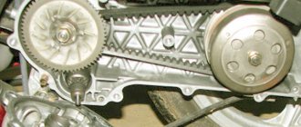
To check the generator on a scooter, you need to remove the plastic around the engine, and then measure the indicators - first of all, the voltage . You need to remove the casing as carefully as possible, otherwise you will damage the fastening system.
Find the place where the bundle of wires comes out of the engine and move along it to the connector - the place where the generator is connected to the scooter’s on-board network. Then you will need to measure the resistance of the circuit that powers the generator coil. Disconnect the wiring from the generator and measure the resistance of the connector wires. In theory, the resistance in the coil should be from 80 to 150 Ohms. If during measurement deviations from these values are found, you should not immediately think about a malfunction.
Try removing the generator from the scooter and measuring the resistance of the coil itself by connecting the tester directly to it. When taking readings from the coil, carefully inspect the condition of its terminals - damage that leads to a decrease in resistance may be the cause.
If during diagnostics you find out that the coil resistance readings are within the normal range, then the cause of the malfunction most likely lies in the wires themselves, coming from the coil or at the output points. Check the wiring and make sure there are no shorts in the wires.
If, as a result of this, no malfunctions were identified, you should also measure the variable resistance at the terminals from the ignition unit. If, after checking the generator on the scooter, you do not find any problems, the reason for the poor operation of the generator lies in the ignition unit.
Relay regulator
This is the same rectifier that converts alternating voltage to direct voltage, with a range of 13.5-14.9 V. C
.
The regulator is located under the plastic cover of the scooter at the front. It is attached to a metal backing for better heat dissipation.
The main circuits of the relay circuit are:
- The green wire is common.
- Red – output of converted and stabilized voltage within the established limits.
- White and yellow – AC input to the regulator. Due to electronics, the voltage is converted into powerful impulses. The yellow wire supplies power to a heavy load on the on-board network - headlights and instrument panel lighting.
The current for lamps is not stabilized, but is limited to acceptable values. At high generator speeds, the voltage goes beyond the operating ranges of the lamps, which leads to their burnout. The situation is very familiar to those who have encountered faulty relay regulators.
Because of one unit, you can lose all the light bulbs in a matter of seconds, so you should monitor the on-board voltage regularly.
Signs that a check is needed
If the battery on your scooter often runs out, and it is still quite new, this means that there is a problem with the operation of the relay regulator. As practice shows, it burns out quite often. If the device is faulty, the battery stops charging completely and loses its capacity. This means you won’t be able to start the scooter with a button; you’ll have to start it with a kickstarter.
Another characteristic sign of incorrect operation of the device may be the frequent burnout of incandescent light bulbs. They themselves are durable and have a good durability, but are quite sensitive to voltage changes. This happens because the optimal voltage in the scooter network is considered to be 12-13 V. Increasing this value even by 2 V reduces the service life of electronics and components by 2 times.
The greater the deviation from the norm, the greater the likelihood that something will burn out in the scooter. Therefore, when starting the scooter from the starter due to a power surge and a faulty relay, the bulbs usually burn out.
Signs of a malfunctioning regulator are identical for all models of Chinese scooters. They are especially typical for charging relays for scooters of Chinese models with an engine capacity of 50 cc. Therefore, before making a decision to replace something in electronics, testing systems and devices should begin with the relay regulator.