The principle of operation of ignition in a 4-stroke scooter engine
Modern scooters are equipped with contactless systems.
They are considered the most reliable and easy to use, do not require complex connections, and provide a constant good spark on time. However, the setting is still important; even the presence of a spark does not always allow the fuel mixture to ignite, since its power also plays a role. The main reasons for the operation of the ignition system are quite simple: its task is to create a spark to detonate the fuel mixture. If this does not happen, you need to carefully examine each node and find out why the spark disappeared.
- In order to check whether there is a spark at all, you need to unscrew the spark plug and apply it to the engine ground; this can be done using metal objects that are not covered with paint.
You cannot hold it with your hand: if there is a spark, it can give you an electric shock, and the discharge reaches 40,000 volts, which the coil creates. The functionality of the spark plug is checked in this simple way: you need to attach the spark plug to the metal body of the engine and turn the starter - If the spark plug does not produce a spark, it must be replaced with a new one; You can also check it using a special device that can be bought at a car store. It is inexpensive, it is a faster and safer way.
- If the spark plug is working, but there is still no spark, you will have to use a multimeter, with which you can check the wiring of the scooter, find a break or a faulty element.
- You also need to check the generator. It is an important element without which the scooter will not work. You will need to measure the resistance: to do this, you need to disconnect the ignition coil from the wiring, then measure the resistance between ground and the generator. This is usually a black wire with a red stripe. If the resistance is normal, it will be about 80-150 Ohms. If the device malfunctions, the resistance will be significantly less or absent altogether.
- After this, you need to measure the resistance that the coil produces. To do this, a multimeter is connected to its terminals. One of the terminals is connected to the magnetic circuit. If there is no resistance, a coil malfunction is diagnosed. If it is there, but weak, it is worth checking the wiring or the place where the coil connects to it.
- If everything is in order, but there is still no spark, you will need to check the wiring: to do this, you need to select two points to which the multimeter will be connected. One of the points should be the switch or ignition coil, the second should be the generator block. The wires may either be broken or there may be a short circuit between them. If the circuit is fully operational, check the ignition unit. It rarely fails, so it is dealt with last, when more likely causes of failure have been excluded.
Broken ignition is the cause of engine failure
An incorrectly configured or faulty ignition often causes engine failure. It would be wrong to immediately climb into the cylinder and examine the insides of the scooter, especially since this will not solve the problem. Before touching the ignition system, you need to check for other reasons why the scooter may not work.
- The simplest thing is the lack of gasoline in the tank. Quite often, owners forget to refuel their vehicle, and such a trivial reason can be overlooked.
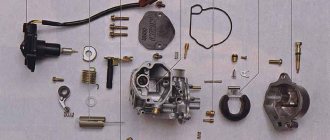
- The carburetor may be clogged, which prevents the formation of a mixture suitable for driving.
- The carburetor needs to be cleaned regularly, so it doesn't hurt to check whether fuel is flowing from it into the cylinder. It is possible that the fuel pipe is clogged. The jets and other parts of the device may become clogged with debris, which causes little fuel to flow or, conversely, the engine does not have enough air, and therefore it does not start.
- The scooter may also refuse to start if the fault is caused by spark plugs.
They may be wet or not produce a normal spark. It is advisable to have a spare set and check with it. In any case, the spark plug needs to be unscrewed and inspected. This way you can visually determine the condition of the spark plug on the scooter. - If, after checking all the components, you are convinced that they are in order, you can check the ignition system in the manner indicated above and proceed to setting it up if everything is in order with the technical part.
Ignition coil reliability parameters
Before purchasing a new reel, try to find out its reliability, according to reviews from its owners. Ask about the mileage that the device has withstood, whether the engine response and fuel consumption, maximum speed and CO emissions have changed.
The coil design must ensure:
- reliable insulation between windings and turns;
- high electrical resistance between the body and ground;
- strength of the case, especially plastic parts;
- absence of microcracks;
- reliability of electrical contacts and connections.
A high-quality reel can withstand temperatures up to 180°C.
All about the scooter ignition system and its operating principle
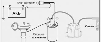
The most basic work concerning the ignition system is directly performed by the switch and the ignition coil. High voltage is created in the scooter's ignition coil itself and then applied to the spark plug. The principle of its operation is based on conventional electromagnetic induction. The scooter ignition coil consists of a primary and secondary winding. They are wound on top of each other, inside there is a special metal core. The primary winding of the ignition coil differs from the secondary in that several hundred turns are distributed on the first, but thousands of turns are distributed on the second.
First, the current follows through the primary winding of the ignition coil, creating a magnetic field in it. As work progresses, this current is interrupted, which leads to the disappearance of the magnetic field, but at the same time, the secondary winding of the coil has a high voltage. It is this high voltage, at a moment specified by the switch, that is supplied through the high-voltage wire to the spark plug using a spark plug cap. To prevent loss of current and prevent the high-voltage wire from overheating, it must have a large cross-section.
The spark plug electrodes are placed inside the combustion chamber. Through the cylinder head, when the spark plug contacts it with the help of a thread, earth is supplied.
If we talk about older models of scooters and mopeds, they have a magneto ignition system. Unlike them, modern scooters are equipped with a contactless ignition system, without a breaker contact. In this place there was always a weakness in the entire system, since frequent adjustment was simply a necessary measure. Today such an ignition system is not used.
The entire ignition system of the scooter is fully controlled by the switch. In some scooter models, the switch and ignition coil are combined in one unit, and if it fails, the entire unit must be replaced.
In addition to the electronics, the switch contains a terristor, which is an electrical breaker with three terminals. When voltage is applied to the terminal, the terristor acts as a conductor and the electric current flows freely from the main terminal to the next.
When the current drops to a certain level, the terristor acts as a conductor and when a certain value is reached it again acts as a breaker. During the break, a voltage pulse is again supplied from the hall sensor to the third terminal of the terristor and the process begins again.
An integral part of the switch system is the capacitor itself. It has the ability to accumulate electrical energy with a voltage of several hundred volts generated by the charging winding located inside the flywheel. When the terristor receives a control pulse emanating from the sensor winding, it takes on the role of a conductor, and the electricity previously accumulated in the capacitor is released through the primary winding in the scooter’s ignition coil. During this process, the ignition coil winding receives high voltage, which is the last link before being supplied to the spark plug.
The spark plug produces the required spark to ignite the mixture. This simple process happens in a split second. Such a scooter ignition system operates autonomously and does not require special settings on the part of the owner of the motorcycle.
Scooter electronic ignition device
The modern ignition system of a 4t scooter is designed as follows: the switch and coil, which are its main elements, supply high voltage to the spark plug, which generates an electrical discharge that can ignite the fuel. The coil generates high voltage due to electromagnetic induction. The switch is needed to distribute its interruption voltage at the right time. Inside there is an electronic circuit, a thyristor and three outputs for wires. At the right moment, the switch supplies voltage or turns it off.
The principle of operation of the scooter ignition system is as follows: the battery supplies voltage to the coil, which is often connected to a switch in one unit, the switch supplies voltage to the spark plug, and decides when to interrupt it. The mixture in the cylinders lights up at the right time. The correct operation of the engine and whether it will start at all depends on how the ignition is configured and set.
Switch
In many scooter models, the commutator is combined with a coil, so if one of the devices fails, the entire unit has to be replaced. Such spare parts are inexpensive.
Externally, the switch looks like a plastic box. Inside there is a microcircuit, a variety of electronics that cannot be repaired. In addition, there is a thyristor. The task of this element is to interrupt the electrical impulse at the right moment; for this purpose it has three outputs. When current enters one of them, the thyristor turns into a conductor, and the current moves from the input contact to the output. When a certain voltage is reached and the current drops, the pulse is interrupted, after which the Hall sensor returns the thyristor to its original position so that the signal arrives again at the third output. The process is repeated every time the voltage is applied again.
How to set the ignition on a scooter
With minimal experience, but good theoretical knowledge, you can set the ignition yourself. To do this, you just need to strictly follow the instructions below.
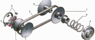
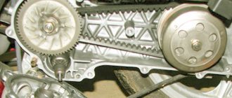
The most important part of tuning is to find the correct position for the timing sprocket to sit. In order to find it, they use special marks that are applied at the factory when assembling the engine.
The desired mark looks like the letter "T". In this position, the piston is at dead center. This is the extreme position after which the piston will return back. You need to rotate the rotor until the protrusion on the crankcase and the letter “T” coincide. This can be done using your hands or a kick starter. An electric starter does not need to be used.
To adjust, you need to align the “T” mark and the protrusion on the engine crankcase
Labels may look different on different scooters
If the piston has only moved down minimally, turn it further until the marks line up. It's not always possible to get the right position the first time. After they match, you need to study the other marks: they are located on the timing star. Usually these are three points or holes that are located on the outside of the star. They form a triangular shape if you connect them visually
Notice that one point is larger than the others. After adjusting the ignition, it should be on top, and the other two marks should remain opposite each other
They must stand horizontally.
Markings on the timing star
If the ignition is contactless, it is adjusted as follows. In order for the engine to run smoothly and correctly, you need to adjust the ignition of the mixture at the right moment. To do this, after all the tags are installed in the right places, you need to understand how the contactless principle works in general.
A special feature of the BZS is the presence of special sensors, a switch, and two types of ignition coil winding. When the sensor is closed using a rotor equipped with a magnet, a pulse is generated that enters the commutator, it pumps up the current coming from the generator and directs it to the primary winding of the coil. After this, the charge enters the secondary winding, where a high voltage is generated, with the help of which a spark appears, used to detonate the gasoline mixture. Adjusting the ignition is the alignment of the marks on the crankcase and the star. Usually you have to remove the valve cover.
After this you need to do the following:
- Labels are set in the manner described above.
- In order to set the ignition angle, you can release the stator mount and adjust it in accordance with the technical requirements of your vehicle.
- Make sure that the marks or holes are in the correct position.
Main elements of the system
Of course, the first thing to mention is the spark plugs. They are installed in the cylinder head, the electrodes come out from the inside. These are the elements that allow the air-fuel mixture to ignite. But with the help of spark plugs alone, the engine will not be able to run. It is necessary to monitor the position of the crankshaft in order to know in what position the pistons are in the cylinders.
For this purpose, an inductive sensor operating on the Hall effect is used. It is part of the design of another element - the ignition distributor. The sensor produces a pulse that is sent to the switch. This device allows you to amplify a weak signal to a voltage of 12 volts, and then apply it to a coil. A coil is nothing more than a simple transformer (step-up). Its secondary winding has a greater number of turns than the primary. Due to this, the voltage increases and the current decreases. The voltage in the BSZ is supplied to the spark plugs at a value of 30-35 kV (depending on the car model).
Ignition coil with spark plug cap 4T 139QMB,157QMJ,152QMI buy
1. Delivery to the address by courier service:
Delivery of orders is carried out by courier service from 9-00 to 21-00 from Monday to Friday (only in Moscow within the Moscow Ring Road).
Delivery of orders in Moscow is carried out within 1 - 2 working days, after the order is assembled, the cost is 400 rubles.
Delivery of orders within Moscow region is carried out within 2 - 3 working days, after the order is assembled, cost from 450 rubles. depending on the distance from the Moscow Ring Road, it is calculated separately by the company manager.
Delivery of orders in St. Petersburg is carried out within 2 - 3 working days, after the order is assembled, the cost is 500 rubles.
Delivery of orders throughout Russia is carried out within 3-10 working days, after the order is assembled, cost from 550 rubles.
Heavy (from 10 kg) and large-sized (plastic, etc.) parcels are sent only with 100% prepayment and the delivery cost is calculated separately!!!
2. PICKUP from the point of delivery of orders of the courier service SDEK, IML:
Minimum order amount -300 rub.
Delivery of orders to pick-up points (points of delivery) is carried out within 1 - 2 working days, after the order is assembled, cost from 210 rubles. depending on the selected delivery point.
As soon as the order arrives at the pickup point, you will receive an SMS on your mobile phone number (which you indicate when placing the order) informing you that the order (No....) is at the pickup point. The shelf life at the points of issue is 7 calendar days.
You can pay for your order upon receipt at the pickup point or by prepayment.
The cost of delivery to pick-up points in the regions is calculated for standard parcels weighing no more than 10 kg. and for an amount not exceeding 10,000 rubles. Heavy and large-sized (plastic, etc.) orders are sent only with 100% prepayment and delivery costs are calculated separately!!!
3. BY RUSSIAN POST:
Orders are sent by post within Russia upon prepayment.
Minimum order amount -300 rub.
If any of the goods you ordered are missing, incomplete, replacement, etc., the order will be sent only after your confirmation. Orders are assembled in 1-3 days, delivery time by mail ranges from 2 to 20 days, depending on the remoteness of the region. The postal number will be sent within 1-3 days after the order is sent!
4. Transport company: Business Lines, Energy, PEC:
Sending orders to TC throughout Russia is carried out on an advance payment basis.
Transfer to the shopping center takes place within 1 - 3 business days from the moment the funds arrive in the seller’s bank account. Delivery to shopping center in Moscow is free.
Payment for delivery to your city is made directly to the shopping center upon receipt of the order!
Attention: orders are sent to TK twice a week!
How to check the Hall sensor
It is recommended to carry out the test using a simple device that every driver can do with his own hands. He will need a resistance of 1 kOhm and a simple LED. A resistance is soldered to its leg, two pieces of any length of flexible wire convenient for operation are soldered to it, and the device is ready. Checking the Hall sensor is preceded by determining the presence of power supply to it:
- the distributor cap is removed;
- the plug box from the distributor is disconnected;
- the tester is connected to terminals 1 and 3, then the ignition is turned on.
If the car's electrical wiring is functioning normally, the tester will show a voltage of 10 volts or higher. After this, we connect the designed device to the same terminals - the LED lights up if the polarity has been chosen correctly. Otherwise, you need to swap the ends of the wires. The subsequent verification scheme is as follows:
- We do not touch the wire connected to the 1st terminal, but we transfer the end from the 3rd to the free 2nd terminal;
- rotate (manually or with a starter) the camshaft.
If you notice that the LED blinks during this process, then the ignition sensor does not need to be replaced. It is also possible to check the Hall sensor with a multimeter. It is connected to the ignition output contact, setting the device to voltmeter mode. The device arrow should move in the range of 0.4-3 Volts (an indicator of the health of the sensor).
How to check the Hall sensor
Malfunctions of the Hall sensor manifest themselves in different ways; even experienced specialists are not able to accurately determine the failure. There are a number of symptoms, but they indicate problems with the sensor indirectly, because These signs happen for different reasons:
- the engine does not start;
- at idle speed fluctuates;
- while driving, when the speed increases, the car jerks;
- The engine stalls for no reason.
If such symptoms occur, it is necessary to also check the Hall sensor. In addition to the method indicated in the article, there are several more. For example, the simplest thing is to ask someone for a working sensor and simply replace it on your car; if the problems go away on their own, then the sensor is faulty.
If you have a multimeter at hand, checking is easier than ever. To do this, you need to set the voltage measurement game mode on the device and test the indicators at the output of the sensor; if it is working properly, the voltage will vary from 0.4 to 11 V. Another common method involves checking in the absence of sparking (if there is power in the ignition system) and consists of in sensor simulation. The block is removed from the distributor and the ignition is turned on. Next, using a piece of wire, contacts 3 and 2 on the block are closed; if a spark appears on the central channel of the ignition coil, it means that the Hall sensor is faulty and requires replacement.
It will be interesting How to adjust the microphone sensitivity with your own hands
Another way is to check the existence of resistance on the sensor. To do this, you need to build a simple device, which consists of a 1 Kom resistor, a light diode, and flexible wiring. Solder a resistance to the leg of the light diode, and to it two wires of such length that it is convenient for operation (not short). Then remove the distributor cap, disconnect the distributor and the plug box. Then we check whether the electrical circuit is working properly. Therefore, we connect the electronics multimeter to the first and third terminals, then turn on the car’s ignition.
Under good conditions, the measurement on the device’s screen should be within 10-12 V. Then also connect the made mechanism to the same terminals. If you did everything correctly, the light diode will light up. Otherwise, you need to change the wiring places. Next you need to do this: do not touch the wire that is connected to the first terminal, do not touch the tip from the third terminal, transfer it to the free second terminal, turn the camshaft (by hand or with a starter). If the diode blinks when turning the shaft, this indicates that the sensor should not be changed.
Replacing the Hall sensor.
How to set the ignition on a scooter - contact system
Now we will learn how to set the ignition on a moped, walk-behind tractor or scooter. The scheme of actions depends on the type of spark creation system; it is known that there are only two of them - contact and non-contact (contact-transistor). Their main difference lies in the principle of operation. All old models of scooters, mopeds and walk-behind tractors had contact ignition. Currently, the second option is mostly used, since it is more advanced and tens of times more reliable.
Contact ignition is based on a mechanical interruption system. In the closed state, low voltage current flows through the primary circuit. When a contact in the secondary winding system opens under the influence of electromagnetic induction, a current surge occurs with a high voltage, and then the distribution block works with it. Ignition different from the norm may be early or late. It is displayed on a distributor; this device combines. Most often, this part is installed on the crankcase, but there may be other assembly specifics; you need to look at the instructions for the design and operation of the vehicle. The adjustment procedure is as follows:
- Having previously disassembled the crankcase, on the contact group we set the maximum permissible gap for a full circle of shaft rotation.
- Next, set the piston to a position whose distance from the engine dead center corresponds to the technical documentation.
- Now we loosen the stator mount and adjust it until the contact closes.
- Now we put all the details in place and admire the result.
Difference between stand and second scooter
Let's say you wondered how to check the switch on a 2T scooter. You have read this article and realized that simply using a tester will not give you the results you need. Therefore, you are faced with the question of whether to get a stand, or try to find another scooter to check. Many people are inclined to the second option, as it looks much simpler and more convenient. However, you should still consider the former, as it has several significant advantages. One of the biggest is the depth of testing: if with a second scooter you can simply test the functionality of the switch and some details of its operation, then on the bench you will have the full range of possibilities. Everything will be before your eyes, you will be able to use the tester on any element, set the number of revolutions you need in order to test at various load levels, and so on. You can even check the compatibility of switches with ignition coils, as well as come up with any checks and tests that your imagination allows you to do.
In general, you will have a complete flight of fancy. You will get the answer to not only how to check if the switch is working on a scooter. You will be able to get an answer to any question that concerns your vehicle. However, it’s worth saying right away that if you just decide to buy a scooter for a couple of years and then switch to a motorcycle or car, then you shouldn’t waste time and money. The stand is more suitable for those people who are confident that they will ride a scooter for many years.
Electrics and electrical equipment of a scooter
Dedicated to all owners of Chinese scooters...
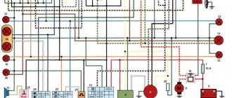
To begin with, I would like to present a wiring diagram for a Chinese scooter.
Since all Chinese scooters are very similar, like Siamese twins, their electrical circuits are practically no different.
The diagram was found on the Internet and is, in my opinion, one of the most successful, since it shows the color of the connecting conductors. This greatly simplifies the diagram and makes it more comfortable to read.
(Click on the image to enlarge. The image will open in a new window).
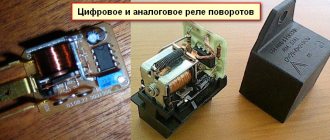
It is worth noting that in the electrical circuit of a scooter, just like in any electronic circuit, there is a common wire. On a scooter, the common wire is the minus (—). In the diagram, the common wire is shown in green. If you look more closely, you will notice that it is connected to all the electrical equipment of the scooter: headlight (16), turn relay (24), instrument panel backlight lamp (15), indicator lamps (20, 36, 22, 17), tachometer (18 ), fuel level sensor (14), horn (31), tail light/brake light (13), start relay (10) and other devices.
First, let's go over the main elements of the Chinese scooter circuit.
Egnition lock.
Ignition switch (12) or “Main switch”. The ignition switch is nothing more than a regular multi-position switch. Even though the ignition switch has 3 positions, the electrical circuit uses only 2.
When the key is in the first position, the red and black wires are connected. In this case, the voltage from the battery enters the electric circuit of the scooter, the scooter is ready to start. The fuel level indicator, tachometer, sound signal, turn relay, and ignition circuit are also ready for operation. They are supplied with power from the battery.
If the ignition switch malfunctions, it can be safely replaced with some kind of switch like a toggle switch. The toggle switch must be powerful enough, because the entire electrical circuit of the scooter is, in fact, switched through the ignition switch. Of course, you can do without a toggle switch if you limit yourself to short-circuiting the red and black wires, as the heroes of Hollywood action films once did
In the other two positions, the black and white wire from the CDI ignition module (1) is shorted to the housing (common wire). In this case, engine operation is blocked. In some scooter models, to block the engine, there is an engine stop button (27), which, like the ignition switch, connects the white-black and green (common, body) wire.
Generator.
The generator (4) produces alternating electric current to power all current consumers and charge the battery (6).
There are 5 wires coming from the generator. One of them is connected to a common wire (frame). The alternating voltage is removed from the white wire and supplied to the relay regulator for subsequent straightening and stabilization. The yellow wire removes voltage, which is used to power the low/high beam lamp, which is installed in the front fairing of the scooter.
Also in the design of the generator there is a so-called hall sensor. It is not electrically connected to the generator and there are 2 wires coming from it: white-green and red-black. The hall sensor is connected to the CDI ignition module (1).
Relay regulator.
Regulator relay (5). People may call it a “stabilizer”, “transistor”, “regulator”, “voltage regulator” or simply “relay”. All these definitions refer to one piece of hardware. This is what the relay regulator looks like.
The relay regulator on Chinese scooters is installed in the front part under a plastic fairing. The relay-regulator itself is attached to the metal base of the scooter in order to reduce the heating of the relay radiator during operation. This is what the relay regulator looks like on a scooter.
In the operation of a scooter, the relay regulator plays a very important role. The task of the relay regulator is to convert the alternating voltage from the generator into direct voltage and limit it to 13.5 - 14.8 volts. This is the voltage required to charge the battery.
The diagram and photo show that there are 4 wires coming from the relay-regulator. Green is the common wire. We have already talked about it. Red is the output of positive DC voltage 13.5 -14.8 volts.
The regulator receives alternating voltage from the generator through the white wire to the relay. Also connected to the regulator is a yellow wire coming from the generator. It supplies the regulator with alternating voltage from the generator. Due to the electronic circuit of the regulator, the voltage on this wire is converted into a pulsating one, and is supplied to powerful current consumers - the low and high beam lamps, as well as the dashboard backlight lamps (there may be several of them).
Ignition circuit components
The ignition circuit is an important part of the scooter's electrical system, without which it simply will not work without proper assembly. The circuit includes a coil, a spark plug, a switch, a generator, and a CDI ignition module. The latter looks like a small block, on one side it is plastic, on the other it is filled with compound. It is for this reason that when a unit fails, it is completely replaced without trying to disassemble it.
The CDI module has outputs for connecting five conductors. It is usually located quite close to the battery, can be mounted on the scooter frame or have a special cell. Most often, the CDI unit is located closer to the bottom of the vehicle, so it is not easy to reach. Without this element the system will not work.
Relay regulator
The relay regulator is colloquially called a stabilizer. This element is needed in order to rectify the voltage and stabilize it to the required level, which is suitable for the operation of the scooter’s electrical appliances. In Chinese and many Japanese models you need to look for it in the front of the vehicle, usually under the fairing. During operation, the radiator of the part becomes very hot, so it is placed where it can receive air cooling.
During operation, the generator produces alternating current, which is supplied first to the relay-regulator, and then moves on. The relay converts alternating voltage to direct voltage, in addition, it stabilizes the voltage to 13.5-14.8 Volts. If the voltage is less, the battery will not be able to charge; if it is more, there is a high risk of failure of the electrical system.
The regulator usually has 4 wires. They differ in color; in a standard diagram, the green wire is always ground. Red is under constant voltage. White supplies the regulator relay with the voltage supplied by the generator: this is alternating current. The yellow wire also goes from the generator to the relay regulator. The relay converts the voltage, turning it into a pulsating one. After this, the voltage goes to lighting fixtures, which are the most powerful consumers. Some models have an illuminated dashboard, additional lighting, running lights or other types of suspension. All this is powered by the same wire.
Pinout
If you have a 4T motor installed on your scooter, the pinout of the switch will depend on what type the scooter requires. For DC it will be as follows:
The leftmost terminal on top should connect to the generator sensor. Ground is connected to the terminal located under it.
You can tie the negative wire, for example, to the body of a moped; it is important that the part is metal. The upper terminal, located in the center, is connected to the wire leading to the ignition coil drive. The one located under it is also connected to the negative wire (ground). The wire from the ignition switch is connected to the upper rightmost terminal, which is needed to turn off the engine. The power wire is connected to the terminal located under it; it also comes from the ignition switch. If you have an AC type, the location of the terminals is the same, but they are connected differently:
If you have an AC type, the location of the terminals is the same, but they are connected differently:
- We move from left to right, first the top row, then the bottom.
- Here the wire from the generator sensor goes, as in the previous version.
- Next comes the ignition coil wire.
- And at the end there is a “silencer” for the ignition switch.
Bottom row:
- The first two terminals are the negative wire, “ground”.
- To the last remaining terminal we connect the power wire from the high-voltage winding of the generator. This point is the main difference when connecting an AC switch from a DC one.
Scooter Honda Dio AF 18 27
The Honda Dio AF 18 has a slightly different switch, made in Japan, which is why the pinout of the scooter is a little unique, and the mounts on the switch are different. It is connected as follows: from left to right, first the upper, then the lower terminals. Location:
- Hall Sensor.
- Ignition coil.
- Weight.
- Ignition lock.
- Power wire from a high voltage coil.
Yamaha Jog Scooter
Several types of generator can be installed on this type of motor vehicle. The most common option has 5 contacts, with wires already coming out of it. Therefore, if you have original wiring, you need to connect as follows:
- Orange should lead to the ignition coil and alternator.
- Black - to the ignition switch.
- Purple – Hall sensor.
- The remaining two wires are connected to the ignition coil.
Chinese scooters
Typically, such vehicles have standard switches, which were described above. The connection diagram depends on whether the AC or DC device is installed on your vehicle. It is worth remembering that different types of switches are not interchangeable.
Ignition switch and its features
The operating principle of supplying a spark to fuel in a moped is approximately the same as in a car. The task of this system is to ignite the mixture, which is supplied by the carburetor to the engine. The candle itself produces the ignition itself, but before that, other parts also participate in the process.
To activate the system, a so-called lock is used, from which a signal is sent to other parts. A key is required to use it on most vehicles. In the off position, the switch is shorted to ground using a special “leg”. In general, the design of the system on Alpha and other scooters and mopeds is not too different from that on cars. As mentioned above, in addition to the lock, the main role is played by the ignition coil and switch.
Device with high voltage wire
The video below demonstrates the repair of a lock (the author of the video is RECOVER PSR).
Classification of ignition systems
A variety of ignition systems can be structurally used in motorcycles, the most common of which are:
- Battery.
- From magneto.
- As a second plus remote coil (alternator).
With the third method, the spark increases in the spark plug; with the first, on the contrary, it weakens, which, as practice shows, is very important for high-speed motorcycle engines.
At Vwork. For motorcycle engines larger than 175 cm3, battery ignition is most widely used. Some motorcycles have both a magneto and a DC generator for greater reliability, which have magdino - separate drives. But this is not always economically feasible due to the high cost of the latter.
At Vwork. A motorcycle engine not reaching 175 cm3 uses a magneto plus generator system (common). Racing motorcycles (in some models) have a magneto installed.
On relatively cheap motorcycles, ignition from an alternator is widely used. It helps reduce the cost of electrical equipment and provides some advantages due to the separate use of the two above-mentioned drives.