Electrics and electrical equipment of a scooter
Dedicated to all owners of Chinese scooters...
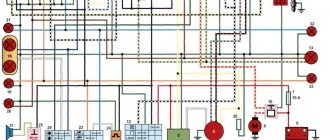
First, I would like to present a wiring diagram for a Chinese scooter.
Since all Chinese scooters are very similar, like Siamese twins, their electrical circuits are practically no different.
The diagram was found on the Internet and is, in my opinion, one of the most successful, since it shows the color of the connecting conductors. This greatly simplifies the diagram and makes it more comfortable to read.
(Click on the image to enlarge. The image will open in a new window).
It is worth noting that in the electrical circuit of a scooter, just like in any electronic circuit, there is a common wire . On a scooter, the common wire is the minus ( - ). In the diagram, the common wire is shown in green . If you look more closely, you will notice that it is connected to all the electrical equipment of the scooter: headlight ( 16 ), turn relay ( 24 ), instrument panel backlight lamp ( 15 ), indicator lamps ( 20 , 36 , 22 , 17 ), tachometer ( 18 ), fuel level sensor ( 14 ), horn ( 31 ), tail light/brake light ( 13 ), start relay ( 10 ) and other devices.
First, let's go over the main elements of the Chinese scooter circuit.
Egnition lock.
Ignition switch ( 12 ) or “Main switch”. The ignition switch is nothing more than a regular multi-position switch. Even though the ignition switch has 3 positions, the electrical circuit uses only 2.
When the key is in the first position, the red and black wires are connected. In this case, the voltage from the battery enters the electric circuit of the scooter, the scooter is ready to start. The fuel level indicator, tachometer, sound signal, turn relay, and ignition circuit are also ready for operation. They are supplied with power from the battery.
If the ignition switch malfunctions, it can be safely replaced with some kind of switch like a toggle switch. The toggle switch must be powerful enough, because the entire electrical circuit of the scooter is, in fact, switched through the ignition switch. Of course, you can do without a toggle switch if you limit yourself to short-circuiting the red and black wires, as the heroes of Hollywood action films once did.
1 is shorted to the housing (common wire). In this case, engine operation is blocked . Some scooter models have an engine stop button ( 27 ) to block the engine, which, like the ignition switch, connects the white- black and green (common, body) wires.
Generator.
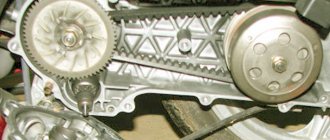
The generator ( 4 ) produces alternating electric current to power all current consumers and charge the battery ( 6 ).
There are 5 wires coming from the generator. One of them is connected to a common wire (frame). The alternating voltage is removed from the white wire and supplied to the relay regulator for subsequent straightening and stabilization. The yellow wire removes voltage, which is used to power the low/high beam lamp, which is installed in the front fairing of the scooter.
Also in the design of the generator there is a so-called hall sensor . It is not electrically connected to the generator and there are 2 wires coming from it: white- green and red - black . The hall sensor is connected to the CDI ignition module ( 1 ).
Relay regulator.
Regulator relay ( 5 ). People may call it a “stabilizer”, “transistor”, “regulator”, “voltage regulator” or simply “relay”. All these definitions refer to one piece of hardware. This is what the relay regulator looks like.
The relay regulator on Chinese scooters is installed in the front part under a plastic fairing. The relay-regulator itself is attached to the metal base of the scooter in order to reduce the heating of the relay radiator during operation. This is what the relay regulator looks like on a scooter.
In the operation of a scooter, the relay regulator plays a very important role. The task of the relay regulator is to convert the alternating voltage from the generator into direct voltage and limit it to 13.5 - 14.8 volts. This is the voltage required to charge the battery.
The diagram and photo show that there are 4 wires coming from the relay-regulator. Green is the common wire. We have already talked about it. Red is the output of positive DC voltage 13.5 -14.8 volts.
The regulator receives alternating voltage from the generator through the white wire to the relay. Also connected to the regulator is yellow wire coming from the generator. It supplies the regulator with alternating voltage from the generator. Due to the electronic circuit of the regulator, the voltage on this wire is converted into a pulsating one, and is supplied to powerful current consumers - the low and high beam lamps, as well as the dashboard backlight lamps (there may be several of them).
The supply voltage of the lamps is not stabilized, but is limited by the relay regulator at a certain level (about 12V), since at high speeds the alternating voltage supplied from the generator exceeds the permissible limit. I think those who have had their dimensions burned out due to malfunctions of the relay-regulator know this.
Despite all its importance, the device of the relay regulator is quite primitive. If you pick apart the compound with which the printed circuit board is filled, you will find that the main relay is an electronic circuit consisting of a thyristor BT151-650R , a diode bridge on 1N4007 , a powerful diode 1N5408 , as well as several wiring elements: electrolytic capacitors, low-power SMD transistors, resistors and a zener diode.
Due to its primitive circuitry, the relay-regulator often fails. Read about how to check the voltage regulator here.
How to check the Hall sensor
It is recommended to carry out the test using a simple device that every driver can do with his own hands. He will need a resistance of 1 kOhm and a simple LED. A resistance is soldered to its leg, two pieces of any length of flexible wire convenient for operation are soldered to it, and the device is ready. Checking the Hall sensor is preceded by determining the presence of power supply to it:
- the distributor cap is removed;
- the plug box from the distributor is disconnected;
- the tester is connected to terminals 1 and 3, then the ignition is turned on.
If the car's electrical wiring is functioning normally, the tester will show a voltage of 10 volts or higher. After this, we connect the designed device to the same terminals - the LED lights up if the polarity has been chosen correctly. Otherwise, you need to swap the ends of the wires. The subsequent verification scheme is as follows:
- We do not touch the wire connected to the 1st terminal, but we transfer the end from the 3rd to the free 2nd terminal;
- rotate (manually or with a starter) the camshaft.
If you notice that the LED blinks during this process, then the ignition sensor does not need to be replaced. It is also possible to check the Hall sensor with a multimeter. It is connected to the ignition output contact, setting the device to voltmeter mode. The device arrow should move in the range of 0.4-3 Volts (an indicator of the health of the sensor).
How to check the Hall sensor
Malfunctions of the Hall sensor manifest themselves in different ways; even experienced specialists are not able to accurately determine the failure. There are a number of symptoms, but they indicate problems with the sensor indirectly, because These signs happen for different reasons:
- the engine does not start;
- at idle speed fluctuates;
- while driving, when the speed increases, the car jerks;
- The engine stalls for no reason.
If such symptoms occur, it is necessary to also check the Hall sensor. In addition to the method indicated in the article, there are several more. For example, the simplest thing is to ask someone for a working sensor and simply replace it on your car; if the problems go away on their own, then the sensor is faulty.
If you have a multimeter at hand, checking is easier than ever. To do this, you need to set the voltage measurement game mode on the device and test the indicators at the output of the sensor; if it is working properly, the voltage will vary from 0.4 to 11 V. Another common method involves checking in the absence of sparking (if there is power in the ignition system) and consists of in sensor simulation. The block is removed from the distributor and the ignition is turned on. Next, using a piece of wire, contacts 3 and 2 on the block are closed; if a spark appears on the central channel of the ignition coil, it means that the Hall sensor is faulty and requires replacement.
It will be interesting How to adjust the microphone sensitivity with your own hands
Another way is to check the existence of resistance on the sensor. To do this, you need to build a simple device, which consists of a 1 Kom resistor, a light diode, and flexible wiring. Solder a resistance to the leg of the light diode, and to it two wires of such length that it is convenient for operation (not short). Then remove the distributor cap, disconnect the distributor and the plug box. Then we check whether the electrical circuit is working properly. Therefore, we connect the electronics multimeter to the first and third terminals, then turn on the car’s ignition.
Under good conditions, the measurement on the device’s screen should be within 10-12 V. Then also connect the made mechanism to the same terminals. If you did everything correctly, the light diode will light up. Otherwise, you need to change the wiring places. Next you need to do this: do not touch the wire that is connected to the first terminal, do not touch the tip from the third terminal, transfer it to the free second terminal, turn the camshaft (by hand or with a starter). If the diode blinks when turning the shaft, this indicates that the sensor should not be changed.
Replacing the Hall sensor.
Ignition circuit elements.
One of the most important electrical circuits in a scooter is the ignition circuit. It includes the CDI ignition module ( 1 ), ignition coil ( 2 ), spark plug ( 3 ).
CDI ignition module.
The CDI ignition module ( 1 ) is made in the form of a small box filled with compound. This makes it difficult to disassemble the CDI unit if it malfunctions. Although the modular design of this unit simplifies the process of replacing it.
There are 5 wires connected to the CDI module. The CDI module itself is located in the bottom of the scooter body near the battery compartment and is secured to the frame with a rubber clamp. Access to the CDI block is made difficult by the fact that it is located in the bottom part and is covered with decorative plastic, which has to be completely removed.
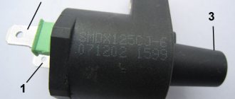
Ignition coil.
Ignition coil ( 2 ). The ignition coil itself is located on the right side of the scooter and is mounted on the frame. It is a kind of plastic barrel with two connectors for connection and a high-voltage wire output that goes to the spark plug.
What is a switch and why is it needed?
To put it simply, a switch is a certain module (according to Feng Shui - a DC CDI or AC CDI module) in which electrical energy is accumulated, which at the right moment is supplied in the form of a pulse to the ignition coil, where it is multiplied many times and jumps out in the form of an electric spark between the spark plug electrodes.
Depending on the type of commutator, the energy necessary for the formation of spawn can be accumulated in the commutator in two ways:
- On switches of the AC CDI type - the energy required to form a spark on the spark plug is first formed in the high-voltage coil of the generator and then, in the form of alternating current, enters the switch, where it accumulates in the capacitor and at the right moment is supplied to the ignition coil in the form of a pulse
- On DC CDI type switches, the energy required to form a spark on the spark plug in the form of direct current comes directly from the battery, where it is converted into alternating current, multiplied by voltage and supplied to the capacitor
The switch power coils on the generator look something like this. Some generator models have two, some have only one.
To ensure that the spark passes at the right moment, a magnetic induction sensor (in collective farm parlance - “Hall sensor”) is included in the design of the generator and the switch like it. A magnetic induction sensor is essentially a regular alternating current generator, only in miniature.
On the outside of the generator rotor there is a small protrusion, when passing near the sensor - a small alternating pulse is formed in the sensor windings, which is sent to the switch thyristor - the thyristor opens and the energy accumulated in the capacitor is supplied to the ignition coil
General diagnostics
If the moped engine stalls, you should first find out why this happened. Indeed, among the main reasons why an engine stalls on the road or refuses to start, only two are the lack of fuel or the inability to ignite the mixture. Often, during the first diagnosis, it turns out that there is gasoline in the tank, and the fuel mixture is supplied to the cylinders due to vacuum. And therefore, the reason for everything is that the spark on the scooter disappeared. To verify this, you simply need to unscrew the spark plug from its standard hole in the cylinder head. Then it is inserted into the cap, its end is applied to the motor body.
Next, start the engine and look at the electrodes. You should also check the element not only for the presence of a spark, but also for the condition of the electrodes. The candle can be dry or wet. If the electrode is wet, then the fault is not the power system and carburetor, but the lack of a spark. If there is no spark on a 4T scooter, the reasons may be different. We will look at the most likely ones below.
Delta moped wiring diagram china
The electrical circuit diagram of Chinese scooters is shown in the figure:
As with other electrical connections, there is a common wire on all cube mopeds. In this diagram it is the negative tire running along the entire body. The corresponding battery terminal is also connected to the scooter's frame, ensuring that each electrical component's ground is in constant contact with the power source.
Electrics and electrical equipment of a scooter
The main components in the 4t moped circuit are:
- central locking;
- battery charging source – generator;
- voltage limiter;
- spark formation and control systems;
- control elements for headlights, brake lights, turns;
- fuel level indicator in the tank.
All circuits are connected together using wiring.
Depending on the modifications and dimensions of the scooter, the instrument panel may include a tachometer - a device for monitoring the number of engine revolutions.
All of the listed nodes of the general scheme perform a strictly assigned role. Failure of at least one of them leads to the cessation of operation of the connected devices. Therefore, monitoring the serviceability of the main elements must be done every certain period for the purpose of prevention.
Cleaning the elements correctly
Every owner of motorcycle and automobile equipment should know how to properly clean spark plugs from carbon deposits. Most beginners try to restore parts themselves and then wonder why they don't work.
A better effect can be achieved if you use a sandblaster. If there is none, you can try cleaning with just sand. To do this, you should purchase an electric drill and sand in a bucket. Next, take the candle and clamp it in the drill chuck by the thread on the top. Large threads are wrapped with tape. The part is then lowered into the bucket and the tool is started. After some time, the electrodes and insulator will be cleaned. If the spark is lost for this reason, the scooter spark plug will work properly again.
Checking the generator sensor
The magnetic induction sensor is a key element of the ignition system. And if there is any suspicion of a problem with the ignition system, it should also be checked.
Switch the tester to AC measurement mode in the 2V range. With one probe we touch the ground, with the second probe we touch the white-blue or red-yellow wire coming from the sensor and turn the engine with the starter.
- If numbers flash on the screen, there is an impulse
- If the display shows zeros, check the sensor
Check by appearance
A serviceable part must be clean. Only slight soot on it is allowed. However, if the electrodes are melted or black, then the spark will not occur. Spark plugs deteriorate if the fuel mixture is too rich. If the insulator is white, but there are small black spots on it and signs of erosion on the electrode, this indicates overheating. This is also evidenced by melted electrodes and insulator in bubbles. If there are oil deposits on the part, it can be considered faulty and it is better to replace it with a new one. This simple DIY scooter repair will help you use this vehicle again.
Checking the power supply of the AC CDI switch
We switch the tester to the alternating current measurement mode for the 200V range. We touch the ground with one probe, the power wire with the second and crank the engine with the starter:
- If the supply voltage is at least 60-65V, the power supply is normal.
- If the voltage is significantly less or absent, check the generator. The supply winding of the generator in the mode of cranking the engine with the starter should produce at least 60V, and at average engine speeds - about 160V
Breaks in the spark plug cap
This reason can also be considered simple. If there is no spark on the scooter, you should remove the cap and then check its resistance level. After disconnecting the cap from the wire, take measurements. The multimeter probe is inserted into the spark plug hole. The other is attached to the pin that the wires go to. If the cap is working properly, the multimeter will show about 5 kOhm. On most modern scooters, the high-voltage wires, spark plug cap and ignition coil are made one-piece.
Checking the power supply of a DC CDI switch
If you have the wire of the high-voltage coil of the generator hanging idle (provided that everything was like this from the factory, and not after the intervention of some “guru”) - switch the tester to the DC measurement mode in the 20 V range. Look for the wire on the switch nutrition. Usually this is a black or gray wire; we touch the ground with one probe and the power wire with the other:
- If the display shows zeros, look for an open circuit in the power wiring.
- If the voltage is significantly less than 12v, look for oxidation or check if your battery is charged
- If the voltage is 12v or a little more, then everything is in order with the power supply and you can check further
Failure of ignition system components
This is not a common reason. But if the spark on the scooter disappears and there are no visible reasons, then it is necessary to test the switch, coil, and generator winding. You can check all these devices with the same multimeter. To make sure that the winding and pulse sensor are working properly, you need to connect one tester probe to the wire from the sensor, and the second to the engine crankcase.
A normally operating pulse sensor has a resistance of about 500 ohms. The generator winding resistance is two to three times less. If the multimeter shows infinity, then one of the components has failed. It should be replaced with a new one. If the value is less than 150-200 ohms, then the problem is in the supply coil, and therefore the spark is lost on the scooter. What to do in this situation? Buy a new generator. Such a device can be repaired, but if there is no time, it is better to simply replace it. Fortunately, the cost of the generator is low.
Connection diagram (pinout) of the scooter switch
This article will present connection diagrams (pinouts) for switches, the most popular scooter models in Russia.
Also, whenever possible, switches will be opened in order to study their contents in detail. We kindly ask readers who are well versed in electronics to express in the comments their assessment of the quality, design and tuning capabilities of the switches presented in this article.
Let's start with the switch model installed on Chinese scooters equipped with a 139QMB engine. Such a switch is of the DC-CDI type, and is quite rare in the “Chinese”.
This switch is of the AC CDI type and is installed on the vast majority of “Chinese” vehicles equipped with 139QMB, 157QMJ engines.
This switch after opening.
This switch is of the AC CDI type and is installed on Chinese mopeds “Alpha” and “Delta” equipped with a 1P39FMB engine.
“Silencer” - a wire that goes into the ignition switch connector or into the alarm connector; when the ignition is turned off, the wire shorts to ground and the scooter stalls.
The sensor is a wire coming from the magnetic induction sensor of the generator.
160V - the switch is powered by alternating voltage directly from the generator coil (drive).
12V — the switch is powered by constant voltage directly from the battery.
Switch
Even a beginner will find its location. This is a plastic box with a terminal block. Multi-colored wires are connected to it. The switch is necessary to control the operation of the ignition system. Both the switch and the ignition coil are made non-separable. If the element fails, then the problems can only be solved by replacement. The price of these parts is low - up to 500 rubles. Some service stations have special instruments that allow you to test the switch. However, in order to avoid searching for the appropriate services for a long time, the easiest way is to purchase a new switch. In the process of searching for the reason for the failure of the switch, you do not need to listen to “experts” who claim that the failure occurred due to driving without a battery. This is an unreliable opinion. The fact is that in modern scooters the power supply system and the ignition system do not depend on each other in any way.
Ignition switch and its features
The operating principle of supplying a spark to fuel in a moped is approximately the same as in a car. The task of this system is to ignite the mixture, which is supplied by the carburetor to the engine. The candle itself produces the ignition itself, but before that, other parts also participate in the process.
To activate the system, a so-called lock is used, from which a signal is sent to other parts. A key is required to use it on most vehicles. In the off position, the switch is shorted to ground using a special “leg”. In general, the design of the system on Alpha and other scooters and mopeds is not too different from that on cars. As mentioned above, in addition to the lock, the main role is played by the ignition coil and switch.
Device with high voltage wire
The video below demonstrates the repair of a lock (the author of the video is RECOVER PSR).
Spark plug gap
Spark plug gap is an important factor for proper engine operation. This parameter plays an important role in the process of spark formation, ignition of the fuel mixture, and efficient operation of the scooter throughout the entire speed range. The gap should be specified in the documentation for the specific scooter - this parameter may vary among manufacturers. Generally speaking, for most modern four-stroke Chinese and Japanese mopeds, the gap on the spark plugs is from 0.5 to 0.8 millimeters. It is necessary to monitor this parameter. For this reason, the spark may disappear. She leaves because the gap is too big.
Relay regulator
This is the same rectifier that converts alternating voltage to direct voltage, with a range of 13.5-14.9 V. C
.
The regulator is located under the plastic cover of the scooter at the front. It is attached to a metal backing for better heat dissipation.
The main circuits of the relay circuit are:
- The green wire is common.
- Red – output of converted and stabilized voltage within the established limits.
- White and yellow – AC input to the regulator. Due to electronics, the voltage is converted into powerful impulses. The yellow wire supplies power to a heavy load on the on-board network - headlights and instrument panel lighting.
The current for lamps is not stabilized, but is limited to acceptable values. At high generator speeds, the voltage goes beyond the operating ranges of the lamps, which leads to their burnout. The situation is very familiar to those who have encountered faulty relay regulators.
Because of one unit, you can lose all the light bulbs in a matter of seconds, so you should monitor the on-board voltage regularly.
What does the ignition system consist of?
Such a system on a scooter includes the following devices:
- battery
- starter
- current generator
- switch
- coil
- lock
- candle
- wiring.
Although all these elements have different sizes, costs and complexity of the device, their importance in the proper operation of motorcycle equipment is almost equal. The malfunction of just one of the above elements leads to a malfunction of the entire scooter.
Each of these devices has its own possible malfunctions. Let's discuss each device in order in which repairs should be made.
Spark plug
The most common breakdown in the ignition system (including why there is no spark on a scooter) is a faulty spark plug. The reasons are completely different: carbon deposits due to poor fuel quality (or oil); overheat; lean or enriched air-fuel mixture and others.
You can assess its condition visually by unscrewing it from the cylinder. The working color of the candle is brick. But white and black indicate problems in her work. The best way to solve the problem is to replace it with a new one. If this is not possible, then clean it with a brush, rags or heat it on a gas burner.
The spark test is carried out in the following order:
- The spark plug is unscrewed from the cylinder along with the tip.
- The spark plug body is leaned against a metal “mass”.
- The engine rotates with the crank or starter, and sparks should jump between the electrodes of the spark plug.
Remember! If a spark appears during replacement, then the ignition system is in order and you should move on to diagnosing other parts of the scooter.
Ignition coil
If the spark plug is replaced with a new one, but the scooter (moped) still does not start, we diagnose the coil. The coil is a device with two windings - primary and secondary. Visually, it is a barrel with two contacts and a high-voltage wire coming out.
The role of the coil is to increase the incoming voltage hundreds of times. The primary winding has two contacts as outputs. The secondary winding is located between the positive contact and the end of the high-voltage wire. Violation of the integrity of one of the windings leads to failure of the main task and, as a result, the absence of a spark.
It is better to start diagnosing the coil with the spark plug cap. Inside the cap there is an interference suppression resistor, which also fails. You can check it with a multimeter in resistance measurement mode. You need to connect probes to the unscrewed cap - one to the spark plug seat, the other to the end for the armor wire. The resistance is considered normal - within 5 kOhm. If not correct, replace the cap.
On modern ignition systems, the coil is made of a monolith with a wire and a tip. In this case, you need to test everything together. We connect one probe of the multimeter to the cap, the other probe - alternately to the two contacts of the coil. Determine the resistance on the primary and secondary windings of the coil.
Remember! The resistance of the primary winding should be in the range of 0.1 to 0.4 Ohm; secondary winding –6.35 to 9.7 kOhm. The values are the average for most scooters made in China. Therefore, for each model they need to be clarified in the reference book.
If the instrument readings do not correspond to the reference values, change the coil or spark plug cap, if removed.
Electrical wiring
Another useful principle - if you don’t know why the spark on the scooter disappeared, then check the wiring. The reason that the spark has disappeared is trivial - a broken wire, oxidation of contacts, connections, or broken terminals. This problem is typical for any scooter - be it China or Italy.
By removing the decorative plastic trim, you can fully inspect the condition of the wiring. Pay attention to the ground wire from the coil to the body. Wire contacts often oxidize, and this leads to a decrease in voltage in the ignition system. The same problem exists in the contacts of the wire connecting the engine and the moped frame.
Carefully inspect the sensor and switch contact terminals. The wires may not be in contact or have weak contact, as a result, current is lost. To eliminate it, clean each terminal from oxidation and carbon deposits, crimp the contacts and make sure that everything is firmly in their sockets.
Another unlikely problem (but quite possible) is a break in the ground wire from the ignition switch. The wire is used to stop the engine and switch the lock to the off state. If the wire breaks and shorts to the frame, even with the key turned, the spark disappears.
Switch
A switch is a complex electronic device that combines several elements. The main elements are a capacitor and a thyristor. A thyristor is an electronic device that interrupts the current flowing to the ignition coil. Reducing the voltage allows the thyristor to open a current path for the capacitor.
The capacitor serves to accumulate electrical charge and short-term release of charge at the required time. Like the ignition coil, the switch cannot be disassembled, so it is impossible to check the functionality of individual elements without special equipment. Therefore, all diagnostics boil down to replacing the device. If replacing the switch helped, that was the problem.
Advice! Since switch failure is a common reason when the spark is lost on a 4t scooter, it is recommended that everyone carry a spare switch in the glove compartment. This will allow you to get home if the switch breaks down on the road.
Generator
An expensive part in a scooter is the generator, even if it is China, or even Japan. It rarely fails, but it still happens. You can also diagnose the device using a multimeter by measuring the resistance on the generator winding.
Near the generator, locate two wires coming out of the engine crankcase. One of the wires is red and black (comes from the pulse sensor), the second is blue and white (the main winding on the generator). Test both of these devices.
To diagnose the pulse sensor, connect the multimeter probe to the red-black wire, and the second probe to ground. The nominal circuit resistance is 500 Ohms. Checking the generator winding is carried out according to the same principle, but the probe must be connected to another wire - blue and white. In this circuit the resistance is 150-200 Ohms. If the values shown by the multimeter do not correspond to the specified ranges, change the cause of the breakdown. Poor resistance means failure of the pulse sensor or generator winding.
How to set the ignition on a scooter
With minimal experience, but good theoretical knowledge, you can set the ignition yourself. To do this, you just need to strictly follow the instructions below.
The most important part of tuning is to find the correct position for the timing sprocket to sit. In order to find it, they use special marks that are applied at the factory when assembling the engine.
The desired mark looks like the letter "T". In this position, the piston is at dead center. This is the extreme position after which the piston will return back. You need to rotate the rotor until the protrusion on the crankcase and the letter “T” coincide. This can be done using your hands or a kick starter. An electric starter does not need to be used.
To adjust, you need to align the “T” mark and the protrusion on the engine crankcase
Labels may look different on different scooters
If the piston has only moved down minimally, turn it further until the marks line up. It's not always possible to get the right position the first time. After they match, you need to study the other marks: they are located on the timing star. Usually these are three points or holes that are located on the outside of the star. They form a triangular shape if you connect them visually
Notice that one point is larger than the others. After adjusting the ignition, it should be on top, and the other two marks should remain opposite each other
They must stand horizontally.
Markings on the timing star
If the ignition is contactless, it is adjusted as follows. In order for the engine to run smoothly and correctly, you need to adjust the ignition of the mixture at the right moment. To do this, after all the tags are installed in the right places, you need to understand how the contactless principle works in general.
A special feature of the BZS is the presence of special sensors, a switch, and two types of ignition coil winding. When the sensor is closed using a rotor equipped with a magnet, a pulse is generated that enters the commutator, it pumps up the current coming from the generator and directs it to the primary winding of the coil. After this, the charge enters the secondary winding, where a high voltage is generated, with the help of which a spark appears, used to detonate the gasoline mixture. Adjusting the ignition is the alignment of the marks on the crankcase and the star. Usually you have to remove the valve cover.
After this you need to do the following:
- Labels are set in the manner described above.
- In order to set the ignition angle, you can release the stator mount and adjust it in accordance with the technical requirements of your vehicle.
- Make sure that the marks or holes are in the correct position.
Reasons for failure of a 4-stroke scooter engine
If the engine, then the reasons can be very different:
1. There is no fuel supply to the combustion chamber.
2. Air supply is not adjusted.
3. There is no compression. Burnt and deformed valves do not provide compression. The reason for the lack of compression may be improper assembly or a malfunction of the cylinder itself.
4. The one responsible for the operation of the valves is faulty.
5. Defective
6. An ignition spark is not produced during the mechanical operation of the generator.
Checking the ignition coil with a multimeter (tester)
Closing coil and tester
There are several ways to test the ignition coil for functionality and identify the causes of the malfunction. One of them is to visually check for spark slipping between the spark plug and the motorcycle housings, but this can cause electronic failure.
The best way is to use a multimeter, a device that can be used to measure the voltage in electronics, such as a coil.
The check action plan is as follows: remove the ignition coil and clean it of dust and other dirt. We inspect it for damage, if everything is fine, we proceed to checking it with a multimeter. Both checking with a multimeter and general diagnostics of coil faults require certain knowledge, but in general terms the check consists of measuring the resistance of the windings. Before doing this, you should read the documentation for the coil and try to compare the measurement results with the nominal value.
The resistance of the first winding should be in the range of 0.3 - 2.1 Ohm (+ error of a couple of hundredths), the second winding should be from 5 to 10 kOhm (on some coils this value can exceed 15 kOhm).
If the resistance data of the first winding is exceeded, this indicates a winding break; an anomaly in the second winding indicates a violation of integrity and an interturn short circuit. A close value in the second case indicates a short circuit.
Detailed video instructions using the example of checking the ignition coil of a Ural motorcycle with a multimeter:
scooter 4t
In order for the rotation of the generator rotor and gas distribution shaft to correspond to the desired piston operating cycle, it is necessary to set their position according to the marks. On the magneto body there is a marker for the position of the dead center of the cylinder in the form of the letter “T”. The rotor can be adjusted manually, or using a kick starter. The position of the camshaft is determined by the marks on the timing sprocket. Three points marked on the star from the outside form the top of which should be directed to the extreme position from the piston. Adjusting the ignition consists of setting the correct position of the timing star.
Let's summarize the above
First, use a light bulb to check whether the switch generates a pulse or not:
- If the light is on, the switch and the modules that ensure its operation are 100% operational
- If the light does not light, it means that the switch or some module that ensures its operation has failed. And to understand for sure that the switch is faulty, we need to check all the modules.
- If the modules turn out to be serviceable, but the switch does not generate a pulse, then it is faulty and you can safely replace it with a new one
In conclusion, I would like to warn you against the temptation to take a known-good switch from someone and plug it in instead of your own. Yes, with this express method the faulty switch will be identified immediately. If it was really faulty, then with a known good one, a spark will immediately appear.
But how can we be 100% sure that the scooter’s wiring is in perfect order and no one has managed to put their smart personality into it before you? What if something shorted there or some tusk messed up the wiring in its own way and then the working switch will be in complete trouble. And then you will buy two switches - one for the person you asked for, the second for yourself. Do you need it?
Causes of ignition coil malfunction
Causes of ignition coil malfunctions
What could be the problem with a faulty ignition coil? But first of all, what signs of a coil malfunction can haunt a vehicle? You can understand this by the following signs:
- Misfire moments occur
- High coil temperature and fast heating
- Engine refuses to start
- Vehicle dashboard displays fault messages
Coil malfunction can occur for a number of reasons:
- Bad candles
- severe overheating
- Impact of the external environment
- Mechanical damage
Try to buy only high-quality spark plugs, this will get rid of problems with the ignition coil. It is also worth remembering that mechanical damage can occur due to strong vibration or oil leakage and contact with the coil, this can cause a short circuit. Strong vibrations can damage the insulation and cause breakdowns. As for temperature, the coil is initially designed to operate in high temperatures, but it is worth periodically allowing the coil, spark plugs and engine to cool down.