In order to guarantee a long service life for your electric scooter and have confidence in the safety of your electric vehicle, it is important to regularly inspect it, especially if you have not used it for a certain period of time. There is a decent selection of electric scooters on the market today; all technical work is carried out according to the same principle. We are talking about checking shock absorbers for deformations and damage, checking the effectiveness of the braking system, monitoring tire pressure and their condition. It may also be necessary to periodically replace the fuses and oil in the electric motor gearbox.
Most electric scooters made in China are similar in design, so their wiring diagrams are approximately identical. The main elements of an electric scooter circuit are batteries, a controller, a gearbox and an electric motor (usually in the rear wheel). It is possible to use two types of electric drive – chain drive and drive with a motor-wheel.
Upon purchase, each electric scooter is accompanied by a user manual, with a list of possible breakdowns and ways to eliminate them, a listing of parts and assemblies, as well as an electrical diagram. This information is extremely useful not only for professionals when performing complex repairs, but also for technically competent owners of electric scooters.
How to check the voltage regulator of a scooter for serviceability - theory and practice
The voltage regulator, or as it is also called, a relay regulator, has a clear purpose on modern scooters.
The voltage regulator stabilizes the current supplied from the generator so that it can then be distributed to the main consumers, such as light bulbs, sensors, relays, batteries, indicators, starting enrichment, etc. Simply put, the voltage regulator on a scooter is a kind of transformer in the electrical network , which lowers and stabilizes voltages to a level that promotes the normal operation of all devices and has certain limits beyond which voltage surges are unacceptable.
Other answers in this thread
#5 Oleg__UA
Active participant
mintaka (19.6.2007, 13:21) wrote: Nothing regulates here. More precisely, it regulates the complex interrelation of ALL generator windings.
Serega (19.6.2007, 15:04) wrote:
#7 mintaka
The battery is there, it has nothing to do with it, and without it everything was fine. As I understand it, you need to look at the load resistor under the beak? I already said, I took off the generator and looked at it, everything was there in a bunch.
#8 Serega
Wait with the resistors, try installing another voltage regulator first, most likely it.
Post edited by Serega: June 20, 2007 – 09:52
Serega (20.6.2007, 11:11) wrote:
ASTARD (19.6.2007, 15:17) wrote:
Limitations and procedure for modifying the turn relay
Installation of LEDs is possible only if the relays are digital. For cars of the VAZ or GAZ family, these are devices marked with the designation 494.3747 (for comparison: the designation for analog ones is 231.3747). When there is no marking, the relay class is quite simply determined by its dimensions, which are noticeably larger for the analog version. If the car only operates analog, you will have to purchase a digital one.
Appearance of digital and analog turn relays
The direction indicator is modified in the following sequence:
- The case is opened;
- The location of the chip responsible for the operation of the turn signals is determined: it is usually located to the right of the external board.
- The capacitor is replaced, which determines the frequency of the turn signal lamp blinking generator. The subtlety is that the capacitor capacity should be within 4.7 µF at 50 V operating voltage. Alternatively, you can install another capacitor; in most cases, the space inside the relay case allows this operation.
- Output parameters are monitored using measuring instruments. If the LEDs are functioning properly, the housing is installed in its original place.
As additional items you should purchase:
- P-channel transistor;
- A resistor from the above resistance range (if it will be soldered into the circuit and not a capacitor);
- LEDs (preferably red or orange).
Soldering of such a modernized version of the relay can be done using the usual hinged method, on top of the main circuit.
"Hazard warning light" on a scooter. UPDATED. (+VIDEO)
Some Chinese (as well as Japanese) scooters are equipped from the factory with an emergency alarm, or “hazard light,” as it is popularly called. In this article I would like to tell you how to make an emergency warning light on a scooter if one is not installed from the factory. So, let's get started. 1. Hazard alarm on/off button, any, but the smaller the better.
2. Three wires, the length depends on where the button will be located.
3. Half an hour of time.
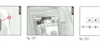
The first step: we disassemble the face where you have the instrument panel. We find the wiring harness going to the turn switch block and disconnect the plug. There are usually 8 wires - how do you know which one is which? To do this, we disassemble the switch block itself, and we see something like the following:
When the “right” contact is closed with the “common” one, the right turn signal works, the “left” one, respectively the left one. If you close all 3 contacts at once, everything will work together. But more on that later.
And now we need to introduce, so to speak, another button into the wiring, which, when turned on, closes 3 contacts at once, and when turned off, opens all 3 contacts. Otherwise, either the left or right side will constantly work, or when you try to turn on the turn signals on only one side, everything will work together. Having unbent the clamps, we remove the wires from the connector, in this case they are gray, orange and blue. It is to these same wires that we will solder to install the button.
First you need to strip the plug until the beige tint of copper is visible. Usually it is enough to scratch a couple of times with a knife or a file/sandpaper. We tin the plug so that there is a minimum amount of solder left on it.
Next, solder the wire to the plug. There is no need to use very thick or thin wires. Thin ones are not reliable, and thick ones simply won’t fit into the connector socket. We tin the wire and solder it onto the plug:
We do the same with the remaining two. Are you done? Assembling the switch block. We bend the clamps and insert the wires into the connector. Let's connect. Now you can check what we are getting: turn on the ignition, close all 3 wires and... voila:
Now we need a button. This type was chosen, Zhigulevskaya for 100 rubles:
In order for our wires to close and open as they should, we need contacts 1, 3 and 7 (all contacts are numbered, so you won’t get confused). It doesn’t matter how the wires are connected to them.
Wires can be soldered to these contacts, or you can find suitable plugs. I would advise finding a plug. Soldering is also an option, but if you need to remove the plastic, you will have to solder the wires. The plugs are like this:
We naturally need three pieces. Just like the previous ones, we clean them, tin them and solder them to our wires.
Soldered? Great! Now all that remains is to figure out where to embed the button, and then connect it.
How to cut a slot for a button exactly? First you need to find something round of suitable diameter. In this case, it’s... something... well, I don’t even know what to call it, with a diameter of 28 mm. This turned out to be enough:
We outline this “something” with something and start cutting it out. You can take a drill and a 1.5-2 mm drill and drill around the perimeter of the holes, then cut off everything that remains with a knife. I immediately cut along the contour with a knife.
Nissan Maxima QX 2 liter metallic › Logbook › The light is flashing (a hackneyed topic)
I know that the topic is not new and you need to look for it in the generator (90%). Here I want to understand by reading the opinions. I looked and looked for an answer in the Nissan community (Maxima\Cefiro). But I didn't find an answer. I should have looked longer. Maybe someone can provide a link. The car came out of the pit last night and the front struts and springs were changed. But he didn’t go far - 100 meters there and back. Why is that? I started the story here. I'll finish this topic there. I'm talking about something else. I left this morning and went to work, and arrived almost safely. The stand was disturbing, read about it above. It was in the evening. I got home, it was already evening. Let's be more precise - it's already dark. The low beam, like all electrics, works. I drove up to the gate of my house and saw this picture... Now carefully... At idle, the light burns evenly and does not blink or flicker. Short throttling, up to 3-4 thousand rpm. When the speed increases, the light stays on evenly. When the speed returns to normal idle, it flashes and dims. And at the very end, when the rpm is almost 600-800, the light flashes brighter, noticeably brighter. It manages to blink brighter two or three times. Then it burns evenly again - 500-600 rpm. And this happens all the time. The saga with the generator was big. During the repair, it was determined that the regulator had burned out - they replaced it (the brushes were good, but new ones were installed along with the regulator), and the bearings were also replaced. I installed it, everything works well, I checked it without a load (my mistake) using a voltmeter (Chinese machine) and it shows a smooth voltage, without surges. Under load - the low beam and dimensions are on, and the fan is set to low speed (so that the glass is blown). It gives out exactly everything! But this moment is not clear! Why does the light blink when the revs drop? I don't understand yet. Tomorrow I’ll experiment some more, take measurements under different loads with the device. Maybe something will become clear.
The epic with the stands is completed. Who missed it - here.
Method for checking the voltage regulator of a scooter
Chinese scooters are designed in such a way that their relay-regulator, which is also called a voltage regulator, often burns out. The voltage regulator is an electrical circuit with 4 terminals for connecting to the scooter's electrical network.
A malfunction of the voltage regulator leads to very disastrous consequences:
At first, the instrument panel backlight lamps and the central low/high beam lamp burn out. This happens due to the fact that the voltage from the generator is not limited to 12 volts, which leads to the lamps receiving an increased voltage of 16 to 27 volts and higher. The voltage supplied to the lamps fluctuates and depends on the engine speed. Even at idle, the lamps shine so much that they blind, although they should shine at half their maximum brightness.
If you do not remove the malfunction of the voltage regulator and leave everything as is (many do this - they just drive without lights), then over time the battery will fail because its charging voltage exceeds the permissible one. If the voltage regulator is faulty, the battery receives a voltage of more than 15 volts, while the standard charging voltage should be between 13.5 - 14.8 volts. All this leads to the fact that the battery begins to leak - acid begins to penetrate through the valves. This is noticeable to the naked eye. And although when the normal charging mode is restored, the battery restores its operation, its service life is sharply reduced.
Also, if the voltage regulator is faulty, the battery stops charging correctly and loses its capacity. Therefore, it is not possible to start the scooter with the button. You have to start it from kickstarter.
I think it’s now clear how important it is to change a faulty voltage regulator on a Chinese scooter.
How to check the voltage regulator on a scooter? It is best (and most reliable) to do this without dismantling the voltage regulator itself. We will need at least some kind of multimeter with a voltmeter function. Any ordinary DT-830 or similar will do. What should be done? It is necessary to measure the voltage at the output of the voltage regulator.
How to check the charging relay, voltage regulator
In this video I will show you how to check
two-phase
relay voltage regulator
, also called charging relay...
How to check if the relay regulator on a motorcycle is working?
How to check
Is the bike's alternator working? — .
All measurements were carried out on a Chinese scooter ABM Storm L ZW50QT-16.
To get to the relay-regulator, unscrew the front fairing in which the central headlight is installed. We find there on the frame a box with 4 terminals: red, green, yellow and white.
We put the scooter on the stand and start it. After some time, the engine operation stabilizes at idle. Next, measure the voltage between the green and red wires. We set the multimeter in DC voltage measurement mode to the limit of 20V. Here's a look at how you can do it.
The display should display a voltage of about 14.6 - 14.8 volts, as in the photo. This is normal, standard voltage.
Then we need to measure the voltage that goes to the lighting lamps. The voltage to the central high/low beam lamp is not constant, but alternating (pulsating), so we switch the multimeter to the 20V alternating voltage measurement mode. On the multimeter that I used (Victor VC9805A+), you need to press the DC/AC (Alternating Current) button to do this. After this, we measure the voltage between the green and yellow wires. We simply move the probe from the red to the yellow wire, since the green wire is the common wire in the scooter’s electrical network.
The multimeter display should show a voltage of around 12 volts. It showed 11.4 - 11.6 volts. This is normal as the scooter is idling. If you have an assistant, you can ask him to accelerate a little to increase the engine speed and, consequently, the voltage from the generator. In any case, the voltage should not change much and should be around 12 volts.
This was a voltage measurement at the output of a working voltage regulator (relay regulator).
Now let’s see what a voltmeter shows when measuring the voltage at the output of a faulty scooter voltage regulator.
Thursday, September 28, 2022
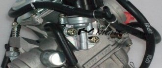
Carburetor diagram for 139qmb
| Carburetor outlet channels. “Fuel injection channels” - used at the moment of opening the throttle valve, that is, they are used as transition channels at the moments of closing/opening the valve |
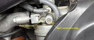
Throttle valve limit screw.
Information from a post on one automobile forum regarding the same screw, but on a car carburetor:
But what about this (quote from the Daewoo Nexia primer): . The initial position of the throttle valve when the accelerator pedal is released is adjusted and fixed with a limit screw at the factory. This damper position provides sufficient air flow in the intake manifold to install the IAC shut-off element in the required discrete position during automatic frequency control. It should be noted that in relation to this engine, the initial position of the throttle valve cannot be considered as the position corresponding to the minimum idle speed. The head of the idle speed limit screw is closed with a cap. Warning It is prohibited to remove the protective cap of the limit screw and make adjustments. Incorrect adjustment may result in damage to the IAC or throttle body. .
| The throttle stop screw is not intended for adjusting idle speed! This screw limits the movement of the damper to prevent it from wearing out/jamming. |
| According to the manual, the standard setting for the idle speed adjustment screw is two turns +\- 1\4 |
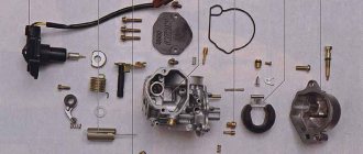
Check all O-rings for damage. Replace if necessary. A poor seal at the seat of the enrichment valve has a very negative effect on the stable operation of the carburetor and, accordingly, the engine.
When cleaning the carburetor, remove the vacuum diaphragm before using purge air or cleaning solvents. This will prevent damage to the diaphragm.
Excellent video with an animated demonstration of the carburetor:
Possible malfunctions of the CVK carburetor
1.The engine is difficult to start
— No spark - Poor compression
2. There is no fuel in the carburetor
-Closed fuel line -Closed fuel filter -Blocked vacuum line -Damaged/broken vacuum line -Clogged inlet needle -Float level set too high
Float level: with this position of the float, the needle should just close the fuel line.
| The carburetor is in an inverted state, the float presses on the needle with its own weight. The measurement was taken from the center of the protruding seam of the float and to the horizontal plane on the carburetor body, photo below. |
| reference points for measuring the position of the float |
It is also worth paying attention to the needle itself and the float. It has a spring-loaded stop, or rather a rod, through which the float tongue presses on the needle
So, when adjusting the carburetor or repairing it, you need to pay attention to this emphasis. It happens that when the equipment is idle for a long time, this spring-loaded rod gets stuck and it does not play on the spring. If this happens, you need to develop it using liquid keys or diesel fuel. If the rod turns sour tightly, it is better to replace the needle.
| Compressed needle stop |
In a strictly horizontal position, the protruding line on the float and the line on the exhaust tract of the carburetor, the spring-loaded stop of the float needle should take the middle position.
3. Too much fuel for the engine
-Dirty air filter -Air leak in the intake manifold -Faulty enrichment valve ( jammed or bad seal at its seat)
) -The air channel in the carburetor is blocked
4. Air/fuel mixture too rich or too pale
-The enrichment valve is faulty ( jammed or bad seal at its seating location)
) -Idle screw too tight -Float needle stuck or dirty -Float height too high or too low -Carburetor air passage blocked -Air filter dirty -Carburetor or manifold leaking air
5. Engine does not accelerate
-Bad spark -Air mixture screw too tight -Accelerator pump faulty
6. Almost does not respond to the throttle
-Weak spark/poor ignition -Blocked fuel line -Blocked fuel filter -Bad fuel -Water in fuel -Air leak in carburetor or manifold -Faulty enrichment valve -Fuel movement in carburetor is difficult -Vacuum choke stuck -Damaged vacuum diaphragm -Dirt in carburetor
DIY scooter turn relay
From time to time, questions arise with turn signal relays when LED lamps are installed in the turn signals on a motorcycle, and not only on motorcycles, but also on cars, or when the turn signals themselves are replaced entirely with LED ones. Standard relays, as a rule, refuse to work with such light bulbs because the load is too small. It (the relay) perceives the LED lamp as a broken wire and begins to switch faster than usual. Under normal conditions, this is convenient: the relay began to “click” faster than usual, which means that some light bulb has burned out. But for someone who has consciously replaced incandescent bulbs with LEDs, this is the beginning of a headache. Just a few years ago, electronic turn signal relays for LEDs cost about 500 rubles, which is not at all humane. Then I just needed a relay for the LEDs. After scouring the Internet, I found an article about converting a conventional automotive three-pin electronic turn signal relay into a relay for LEDs. I did everything as described, everything worked, I forgot. But lately, apparently, spring is taking its toll, and the question of relays for LEDs has often come up. Anyone interested, please see cat. Compared to what it was a few years ago. the situation seems to have improved. So, literally today, while corresponding here with one of the forum members, who ordered himself a special turn signal relay for LEDs, I found out that the prices for these relays have dropped. According to this forum member, he ordered himself a relay for 170 rubles. Today, I bought a regular car relay at a car store for the same 170 rubles. I suppose that I could find it cheaper, because... this store is far from the cheapest, but I live in a small town, there are few stores, I stopped by another store, they ran out of relays. And I don’t see the point in going somewhere else because of winning 10-20 rubles.
So, let's move on to the remake. To understand what exactly and how we will redo it, here is a relay diagram:
In the diagram, the pin that needs to be disconnected is crossed out.
Now let's move on to practical implementation. I bought a relay like this:
I would like to draw the attention of those who have a standard two-contact relay. On the old Yamaha R1-Z it was just like this
Don't be scared! There is simply no mass wire there.
Relay connection. The relay has 3 outputs: 39 - ground, always connected. 49 - constant +, connects when the ignition is turned on 49a - signal, goes to the remote control, the turn switch and the emergency lights. To connect, you need to determine which wire is which in the standard wiring. If there is a diagram, good; if not, you need a test lamp. First, let's find the mass. One terminal of the test lamp is on the + battery, with the other we try the wires in the connector. The turn switch and hazard lights must be turned off. Where the lamp lights up, that is the mass output. We connect the wire of the probe lamp to any ground contact and try the wires in the connector, while not forgetting to turn on the ignition. But the lamp can light up in both wires (depending on the connection diagram of the control lamp in the device), so we turn on any turn signal or emergency lights. The wire where the probe lit up is the desired +. The remaining wire is the signal wire. You can check it by shorting the + and signal wires with the turn signals or emergency lights on. The turns should light up. If anyone is afraid, you can connect these 2 wires with a probe lamp, then the turn signals will light up, but dimly, and the probe is only slightly worse than when connected to the battery. And all because we turned on the turn signals in series with the probe.
Further, there are already possible options for who exactly will connect the relay to the standard connector. In such cases, I usually do not cut off the connector itself, but make an adapter from wires and terminals.
If anyone still doesn’t understand something, ask, I’ll try to answer. But I'll be away for the weekend, so there may be a delay in replies.
Source
Interchangeability of switches
Separately, it is worth talking about the interchangeability of switches for scooters, since this issue worries many people who use these vehicles. Fortunately, this question brings only positive emotions, since in most cases the switches on different scooter models are interchangeable. This means that if one switch is damaged, you won't have to look everywhere for the exact same one, because you can use any other one that you can find.
Naturally, we cannot say that absolutely all switches are interchangeable; there are some points that you should pay attention to. First of all, this is the presence or absence of a Hall sensor in the circuit - in some scooter models it replaces the ignition coil, and, accordingly, the switch that interacts with the Hall sensor will not be suitable as a replacement for the switch that interacted with the ignition coil
There are other restrictions - for example, you will not be able to use a commutator that is used for an engine with a different number of cylinders. Luckily, scooters almost always use single cylinder engines, but this is still something to keep an eye on.
Replacing the scooter turn relay
The standard turn signal relay for scooters of the most common models consists of:
- holding winding;
- attracting winding;
- capacitor;
- resistor;
- plastic case;
- fastenings and wiring.
The principle of operation of the relay and its care
Like the design of the relay itself, the principle of its operation is as simple as possible. The current entering the node passes through both relay windings and serves to charge the capacitor. When the charge capacitor reaches a certain power, the current flowing through the attracting winding will become strong enough to operate the relay. In this case, the holding and attracting windings are disconnected. After this, the capacitor is discharged using the holding winding to a certain level. The relay turns off and the entire operating cycle repeats again. The purpose of the resistor in this circuit is to discharge the capacitor when the power supply to the scooter is turned off (which means it comes to a complete stop).
The turn relay in operation is almost no different from other electrical equipment. This means that caring for it requires the same conditions and manipulations as all electric scooter devices, namely:
- protecting the device from moisture penetration into the housing;
- preventing chemicals or other aggressive substances from entering the wires and connections of this unit;
- shocks, compression, pressure or other mechanical impacts on the device body, which may result in damage or damage to it;
- preventing overloads in the electrical power supply circuits of the scooter and, as a result, short circuits, which invariably leads to failure of this lighting system unit.
In addition, the relay, like other parts and systems of the scooter, must be kept clean, that is, periodically wiped and treated with special products to remove dirt, dust and deposits of oily substances.
Types of damage, disassembly procedure and replacement of the turn relay
The main indicators of partial or complete failure of the turn relay are:
- unstable or more frequent switching on (blinking) of turn signal lights;
- inability to turn on the turns (the light does not respond to the switch);
- The turn signal lights turn on, but do not blink (they just light up and go out only after they are turned off).
If such symptoms appear when the lamps and wiring are fully operational, then it’s time to replace the turn signal relay. And to do this, naturally, it is necessary to disassemble that part of the scooter that interferes with free access to this unit. In different scooter models, the location of the relay can vary from the area under the front plastic to the rear of the vehicle. Depending on this, the front or side parts of the scooter are disassembled.
When disassembling the scooter to replace the relay, you must:
- Place the scooter on a flat surface on the center stand;
- determine the location of the relay on this scooter, guided by the operating instructions;
- unscrew and remove the plastic at the location of the relay;
- release the part from the fastening clamps (in most cases they are rubber);
- remove the part;
- carefully disconnect the plastic connector of the relay (it can be either with or without additional wiring);
- connect the new relay to the on-board network;
- install the part in place and secure it with clamps;
- Reinstall the removed plastic and securely fasten it with the fixing bolts.
The procedure for replacing the turn relay is one of the simplest types of scooter repair, which even an inexperienced novice driver-owner can handle.
However, when replacing the turn relay, one should not neglect the general rules for all types of scooter repairs, namely:
- before starting disassembly, you need to thoroughly clean, wash and dry the scooter (especially hard-to-reach places and places most exposed to dirt);
- carry out repairs in a clean room and only using clean tools (keys, screwdrivers, containers);
- You should stock up on a container (or several) for storing small parts (bolts, nuts, O-rings).
After installing the new relay, you need to check its functionality by driving the scooter for some distance.
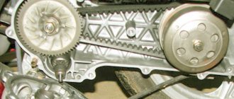
Engine Features
The official manufacturer of the 139QMB scooter engine is Hongling Corporation, which equips motorcycles not only of its own brand, but also of other brands with this engine.
The corporation sells power units to other manufacturers. The motor itself is very recognizable: the design features of the 139QMB engine and its markings on the left side of the crankcase immediately make it clear what kind of heart beats the scooter.
The motor has no flaws, does not require special treatment and calmly tolerates minor negligence and negligence. The manufacturer provides a guarantee for its products that covers the first 5 thousand kilometers. This mileage is enough for the new 139QMB 4t scooter engine to fully run in and grind in all elements and components of the systems.
The total service life of the engine is about 20 thousand kilometers, with the exception of 5 thousand running-in at an average driving speed of 90 km/h. The technical characteristics of the 139QMB engine are not bad: its power is enough for a two-seater full-size scooter.
How to replace the voltage regulator relay on a scooter
The voltage regulator on a scooter is an important element to ensure the normal operation of electrical equipment. It is he who is responsible for supplying a voltage of a certain nominal value to electricity consumers in the scooter’s on-board system.
Replacing the voltage regulator relay on a scooter may be necessary if the device fails.
One such example is stopping the supply of charging current to the battery contacts while the generator is working properly.
Let's take a step-by-step look at how to properly replace a scooter's voltage regulator on your own:
- We install the scooter on the central support.
- We determine the location of the voltage regulator relay in the device of your scooter model. If you do not have such information, use the manual for your device.
- Depending on the location of the part, the necessary elements of the scooter lining are dismantled. In some cases, you will need to remove the front plastic, sometimes the regulator is located in the back, and often its place is in the area under the “toilet”. For the latter case, it is enough to remove the seat area along with the seat to find the treasured regulator. Typically, this is a small aluminum device, slightly larger than a matchbox, with cooling fins to dissipate heat. The electrical connector goes to it.
- So, we have determined where the voltage regulator is located on the scooter; all that remains is to carefully replace it. Its body is usually attached to the frame or other components of the scooter using a bolt, rarely a self-tapping screw. The bolt can be an open-end wrench, often a hex wrench. We unscrew the relay from its seat, without losing the fasteners.
- Disconnect the connector chip.
- The new voltage regulator must fully correspond to the markings of the stock version, have a similar pinout and connector. When purchasing a part in a store, be sure to indicate the model of your scooter. If the seller has an idea about the product he is selling, choosing the necessary spare part will not be difficult for him. We connect the relay regulator to a standard connector.
- We install the part in its normal place, securing it with a fastener.
- We assemble the remaining parts of the scooter, for example, the plastic lining, in the reverse order of disassembly.
Carburetor cleaning
Before adjusting the carburetor on a 2t or 4t scooter, you should thoroughly clean the system mechanisms.
To do this, you can use one of two methods. In the first case, the carburetor is washed with gasoline and purged with a compressor. The equipment must have a nozzle in the form of a pointed tip. If you don’t have suitable equipment at hand, you can purchase a special liquid for flushing the carburetor. With its help, all channels, parts and elements can be easily cleaned. The liquid is in a can. Therefore, it is supplied inside under pressure. This principle facilitates thorough purging of even narrow channels.
There is no need to dry internal systems after flushing. They simply reassemble the systems in reverse order. Next you can make settings.
Work principles
The variety of turn relays is quite large, but they are all divided into two main types:
- classical electromagnetic-thermal relays;
- electronic relays.
Electromagnetic-thermal relays are considered obsolete and can now only be found on very old cars, for example, classic Zhiguli cars. This type of relay consists of a core with a copper winding. There are two contact groups in the upper part of the core, and metal anchors in the sides. The structure is placed in a metal case, in the lower part of which contacts for connecting to the network are output.
When the turn switch is turned on, the network is closed - the lamp does not light. Then one of the anchors, under the influence of the nichrome string in the core, straightens and closes the contacts. After this, the current begins to flow in a bypass circuit, and the lamp lights up at full power. The click of the turn signals is ensured by the impact of a metal armature on the contacts.
An electronic relay consists of two main parts: a classic electromagnetic relay and an electronic key that ensures the frequency of operation of the relay. In a relay of this type, the operating principle of the nichrome string, which ensures the closure of the contacts, is assigned to a separate circuit board (key). Otherwise, the operation scheme is similar: the flowing current closes the contacts, after which the indicator lamps and the light on the dashboard light up. Interruption of the current leads to lowering of the armature and opening of the contacts - the indicator lamps go out. A characteristic click is also provided by the impact of the armature on the contacts.
So we will make an electronic turn signal relay for a scooter using a diagram (you can download it).
The circuit itself consists of three parts - a powerful field-effect transistor, a resistor and a flashing LED. All parts are not in short supply and inexpensive; they can be bought at any radio store or radio market.
Download the turn signal relay diagram
The best results are obtained with a flashing red LED. Everything is soldered directly using hinged mounting, output to output.
This is what the turn signal relay looks like on a scooter
The approximate cost of this scooter turn regulator is $2 with a time investment of 1 hour. Of course, if you don’t even know where the relay is on the scooter, then you don’t need to start soldering something right away - first read our articles on repairing and tuning scooters with your own hands. Happy DIY tuning!
Electrics and electrical equipment of a scooter
Dedicated to all owners of Chinese scooters...
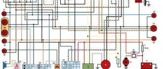
To begin with, I would like to present a wiring diagram for a Chinese scooter.
Since all Chinese scooters are very similar, like Siamese twins, their electrical circuits are practically no different.
The diagram was found on the Internet and is, in my opinion, one of the most successful, since it shows the color of the connecting conductors. This greatly simplifies the diagram and makes it more comfortable to read.
(Click on the image to enlarge. The image will open in a new window).
It is worth noting that in the electrical circuit of a scooter, just like in any electronic circuit, there is a common wire. On a scooter, the common wire is the minus (—). In the diagram, the common wire is shown in green. If you look more closely, you will notice that it is connected to all the electrical equipment of the scooter: headlight (16), turn relay (24), instrument panel backlight lamp (15), indicator lamps (20, 36, 22, 17), tachometer (18 ), fuel level sensor (14), horn (31), tail light/brake light (13), start relay (10) and other devices.
First, let's go over the main elements of the Chinese scooter circuit.
Egnition lock.
Ignition switch (12) or “Main switch”. The ignition switch is nothing more than a regular multi-position switch. Even though the ignition switch has 3 positions, the electrical circuit uses only 2.
When the key is in the first position, the red and black wires are connected. In this case, the voltage from the battery enters the electric circuit of the scooter, the scooter is ready to start. The fuel level indicator, tachometer, sound signal, turn relay, and ignition circuit are also ready for operation. They are supplied with power from the battery.
If the ignition switch malfunctions, it can be safely replaced with some kind of switch like a toggle switch. The toggle switch must be powerful enough, because the entire electrical circuit of the scooter is, in fact, switched through the ignition switch. Of course, you can do without a toggle switch if you limit yourself to short-circuiting the red and black wires, as the heroes of Hollywood action films once did
In the other two positions, the black and white wire from the CDI ignition module (1) is shorted to the housing (common wire). In this case, engine operation is blocked. In some scooter models, to block the engine, there is an engine stop button (27), which, like the ignition switch, connects the white-black and green (common, body) wire.
Generator.
The generator (4) produces alternating electric current to power all current consumers and charge the battery (6).
There are 5 wires coming from the generator. One of them is connected to a common wire (frame). The alternating voltage is removed from the white wire and supplied to the relay regulator for subsequent straightening and stabilization. The yellow wire removes voltage, which is used to power the low/high beam lamp, which is installed in the front fairing of the scooter.
Also in the design of the generator there is a so-called hall sensor. It is not electrically connected to the generator and there are 2 wires coming from it: white-green and red-black. The hall sensor is connected to the CDI ignition module (1).
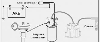
Relay regulator.
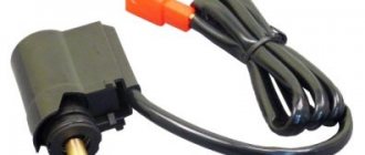
Regulator relay (5). People may call it a “stabilizer”, “transistor”, “regulator”, “voltage regulator” or simply “relay”. All these definitions refer to one piece of hardware. This is what the relay regulator looks like.
The relay regulator on Chinese scooters is installed in the front part under a plastic fairing. The relay-regulator itself is attached to the metal base of the scooter in order to reduce the heating of the relay radiator during operation. This is what the relay regulator looks like on a scooter.
In the operation of a scooter, the relay regulator plays a very important role. The task of the relay regulator is to convert the alternating voltage from the generator into direct voltage and limit it to 13.5 - 14.8 volts. This is the voltage required to charge the battery.
The diagram and photo show that there are 4 wires coming from the relay-regulator. Green is the common wire. We have already talked about it. Red is the output of positive DC voltage 13.5 -14.8 volts.
The regulator receives alternating voltage from the generator through the white wire to the relay. Also connected to the regulator is a yellow wire coming from the generator. It supplies the regulator with alternating voltage from the generator. Due to the electronic circuit of the regulator, the voltage on this wire is converted into a pulsating one, and is supplied to powerful current consumers - the low and high beam lamps, as well as the dashboard backlight lamps (there may be several of them).
Four-stroke engine intake systems - alternatives to poppet valves[edit | edit code]
The development of the four-stroke intake system followed the path of eliminating, as far as possible, progressively moving valve mechanism components. While the DOHC design comes as close as possible to this goal, the poppet valve itself remains the limiting factor. The poppet valve works well, but has obvious disadvantages. In addition to being a reciprocating mass, it also represents a significant obstruction to the incoming mixture, thereby generating unwanted turbulence and drag that prevents the cylinder from filling. Much effort has been made in the development of modern designs to compensate for these shortcomings, but the main problems still remain. In recent years, countless attempts have been made to replace the poppet valve with an alternative valve system, with the rotating cross valve design being the most promising. It is a hollow cylinder mounted across the cylinder head in a special chamber. The valve cylinder rotates at half the engine speed, with a slot in its wall aligned with the intake or exhaust port at the appropriate point in the engine cycle. Thus, the valve mechanism is actuated similarly to the disc valve of two-stroke engines and ensures free flow of gas into the combustion chamber. Norton tried such valves on its sports engines in the early 1950s, but, faced with sealing problems, subsequently returned to poppet valves.
Along with the spool valve and the Aspin valve, the rotary cross valve was rejected mainly due to its inherent sealing problems, and the poppet valve was strong enough to discourage manufacturers from further research. However, the rotary valve concept has not been forgotten, and there is already a four-stroke engine that does not use poppet valves. It is a rotating cylinder with windows. The cylinder is driven from the crankshaft using a gear transmission; the rotational speed of the cylinder is half the speed of the crankshaft.
A significant feature of this engine is that the piston moves progressively in the same cylinder, that is, sealing is provided by a standard piston and its rings. It is essentially a combination of the rotary valve designs mentioned above and the ducting system used on a two-stroke engine.
Wiring work
The large black wire connects: 2 yellow, green and red, where direct current flows. Red goes into the ignition switch, from which by turning the key you can close the system and make it work. On the reverse side, the harness goes to the console, where it is connected to the switches. If voltage has been lost, then you should look at the operation of this harness - does the voltage go out from the ignition switch into this black harness.
The second line serves to power the battery (black-red), pulse from the magnetic sensor (blue-white) and has ground (green). There is a lot of voltage going to the battery, and therefore you can only touch the wires with the engine off.
If the question arises about how to connect the wiring on an Alpha moped if there are problems with this line, then you should pay attention to the armored wire - the large black wire that goes to the spark plug from the ignition coil. And a rather dangerous symptom allows you to suspect a break in the black-yellow wire: if the moped does not stall, but will work until the gas runs out
This wire turns yellow in the middle and goes to the ignition coil.
Ignition circuit components
The ignition system is an important element in the operation of the entire scooter. The formation of a spark and a precisely calculated impulse that ignites the fuel depend on it.
The scooter ignition circuit includes many components that are responsible for a specific job.
CDI ignition module
The first item in the list is the CDI module. This abbreviation stands for Capacitor Discharge Ignition - ignition from a capacitor discharge.
The switch module is made in a non-separable box, so if it fails, it is replaced with a new one. 5 wires are connected to it, distributed throughout the entire ignition circuit of the scooter.
The block is hidden inside the scooter, so getting to it is not easy. The plastic covers will have to be completely dismantled.
Ignition coil
The purpose of this component is a fast pulse of high voltage voltage based on a signal from the switch. It goes directly to the spark plug, where it is converted into a spark.
The coil is located on the right side of the Chinese scooter and is attached to its supporting structure. It is easy to recognize - it is made in the form of a plastic barrel. On the reverse side there is a thick wire connected. It is he who transfers the discharge according to the circuit from the transformer to the spark plug.
To protect against dirt and dust, the coil is placed in a rubber cover.
Spark plug
Its function is simple - to form a spark and ignite the mixture inside the cylinder. The scooter uses an A7TC spark plug.
Its position is hidden from view, but experienced owners know where to look for it. Having passed along the high-voltage wire, we reach the engine block and the spark plug cap.
The rubber seal protects the contact from accidental electrical breakdown. Remove with a little effort towards you. Do not pull the wire too hard - the cap may come off.
The spark plug is unscrewed with a socket wrench. After removal, you need to inspect the color of the contacts and their condition. An indicator of good engine performance is a brown tint without traces of soot. Deviation from the norm indicates a malfunction of the carburetor.
Starter
The device is used to make it easier to start a scooter engine, without using a kick pedal. The starter is located in the middle part of the moped, near the engine. To open it, you need to remove the decorative plastic.
The starter is connected through the starting relay, which is located on the scooter frame.
Fuel gauge and indicator
The sensor measures the amount of gasoline in the tank and signals the need to refuel. It is located in the tank itself and is connected by three wires.
The indicator is directly connected to the sensor. Both are powered by stabilized current from the rectifier. If problems are observed in the operation of the indicator, you should check the connection to the circuit.
Voltage is supplied only when the ignition switch is turned on.
Turns relay
The breaker is used to control the turn lights. When the button is closed, the relay produces current pulses with a frequency of 1 Hz.
The block is located under the instrument panel. To change the relay you need to remove the plastic protection.
Switching the circuit is not difficult. When turning right, voltage flows through the blue wire, which is responsible for the corresponding lamps. The left position of the switch shorts the gray bus to the orange one.
Duplicate lamps on the instrument panel are connected in parallel to the turns circuit lines. They signal that the lamps are on on a specific side of the scooter.
Sound signal
The purpose of the sound horn is clear to everyone. On the scooter it is located near the limiter relay.
The signal is powered by direct current through the ignition switch and is activated by a button on the handlebars of the moped. The component is non-separable, so if it fails, it is completely replaced.