Let's try to revive the VM Galaxy scooter; its electrical circuit is typical for devices of this class (the only differences are in the Suzuki Sepia).
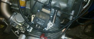
Remove the plastic and look for the elements of the ignition system. The switch is not difficult to find: it is a small plastic box with a connector that accepts 5 or 6 wires with insulation of different colors. It is even easier to detect the ignition coil: a high-voltage wire leads to it from the spark plug (it is thicker than others). The electromagnetic sensor and generator are located in the engine, but their functionality can be checked without disassembling it.
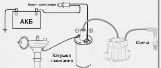
Imagine how an electrical system works. The voltage comes from the generator to the switch and accumulates in the capacitor. Based on a signal from the electromagnetic sensor, the capacitor is instantly discharged to the ignition coil. In it, the voltage of this impulse increases to several thousand volts and is supplied to the spark plug through a high-voltage wire, through the spark plug cap. A wire runs from the switch or sensor to the ignition switch - it is used to turn off the engine: when the switch is turned off, the wire is shorted to ground. Your task is to check all these circuits.
Arm yourself with a digital multimeter and set it to resistance measurement mode. Make sure the motor is in electrical contact with the scooter frame. Then determine the purpose of the wires that go to the switch connector. Start with the ground wire (usually green) - there should be zero resistance between it and the frame. Two wires approach the ignition coil: one is connected to ground, the other goes to the switch. Look at the color of the “switch” (you will find it in the switch connector).
Disassemble the scooter beak. Remove the ignition switch from the protective cap.
Select from among the wires those that are suitable for it. The one that matches the color of one of the wires on the switch connector is the “jamming” wire. It remains to determine the purpose of two wires - from the generator supply coil and from the electromagnetic sensor. Black with a red stripe, usually from the pickup, the other from the supply coil. To make sure that you have not made a mistake, measure the resistance between them and the “ground”: the sensor resistance is 2-3 times greater than that of the high-voltage winding of the generator.
The electrical circuit of the Suzuki Sepia differs from the one described: it has a switch and an ignition coil combined into one housing. Here you can only check the wires going to it and the resistance of the generator winding, which is also a sensor.
It is more convenient and reliable to check nodes if you measure the resistance at the terminals of the wires going to the switch. At the same time, check the wiring: it happens that the electrical circuit is broken in it. If the multimeter shows that the resistance of one of them is equal to infinity, then, “moving” along it, you will find a break.
Start the “movement” with the spark plug cap. Having looked into it, make sure that the spring installed on the contact is not lost, and the cap itself is put on the spark plug with noticeable force (if the fastening is unreliable, the engine will run intermittently). This part must be equipped with a rubber o-ring - otherwise in wet weather the spark will “run away” to ground.
It is easier to check the secondary winding at the same time as inspecting the high-voltage wire and spark plug cap. Remove the cap from the spark plug and check the resistance between the terminal that fits onto the spark plug and ground. We got about 7.5 Ohms. Now disconnect the cap from the wire and determine the resistance between the wire conductor and the ground - it should be about 2.5 kOhms. Therefore, the resistance of the noise suppression resistor is 5 kOhm. The wire resistance should be zero.
If you need to replace a high-voltage wire, look only for the one with a metal core. Automotive high-resistance, having a wire core with carbon filler, is unsuitable here!
Now it’s the turn of the ignition coil. Here you need a digital voltmeter - the resistance of the primary winding is insignificant, and a dial gauge will not give accurate data. Check the resistance between the wire that goes to the coil and ground. There is a peculiarity here. If you short-circuit the probes of a digital ohmmeter, its reading is usually greater than zero. Remember exactly how much and subtract this value from the reading when checking the coil. The difference should be equal to 0.2-0.3 Ohm - this is the resistance of the primary winding. Is the ignition coil ok? Go ahead.
The next stage is the motor “stub” circuit. Connect a multimeter to the wire running from the switch block to the ignition switch. Turn the ignition key: in the “off” position the device should show zero, in the “start” position - “infinity”.
It remains to check the condition of the electromagnetic sensor and the supply winding of the generator. Find a black wire with a red stripe in the switch connector, measure its resistance relative to ground with a multimeter: it should be about 500 Ohms. This is a sensor. The resistance of the supply winding wire (in our case it is blue with a white stripe) is 150-200 Ohms. If the value is noticeably less, there may be an internal short circuit in the supply coil. In this case, it will no longer provide sufficient voltage for a spark. If you have any doubts about the functionality of the part, contact a workshop: special equipment will be required to dismantle and diagnose the generator. If you try to disassemble the generator on your own, you may break it.
If all of the above elements of the ignition system are in order, and the ground wires are securely connected to ground, but there is still no spark, then the switch is faulty. It is impossible to check it in a garage - you will have to contact a technical service or, in order not to fool yourself, buy a new switch. When you look for the reason for the “death” of the replaced one, do not listen to those who say that the accident occurred because you drove without a battery. It's a bullshit! The power supply systems, which include the battery and ignition, are completely independent on scooters.
And now about the easiest way to destroy electrical equipment. Sooner or later, something needs to be done on an “old” scooter. Remember, if you work with electric welding, even if you just need to “grab” something or “put an end to it”, be sure to disconnect the switch and voltage stabilizer - otherwise you will ruin them. During welding, secure the welding machine ground as close to the welding site as possible. Please note that the power units of most scooters are attached to the frame through silent blocks - they do not allow current to pass through. This means that the current will flow through the “mass” wires. And this is like death: in a few seconds the welding current will turn the wires into a lump of “reinforced” molten plastic.
The purpose of the coil is to increase the voltage coming from the capacitor to 18 kV. This voltage is needed to form a spark at the spark plug. The coil consists of two windings on a core made of special iron (transformer). The windings have a common core. Attaches to the scooter frame using a bolt and hole 4.
The primary winding has fewer turns around the core. It is connected to the commutator at one end through terminal 1. The second end of the primary winding has a common terminal at the ignition coil, with terminal 2 with the second winding.
The secondary winding has several times more turns around the core. It is connected to the spark plug at one end through connection 3, and the second end, like the first winding, has a common terminal and is connected to ground.
How to check a scooter's ignition coil.
We will check the coil of the Honling scooter. The engine is four-stroke 50 cc. Remove the coil and disconnect the wires. The high-voltage wire is unscrewed from the coil like a regular bolt. The first check is visual, for physical damage to the housing crack. Serviceability of connecting terminals. All parts must be dry and clean.
The next check is the main one with which we will check the serviceability of the windings. In this case, we will measure the resistance of each winding. This will ensure the integrity of the windings. For this we need a resistance measuring device (tester).
Checking the primary winding
We connect the device to terminals 1 and 2. We set the device switch to 200 Ohm. We look at the device readings. The resistance of the first winding is 1.3 Ohms.
Checking the secondary winding
This time we connect the device to terminals 2 and 3. We set the switch to 20 kOhm. The resistance of the secondary winding is 2.77 kOhm, as shown by the device.
If the device does not show the resistance of one of the windings. This means the ignition coil is faulty. Replaces with a new one.
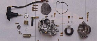
Adjusting the Suzuki Sepia carburetor
Before the procedure, you should remember that when changing parts such as a cylinder, filters, muffler, the old carburetor settings will be invalid and you will have to make adjustments again. It is also extremely important to adjust the jets when the engine is already warm. The process is carried out as follows:
- Adjustment of needle and venturi tube size at 1/3 gas;
- Adjusting idle speed and mixture quality.
Setting up the carburetor in a Suzuki Sepia scooter
The Japanese scooter Suzuki Sepia is considered a fairly popular model in Russia and other countries, in particular due to its attractive appearance and simple design of the engine and other parts. But problems with this scooter are quite common and are caused by malfunctions of such components as the CPG, carburetor and variator. It is important to carefully monitor their condition to prevent damage. As for the carburetor, the Mikuni carburetor is used here; the Suzuki Sepia is ideal for this carburetor model, which is also used on other equipment. In particular, you can see a similar model on the no less famous Suzuki Adress scooter. The carburetor is characterized by its simple design, good quality and the ability to quickly adjust. But judging by the frequent problems of owners, it will be extremely difficult to adjust the carburetor for optimal operation of the scooter; the entire procedure will have to be carried out exactly according to the specified rules. If you are the owner of a Suzuki Sepia, get ready to clean the carburetor frequently, because its location is so inconvenient that the carburetor becomes clogged with dust very often. Below is a carburetor setting option.
ATTENTION. Update your browser! Our site does not work correctly with IE 8 and older versions.
Guys, today I accidentally found this ignition on the Internet, it’s too similar to Simon’s. There are also 4 coils and that’s it! Who tried this? They put a high-voltage coil with a built-in switch on the original ignition (a coil from the same scooter, Suzuki sepia)
Only you forgot to say that for this kit you will need a commutator and a high-voltage coil, which is not in the photo, and this is at least another 800 rubles, plus you will have to worry about installing an induction sensor, since the original ignition system did not have one and the high-voltage coil is combined in one housing with the commutator . You can install all this, I installed it on a Jeepix like this, but this will require tools and straight hands. This is not just a renovation, but a modernization.
Hello. I just had a problem with the ignition. Motor Simon 2. Here are the photos
In the first photo on the right is the original stator (all the wires are already without insulation), to the left of the Suzuki Sepia. The second and third photos on the right are Sepia, on the left is the original. According to the seat, it fits like a native one.
They wrote on the forum - they installed it without modifications and everything works.
By wire. It is clearly visible that both stators have 4 wires. On the original stator, the yellow-white wire (I tied it in a knot) was also in the bundle, but cut off. So only three wires came out of the wiring harness: black and red is + to the coil, blue is ground to the coil, white and red is the output to the voltage regulator. Exactly the same color on the stator and should be connected from Sepia. My motor is still disassembled. I’ll definitely write how it works.
Needle adjustment
The peculiarity of this carburetor is the absence of a jet for the quality of the mixture; its adjustment here occurs by raising or lowering the locking ring on the needle. If you notice that the mixture is too lean, you will have to install the ring higher by 1 or 2 grooves; accordingly, the mixture will be rich when installing the same ring on the 4th or 5th step. The center position on the 3rd groove indicates the standard throttle needle setting. If configured correctly, the scooter will have good traction, speed and consume fuel according to the specified characteristics.
Why do you need to regulate?
During the adjustment process, the scooter carburetor needle is adjusted, the position of which affects the proportions of the air-fuel mixture, as well as a number of other adjustments.
Adjusting the scooter carburetor needle is done during the adjustment process
Each tuning operation has a different effect on engine operation and fuel preparation:
- adjusting the idle speed ensures stable operation of a running engine when the transmission is turned off;
- changing the quality of the air-gasoline mixture using a special screw allows you to deplete or enrich it;
- adjusting the position of the carburetor needle affects the change in the quality of the fuel mixture;
- Ensuring a stable level of gasoline inside the float chamber avoids flooding of spark plugs.
Setting the air screw
The carburetor also has a jet responsible for the amount of air located under the cover. The jet is located in the air channel, so when you tighten the screw, the throttle rises and the air flow increases. At the same time, the engine speed increases.
Configuration is carried out as follows:
- completely tighten the screw and unscrew it 4-5 turns;
- the engine should start to stall;
- gradually tighten the screw until the speed increases to maximum;
- upon reaching maximum speed, you can unscrew the screw ¼ turn;
- adjust the idle speed screw for optimal speed.
Checking power on the switch
We connect the battery. Turn the ignition key. We measure the incoming voltage at the switch connector. 12 V should be supplied to the red wire from the battery through the fuses and the ignition switch. We set the device to V-20 V. We connect one probe to the green wire, the second to the c/h wire.
If there is 12 V, then on dio 34 we immediately check the voltage on the pink wire - it should be 9 V. This means that the electrical circuit from the battery to the switch is working.
Some older Japanese Suzuki and Yamaha models do not have a switch. The ignition coil operates directly from the pulse generator. Therefore, there is no need to check the voltage from the battery, but you only need to check the operation of the generator and rectifier (according to the diagram).
How to set up and adjust the carburetor on a scooter
Having bought a motorcycle, scooter or other motorized equipment, owners have to become familiar with the operation and adjustment of their main components. One of the important elements of a two-stroke or four-stroke power unit is the carburetor, which is responsible for supplying fuel to the combustion chamber and mixing gasoline with air in the required ratio. Many people do not know how to adjust the carburetor on a scooter using the adjusting screw. This need arises if the device does not start well, shows increased appetite, or the tachometer needle indicates unstable speed.
Checking the Pulse Generator
We measure the resistance of the Hall sensor coil at the switch connector. We set the device to 2 kOhm. We connect one probe to the green wire, and the second to the s/w. Should be 114 ohms. This means the wiring and Hall sensor are working properly.
If the circuit does not show resistance, then this indicates a break in the coil or electrical wiring from the pulse generator to the switch.
Next, we check the functionality of the entire pulse generator along with the mechanical part. Switch the device to 2 mA, leaving the probes in place.
We pull the leg of the kickstar. From the Hall sensor, for one rotation of the magneto, one pulse with a small current is supplied to the commutator. The meter should show approximately 0.6 mA. This means that all elements of the pulse generator are working properly and the reason for the lack of spark is not in the Hall sensor.
If the device does not show current, then you need to remove the air cooling casing. Look at the gap in the mechanical part of the generator, between the magneto and the Hall sensor. Check to see if the crankshaft bearings are loose or if the wire from the sensor is broken.
Idle speed: settings features
Adjusting the Suzuki Sepia carburetor is impossible without using the idle speed. It regulates the number of revolutions, where when the screw is tightened, the speed indicator increases and the wheel spins independently without the throttle. When you unscrew the idle screw, the scooter will start only when you add more revolutions with the throttle. It is advisable to adjust this jet last, that is, first adjust the quality of the mixture, the needle in the throttle valve, and, if necessary, the air screw, and then adjust the idle speed.
Purpose and principle of operation of the carburetor
The carburetor is an important component of an internal combustion engine, responsible for preparing the air-fuel mixture and supplying it to the working cylinder in the required ratio. A scooter engine with an unadjusted carburetor cannot function properly. The stability of speed, the power developed by the engine, gasoline consumption, response to turning the throttle, as well as ease of starting in the cold season depend on the correct settings of the engine power supply.
An important component of an internal combustion engine is the carburetor.
This unit is responsible for preparing the air-gasoline mixture, the concentration of the components of which affects the nature of the operation of the power plant. The standard ratio is 1:15. Leaning the mixture to a ratio of 1:13 ensures stable engine operation at idle. Sometimes it also becomes necessary to enrich the mixture by maintaining a ratio of 1:17.
Knowing the structure of the carburetor and knowing how to adjust it, you can ensure stable operation of the engine on two-stroke and four-stroke scooters.
Thanks to a properly configured carburetor, easy and quick starting of the vehicle engine is ensured, as well as stable operation of the engine, regardless of the ambient temperature. Any carburetor is equipped with jets with calibrated holes, a float chamber, a needle that regulates the cross-section of the fuel channel, as well as special adjusting screws.
The adjustment process involves specially rotating the screw in a clockwise direction or in the opposite direction, which causes, respectively, the enrichment or depletion of the working mixture. Adjustment measures are carried out on a warmed-up engine. In this case, the carburetor unit must first be thoroughly washed and cleared of blockages.
The principle of operation of ignition in a 4-stroke scooter engine
Modern scooters are equipped with contactless systems. They are considered the most reliable and easy to use, do not require complex connections, and provide a constant good spark on time. However, the setting is still important; even the presence of a spark does not always allow the fuel mixture to ignite, since its power also plays a role.
The main reasons for the operation of the ignition system are quite simple: its task is to create a spark to detonate the fuel mixture. If this does not happen, you need to carefully examine each node and find out why the spark disappeared.
- In order to check whether there is a spark at all, you need to unscrew the spark plug and apply it to the engine ground; this can be done using metal objects that are not covered with paint. You cannot hold it with your hand: if there is a spark, it can give you an electric shock, and the discharge reaches 40,000 volts, which the coil creates.
Broken ignition is the cause of engine failure
An incorrectly configured or faulty ignition often causes engine failure. It would be wrong to immediately climb into the cylinder and examine the insides of the scooter, especially since this will not solve the problem. Before touching the ignition system, you need to check for other reasons why the scooter may not work.
Design and principle of operation of the CDI ignition system coil
The coil of the CDI ignition system is a classic two-winding high-voltage transformer. The work of which is based on the effect of magnetic inductance.
Inside the ignition coil there is a cylindrical or rectangular core on top of which a large amount of very thin copper wire is wound in a strictly defined order, representing the secondary winding. On top of the secondary winding, through a layer of insulation, a thicker copper wire is wound, representing the primary winding.
Both windings are connected at their ends to each other and have one common terminal on the housing in the form of a ground terminal (green). The second ends of each winding have separate outputs on the housing in the form of a power terminal and a central contact of the high-voltage wire.
For greater clarity, let's break the case apart and see what's inside.
How to set the ignition on a scooter
With minimal experience, but good theoretical knowledge, you can set the ignition yourself. To do this, you just need to strictly follow the instructions below.
The most important part of tuning is to find the correct position for the timing sprocket to sit. In order to find it, they use special marks that are applied at the factory during engine assembly. The desired mark looks like the letter "T". In this position, the piston is at dead center. This is the extreme position after which the piston will return back. You need to rotate the rotor until the protrusion on the crankcase and the letter “T” coincide. This can be done using your hands or a kick starter. An electric starter does not need to be used.
If the piston has only moved down minimally, turn it further until the marks line up. It's not always possible to get the right position the first time. After they match, you need to study the other marks: they are located on the timing star. Usually these are three points or holes that are located on the outside of the star. They form a triangular shape if you connect them visually. Notice that one point is larger than the others. After adjusting the ignition, it should be on top, and the other two marks should remain opposite each other. They must stand horizontally.
If the ignition is contactless, it is adjusted as follows. In order for the engine to run smoothly and correctly, you need to adjust the ignition of the mixture at the right moment. To do this, after all the tags are installed in the right places, you need to understand how the contactless principle works in general.
A special feature of the BZS is the presence of special sensors, a switch, and two types of ignition coil winding. When the sensor is closed using a rotor equipped with a magnet, a pulse is generated that enters the commutator, it pumps up the current coming from the generator and directs it to the primary winding of the coil. After this, the charge enters the secondary winding, where a high voltage is generated, with the help of which a spark appears, used to detonate the gasoline mixture. Adjusting the ignition is the alignment of the marks on the crankcase and the star. Usually you have to remove the valve cover.
After this you need to do the following:
- Labels are set in the manner described above.
- In order to set the ignition angle, you can release the stator mount and adjust it in accordance with the technical requirements of your vehicle.
- Make sure that the marks or holes are in the correct position.
ATTENTION. Update your browser! Our site does not work correctly with IE 8 and older versions.
I need your help.
For those who are familiar with measuring instruments, please measure the resistance of the generator winding, Simon, f200 will do. To do this, you need to remove the terminals from the commutator/voltage coil and connect a multimeter to them in ohmmeter mode. / I'm trying to fix an engine with a weak spark.
Thanks in advance!
You're burning Sanya!
I realized what I wrote
everything that generates electricity is a GENERATOR; a GENERATOR can have any number of windings. In our case, there are two windings, and there are four coils in the generator
One winding for powering the switch, the other winding for the on-board network (charging the battery) And the diagram there is drawn very correctly! And the topic is not really about that at all; no one said anything.
Well, Sanya, you drew the same thing wrong. It was not for nothing that I said earlier that I am aware of the recusal, namely the recusal. To confirm, I can take a detailed photo of the stator with f200, you can clearly see that one edge is on the ground, then there is an outlet and the second edge is a full outlet. Not for the sake of argument, for the sake of truth.
Ps. Let me describe the situation again.
An engine with an unstable start, does not start from the first push, with an excellent starter and a good battery, it spins vigorously but does not catch right away, it can start ten times and then stop starting altogether. The spark is barely noticeable, reducing the gap does not have much effect, cold hot doesn’t matter. When it starts, it works mediocrely, at the slightest over-enrichment, misfires and shooting into the pipe begin. With a moderate mixture it reaches maximum and works confidently, but everything is not constant, you can turn it off and the next time you start everything will be wrong or it won’t start at all. The power supply system is fully operational!
The sepia stator did not fit, most likely it will fit the Simon, but it did not fit the F200, it is almost 5mm larger in diameter.
What is advance ignition
The quality of the mixture supplied to the engine cylinder determines the behavior of the scooter in cold weather, as well as how high the wear of the cylinder itself will be. For example, with a rich mixture, the engine starts better, but carbon deposits form; with a lean mixture, the cylinder quickly wears out and traction is lost.
In order to facilitate the process of starting the engine, you can set the ignition to advance, this will make it easier to start the engine regardless of the weather outside, slightly increase engine power, and significantly increase traction. The peculiarities of such settings are that a charge is formed in the spark plug before the piston reaches the dead center. This makes it easier to start the engine and increases engine power. However, it is worth remembering that cylinder wear may increase.
The procedure is carried out in approximately the same way as a regular ignition adjustment, but has its own nuances. To do this, all the same actions are carried out, only the tags are not completely connected. The discrepancy should be approximately half a centimeter. This is enough to get the desired effect.
How to set the lead angle (video)
About adjusting the ignition of a 4t scooter
Knowing how to set up the ignition of a 4T scooter on your own, you can save time and money, since you will not need to contact a motorcycle repair shop. The procedure is simple, even if you have no experience it takes a little time, but you will need to be patient. Regardless of the type of ignition, an important role is played by how the marks are set.
Correct adjustment is a guarantee of stable and smooth engine operation even in cold weather conditions. Often, in used vehicles, the ignition is broken: this can happen for various reasons, ranging from elementary shaking when driving to improper handling of the equipment. In order for the scooter not to let you down and for you to be able to start it whenever you want, you will need to learn how to carry out this procedure yourself. To do this, you will need to have several keys that allow you to remove the valve cover if the engine is four-stroke.
Setting up the Vision scooter ignition system
If the ignition is knocked out, this may be the reason the scooter does not work. Restoring it is not difficult if you understand how it is done.
Advice: before starting work, carefully check and clean the carburetor: this may be the reason. Adjust the quality of the mixture. In addition, it doesn't hurt to check the spark plugs.
You need to start adjusting by setting the timing belt in the desired position. As a rule, there are marks on it for this purpose; they are set at the factory. The cylinder must be installed at dead center. The mark may be indicated by the letter T or another symbol. Now make sure that the mark installed on the rotor matches the mark found on the magneto. To do this, you need to gently press the kickstarter. The rotor can also be turned using your hands, but this is more difficult.
There are also marks on the timing star in the form of holes or dots; they must be set so that the largest hole is on top and located exactly in the center. The remaining points should be below and located horizontally opposite each other. Setting the ignition advance makes sense if you want to increase the engine's power a little and make it start easily. The adjustment will help make the spark plug produce a spark earlier than the standard time. That is, a spark will appear even before the piston reaches the dead center. In cold weather, a moped configured in this way will start better.
In order to configure the scooter in this way, you will need to repeat the procedure described above. However, there is a difference: the marks should not coincide clearly, and not reach each other by about 0.5 cm. The main difficulty lies in connecting the marks.
Scooter switch - scooter electronic ignition device
Scooter engine - device Scooter carburetor - device, setup Scooter crankshaft Scooter gearbox - device Scooter clutch - device, setup Scooter variator - device Scooter chain drive device Scooter electrics Scooter brake system Switch - electronic ignition of the scooter Scooter speed limiters
See also Diagram of a simple switch, without electronic advance. Scooter ignition advance
Operating principle and device of electronic ignition / switch. An excellent article about this is taken from the site ntscooters.moy.su
Over the years of developing cars and motorcycles, we came to the conclusion that this scooter system should be as reliable as possible, because scooters are intended for carefree people
Therefore, Japanese scooters do not have cam ignition systems like IZ motorcycles and scoops (old mopeds). Even the oldest Hondas use an electric sensor. But more on that later. After all, not all scooters have it. For example, Suzuki Sepia has a rather clever shaft position control system. Therefore, you will not find diagrams of this switch on the Internet. It is quite complex in its internal architecture. I'll tell you about this later. Now I want to classify and break down the existing ignition systems on Japanese, Chinese, Korean and European scooters.
Depending on the type of engine, several systems are distinguished. 2-stroke Chinese mopeds have a system exactly copied from Sepia. But in terms of reliability it is simply terrible! The switches in it are on fire, only the noise is there! Personally, they brought me about 5 such mopeds with this symptom. Maybe a defective batch, but still take note. I’ll immediately note a significant difference between this system and Honda’s and Yamaha’s: the absence of an ignition sensor (also known as an induction sensor). I will describe the entire internal process later.
Japanese mopeds from Honda have several types of switches. I won’t write about tuning, we’ll limit ourselves to the standard. 18E engines have the simplest and most reliable ignition system of all scooters. In its design, it strongly resembles the ignition of the Carpathian mopeds, if it does not copy it exactly, which is quite likely. It differs from narrow ignition by the presence of an ignition sensor (induction) and a separate coil on the generator, which is in no way connected with the rest of the scooter’s electronics. This has advantages: if the generator is overloaded with lighting fixtures and other things, the ignition system will not fail. But it also has one significant drawback. A large amplitude voltage comes out of this coil on the generator, about 160-600 volts (at different speeds), which can be felt if water gets lightly on the contacts of the switch. Also, this coil can, under certain conditions, simply short out in turns (due to the amplitude), and then your scooter will stop, and you won’t even understand what’s wrong. You will spend a very long time looking for the cause of a weak or completely absent spark. Also, tuning switches for this system are complex in design. After all, you know that they non-linearly change the ignition timing at different speeds. And here there is also current and voltage jumping. Therefore, it is necessary to create a stabilization system, and a serious one at that. This is not the case with stock switches, but if you want to understand the nuances at low levels, then you need to know this.
For some reason I have a hunch that the tuning switches do not have microcircuits, and the advance is done simply by an RC timing chain, but this is just a guess.
I will also write about the ignition system of the 34 Honda engine. Things are a little different here. There is also an induction ignition sensor, it is identical to the sensor from the 18th engine. But the switch is powered not from a separate ignition coil, but from a common battery charging circuit. That is, in other words, from the battery. Also the regulator is a little different. More current is supplied to the battery here so that it is not discharged by the switch.
There was a case with me: I was driving from the dacha, due to inexperience in assembling the engine, the wires coming from the generator were hanging at the bottom of the engine. I somehow didn't notice them. It was already starting to get dark when I ran over some rock. The headlight immediately turned off. I thought the lamp had burned out. But switching the headlight mode did not correct the situation: there was no light. I stopped and checked the taillight. It didn't burn either. I thought that the wiring had broken or the regulator had run out. Since I wasn’t particularly strong in electronics at that time, I gave up and went home. There were 4 kilometers left to the house. I arrived safely, but in the morning I discovered that the wires coming from the generator were simply broken. Except for the ignition sensor wire. The battery was in the trash. It turns out I was driving it! Of course, in some cases this can be seen as a plus!
Now for some science. This system was developed in order to completely free the scooter from water dependence, increase the reliability of the generator and get rid of “extra wires”. The design of the switch is more complex due to the lower supply voltage. But now we can easily install elements sensitive to energy surges. Therefore, it is not advisable to ride such scooters without a battery. It seems to smooth out ripples and stabilize the mains voltage.
Yamaha and Suzuki scooters, as well as Chinese scooters, have similar ignition systems.
Now I’ll tell you a little about how the switch works. With the generator, I think everything is clear. It produces an alternating voltage of a given amplitude at certain crankshaft speeds. In order for an arc to occur, it is necessary to know the dielectric properties of air. The breakdown voltage per 1 mm is approximately 3 thousand volts. Also, for reliable ignition, you need to create a spark of a certain duration. The main energy converter for igniting fuel on a scooter is the ignition bobbin or coil. It turns 100 - 400 volts into approximately 6000 - 20000 volts. However, the current also decreases proportionally. Those who have ever touched high-voltage wires know what it is.
Well, okay, the reel is not very complicated and practically eternal... Although, if we are not talking about a Sepia switch. It contains both the bobbin and the switch itself - in one.
The task of the switch is to apply an impulse to the reel at a certain point in time, of a certain duration and amplitude. What I will write next may not be clear to many, but radio technicians will definitely understand.
We will consider only thyristor or so-called. capacitor ignition systems. They are used in all the scooters described here... The commutator has a capacitor that stores energy. As soon as the moment of sparking arrives, this capacitor will short-circuit to the primary winding of the ignition coil. And this process is controlled by a thyristor. Therefore, the system is called thyristor or capacitor.
The stock commutator for the 18E engine on Honda and many Chinese cars works on this principle. In order for the amplitude to reach its operating value at the bobbin output, the capacitor must be charged with a capacity of 0.5 -1 µF and an amplitude of about 200 volts. And as you may have guessed, the switch has to be powered with high voltage in any case. Therefore, switches with 34 motors contain a pulse voltage converter. It makes 200-300 volts from 12 volts. And another plus is that at any speed the spark will be the same in power, which increases stability at idle and makes starting easier. This is the difference between the commutator of the 18th motor and the 34th. I have not seen such switches on Chinese mopeds, because... in production they are much more expensive than the previous ones. It is quite possible that they use them there too. I would also like to say something about limiters. They are performed in different ways, most often using a timing chain. And if you change the condenser, the limiter will move to one side or the other on the scale. There are also other types of limiters.
It is worth mentioning separately the switch from Suzuki Sepia; I repeat that the same is used by the Chinese, which our magazine does not recommend. That is, with a pipe curved in the letter S and a two-stroke engine. In them, the basic principle of operation is no different from the switch with the 18th motor. However, the shaft position control system is different. Exactly what it is, one can only guess. Personally, I have not disassembled any such switch. The Japanese deliberately made this knot uniform and mysterious so that no one would want to copy it, but there were still craftsmen in China.
Material used from www.ntscooters.moy.su.
Scooter engine - device Scooter carburetor - device, setup Scooter crankshaft Scooter gearbox - device Scooter clutch - device, setup Scooter variator - device Scooter chain drive device Scooter electrics Scooter brake system Switch - electronic ignition of the scooter Scooter speed limiters
Tweet
#1 Alexander
31 May 2010 16:40
What could it be? I changed the spark plug, the carburetor, and the filter and the scooter goes 500m and stalls, waits for a minute and then goes 500m and the same thing happens again. Help me please!!!!
#2 Vyacheslav
01 June 2010 10:16
Alexander! blow out the gasoline pipe! Wash the carburetor in an ultra sound bath! Maybe he’ll go that way!
#3 Vyacheslav
01 June 2010 10:18
I have a suzuki sepia, I also drive about 100 meters and it stalls. I stop and it starts AGAIN. I blew out the gas line and washed the carburetor in an ultra-sonic bath! and drives like a darling! TRY TO DO THE TOO!!!!
#4 Igor
10 June 2010 18:07
Hello
#5 Igor
10 June 2010 18:08
I start my scooter, turn it off, don’t turn it off, tell me
#6 Evgeniy Konstantinovich
13 June 2010 15:42
Chinese scooter, 2-cylinder, chain, ТХМ50A-1, does not start, excellent spark, compression 8.6; quality needle 2 turns, quantity 2.5 turns, spark plug is new, still wet from the first kick. It looks like the ignition timing is wrong, how can I adjust it? Thank you in advance.
#7 dock
15 June 2010 23:25
Igor, check the ignition switch, maybe it’s disconnected. But my headlight burns at full incandescence, before you jump on bumps.
#8 Igor
16 June 2010 10:30
I CHECKED NO WAY I WILL START IT WITHOUT KEYS
#9 Alexander
22 June 2010 15:23
In general, this is the case. The scooter stalled. 4t. It was like this - 2 weeks ago we put it on the steering wheel and seat to secure the silencer. We drove later, everything was fine. A little bit of oil dripped through the filter. A week ago we went with a friend to drive, drove 5-6 km. There is a straight road, for drag racing. We decided to make the most of the scooter. We squeezed out 80 km per hour. Well, we finally decided I went on to drive. I got behind the wheel and when I started accelerating along the same straight line, at 79 km per hour there was a shooting, but it was quiet. the scooter suddenly began to slow down and the tachometer needle went crazy, it would drop to 4,000, then it would fly up to 9,500 (although there is a limiter at 9,000)))). doesn’t catch on. With the kick it’s also 0. We waited for another 5 minutes. Then suddenly it started up with the kick. I let it run for 1 minute and turned it off. I thought let it rest. Okay, we calmed down, we think we’ll drive again. A friend got behind the wheel. Let’s go... at 40 km per hour there were gunshots again, but louder than before. And they had bluish smoke. By the way, when I started it, there was no smoke. It actually fired 3 times and died. After that, it finally didn’t want to start... it went away a quarter of the way to the house and decided to try their luck again and start one. Once on the 5th hit on the kick it started up. The rpm was immediately at 6000, but as soon as I let off the gas a little, it stalled. And after that it never started up. What could it be? They thought after the revolutions something was poured on the “head” with oil. but we traveled for 2-3 weeks after that. I cleaned the spark plug from carbon deposits. The needle in the carburetor is in place.
#10 DenisSochi
23 June 2010 18:21
on the Chinese YH 50 QT Fortune the spark is gone, tell me where to find the switch, the working switch is interrupted from the sensor, with the magneto when starting from the button it gives 1.5 volts. When calling, what should be the indicators??????????
#11 Nikolai
23 June 2010 19:37
Which switch is similar to SYM jet 50
#12 Nikolai
27 June 2010 12:18
I was driving and the wire fell off the spark plug! Now it won’t start at all. tell me what to do
#13 Fedor
02 July 2010 15:49
Tell me, is it possible to do without a switch in the ignition system?
#14 Alex
08 July 2010 10:57
It is forbidden!!!
#15 Fedor
12 July 2010 09:42
In short, we need a Chinese car with only a broken ignition from 2007, call 89607930300, I think we’ll agree on the price!!!!
#16 Gennady
19 July 2010 22:55
changed the oil, turned the starter to drain the oil from the pump, now it won’t start, no spark, how to ring the wiring of an eagle 150 china
#17 Vyacheslav Zubkov
23 July 2010 07:55
Guys, I have a Yamaha Jog Cool Style. One day something got stuck on me and the bolts were stuck to the frame! the spark is gone! Tell me what could have burned???
#18 Tiger
24 July 2010 22:51
Where is the switch on the Chinese Honling Summer? I saw somewhere that it was under the seat on the frame, but there was only a coil there and nowhere else
#19 Igor
25 July 2010 20:22
I bought a new battery after 2-3 days of driving, the battery dies, I charged it and drove again for 2-3 days, tell me who knows what to do for communication
#20 Sanya
25 July 2010 20:59
And the battery is probably not good for 7ah, but it will be more!?!?
Home Scooter device Scooter switch - scooter electronic ignition device