Installation of the cylinder-piston group
It is not advisable to remove the gearbox cover until the sealant has dried; there is no need to rush in this matter.
It’s better not to rush things and install the cylinder while the sealant dries. Add some motor oil:
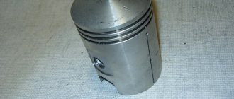
To improve lubrication, it is advisable to drill holes in the piston bosses. But you don’t have to drill - it depends on your desire.
Install the piston pin retaining ring into the boss. Before installation, it is advisable to bend the locking ring a little and be sure to check how it fits after installation:
We heat the piston with a hairdryer and, using a mandrel, drive the finger into the piston so that it comes out no more than 5-6mm.
We look for an arrow-shaped mark on the bottom of the piston.
We orient the piston with the arrow towards the exhaust port of the cylinder (“towards the exhaust”), put the piston on the connecting rod, hammer in the piston pin and install the second retaining ring.
We insert the rings into the cylinder and measure the gap between the locks with a feeler gauge:
To improve the wearability of the rings and reduce noise from engine operation, it is advisable to chamfer the edges of the rings. If hunting gets too much trouble: place the ring on a flat surface and use a file to slightly round the edges.
We put the rings on the piston, fill the piston with the rings with oil, install a gasket under the cylinder (preferably with sealant), tighten the rings with a clamp. We cut the clamp out of tin and from the same tin we bend the bracket with which we will fix it.
After the rings go into the cylinder, unfasten the clamp, lower the cylinder and screw it to the crankcase.
We turn the crankshaft several times and if the piston moves in the cylinder easily and without grinding, lower it down a little, pour a little engine oil into the cylinder, install a new gasket on the cylinder and screw the head on.
We install the additional crankshaft support bearing in its place, place the required number of adjusting washers on top and secure it with a retaining ring. The adjusting washers must ensure axial play of the crankshaft within 0.1 mm.
Before installation, sealed bearings must be opened! The usual 304 goes here.
On the other side of the crankshaft we install a flange with a main oil seal.
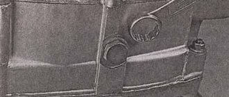
Pay attention to the oil channel through which oil flows to the right main bearing of the crankshaft. According to the good old collective farm tradition, this channel is sealed with sealant and the lubrication of the bearing stops
To avoid this trouble, place the flange dry without sealant and everything will be fine.
After the sealant has dried, you can begin adjusting and assembling the gearbox and replacing the clutch basket.
Numbers of bearings and oil seals for the Izh-Planet motorcycle engine 2, 3, 4 and fifth model.
Maintenance
The owner can independently perform some maintenance procedures:
- check the motorcycle generator if the battery loses charge;
- set the gap between the breaker contacts;
- adjust the quality of the sound signal.
The need to inspect and adjust the wiring arises if:
- the motorcycle moves in the rain for a long time, as this causes oxidation of the contacts;
- a motorcyclist rides in an area with a lot of vegetation that damages wiring;
- The driver rides in snow in winter, which can stick to electrical wiring parts and damage them.
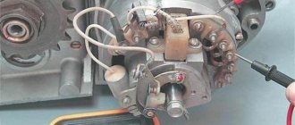
Self-check of the Planet 5 motorcycle generator in case of loss of charge
The cause of loss of charge in the IZH Planet 5 battery is most often a breakdown of the generator.
To check it yourself you need:
- multimeter device;
- straight screwdriver.
Step-by-step instruction
The following steps must be followed:
- Disconnect the wires from the battery and remove the generator cover.
- Disconnect the top 5 wires from the generator, first unscrewing their fastenings. In order not to mix up the wires during assembly, it is worth marking them.
- Measure the winding resistance using a multimeter in ohmmeter mode. To do this, you need to touch the body with one probe, and the other should be connected in turn to the 3 wires of the winding. There should be no short circuits, as indicated by the inscription on the multimeter screen.
- Test the resistance between the stator contacts: you need to touch them one by one with the multimeter probes. The value on the screen should be 8 ohms.
The presence of a short circuit in the 3rd stage or a discrepancy in the indicators in the 4th will indicate problems with the generator.
Photo gallery: stages of checking the IZH Planet 5 generator in case of loss of charge in pictures
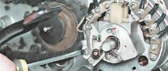
How to correctly set the gap between the contacts of the breaker?
In order to set the gap between the breaker contacts, you will need:
- straight screwdriver;
- wrench 10;
- candle key;
- probe 0.4 mm thick (+/– 0.05 mm).
Next, you need to follow the steps sequentially:
- Place the motorcycle on a stand and place the gearbox in neutral.
- Remove the right crankcase cover and unscrew the spark plug.
- Using a 10mm wrench, grab the generator rotor mounting bolt and turn the crankshaft to a position where the contacts are as far apart as possible.
- Loosen the screw securing the contact.
- Place the probe between the contacts and adjust the tightening of the eccentric screw until the probe passes the contacts with little resistance.
- Tighten the contact fixing screw.
Photo gallery: adjusting the gap between the breaker contacts
Troubleshooting the audio signal and improving signal quality
Poor sound signal quality is mainly caused by improper adjustment.
The following tools will be needed for setup:
- wrench 7;
- a simple screwdriver.
Step-by-step instruction
To adjust, do the following:
- Loosen the locknut with a wrench.
- Turn on the ignition.
- Press the button to turn on the sound signal.
- Adjust the sound by rotating the adjusting screw.
- When the desired result is achieved, tighten the locknut.
Electrical circuits of the ignition systems of the IZH Jupiter 5 motorcycle
1 - parking light lamp - A 12-4; 2 - high beam - low beam headlight - A 12-45:40; 3 - indicator lamp for generator operation - A 12-1; 4, 5 — speedometer scale illumination lamps — AMN 12-3; 6, 16, 17, 20, 23, 30 — lamps for the direction indicators of the motorcycle and side trailer; 7 - combination switch (right switch); 8 — brake light switch for the front wheel brake; 9 - breaker; 10 — spark plug; 11 — ignition coil; 12 - generator; 13 — rectifier-voltage regulator BPV14-10; 14 — brake light switch for the wheel brake; 15, 19 — side trailer clearance lamps — A 12-5; 18 — brake light lamp for side trailer — A 12-21-3; 21 — motorcycle brake light lamp — A 12-21-3; 22 — motorcycle rear marker lamp — A 12-5; 24 - battery; 25 - fuse; 26 — neutral lamp switch; 27 — ignition switch; 28 — sound signal; 29 — alarm switch (left switch); 31 — turn signal switch; 32 - high beam headlight control lamp - A 12-1; 32 — control lamp “neutral” — A 12-1; 33 - control lamp for direction indicator lights - AMN 12-3; Symbols on the BPV14-10 block (items 12,13): XI - “-” excitation windings; X2 - “-” battery (“ground”); ХЗ - “+” output to the control lamp; X4, X5, X7 - phases of the stator winding of the generator; X8 - “+” of the battery.
Installation of bearings and seals
We install a retaining ring in the left half of the crankcase.
Depending on the model of the main oil seal, we install a spacer sleeve in the mounting hole of the main bearing, or, if the oil seal was initially wide (there are some), we heat the crankcase and, on the inside of the crankcase, place the oil seal until it stops against the retaining ring.
My engine had a regular narrow oil seal, so I put in a bushing.
Using a mandrel, install the main oil seal into the preheated crankcase.
Quickly, before the crankcase cools down, place the oil guide washer on the oil seal. The oil guide washer has a saucer-shaped profile. We place it on the oil seal so that the concave side faces us, and the curved side faces the clutch basket.
While the crankcase has not cooled down, we press the outer race of the main bearing into it using a mandrel.
If you are going to replace the main bearings with new ones, don’t be lazy: find a sheet of iron 7-8 mm thick, cut a wedge in it for the connecting rod, pass the sheet of iron between the cheeks of the crankshaft and use a mandrel to drive the main bearing onto the axle.
This way you will protect yourself from damage to the crankshaft. The main bearing has a very high interference and fits into the axle with a very large force. It is not uncommon for people to simply knock out the axle (the axle on the planetary crankshaft is pressed into the cheek) inside the crankshaft, but they were never able to put the bearing on.
Source
Gearbox Izh Planet 5
The Izh Planet 5 gearbox is four-speed, three-shaft with constant mesh spur gears and foot-operated gear shifting. Switching is carried out using a copy shaft, which is located inside the box; the shift fork pins fit into its grooves. The copy shaft rotates from the shift selector, which in turn is connected to the foot lever. The secondary shaft is hollow and fits onto the end of the primary shaft. The main gear sprocket is located on the secondary shaft. The gearbox is located in the same crankcase with the motorcycle engine, together forming a single power unit. The gearbox is lubricated by oil poured into the engine crankcase. The IZH Planet 5 gearbox can be disassembled without removing the engine, however, for complete disassembly and greater convenience, you can remove the engine from the motorcycle frame. Today we will look at disassembling the Izh Planet 5 gearbox step by step.
Final stage
Next, the second and third speed gears are removed from the input shaft, after which the input shaft is dismantled.
To do this, you will need to carefully knock it out using a stopper and a light hammer. The upper and lower forks are removed. Next comes the intermediate shaft assembly
Using a screwdriver or other suitable tool, bend the clamp with the neutral indicator and carefully pull out the worm wheel. On its far side there are adjusting washers that could stick to the crankcase
They need to be collected and stored with the rest of the removed parts. Next is the turn of the copy shaft. Check the edges of the shaped sockets in which the guide forks move. They should not have chips or dents. We unscrew a couple of screws securing the switching mechanism, which is also removed. Now you can replace unusable parts and assemble the Izh-Planet 5 gearbox according to the scheme. The figure below shows: retaining cap (1), bolt (2), crankshaft sprocket (3), double-row chain (4), clutch drum (5), input shaft (6).
Engine IZH Planet!! DETAILED GEARBOX ASSEMBLY: assembly and adjustment of the gearbox. (Ch-2)
Published May 23, 2018
please tell me I have this problem, when you engage first gear it starts to skip, sometimes it catches, sometimes it doesn’t, help me, tell me))
And where does such a specialist live?
Very useful video, thank you)
I actually have a brass washer on the shank of the input shaft, I bought it with this one and left it there
I assembled the box with all the details, eliminated the backlash, etc., by rotating the wheel, the gears were all there, but as soon as I started it, the gears all disappeared. I was barely coasting. what is the reason?? maybe the cart is slipping?
Quite an introductory video, could you tell me why there are no 3rd and 4th gears? When the second switch is turned on, the switch foot does not go higher and does not switch.
He explained everything perfectly! And about the coins, that’s the most important thing.
I also use a grinder to work on worn-out holds, otherwise the speeds go out of whack.
Dmitry, I have an S 62 motor. Can you restore the city of Ternopil?
Tell me, I have Izh Planet 4 when driving in first gear and second gear, why does the box jerk?
Tell me, with Izh plan 5, can I install a gearbox?
Good video, but I have Jupiter 4, and here my friends fitted two planets with spare parts, each shorter, but the engine on each is assembled. After watching your video, I decided to take them on. Everything is simple and easy))) in your video. There is, as they say, what a waste of time. Thank you for your work. Definitely a like.
Tell me why the gearbox rattles on the Izh PC 4 speed, is it all there? especially 2nd gear and 3rd
Please tell me what the problem is, I put everything under the worm shaft like you have, under the plate where the clutch drum is located everything is flush, when switching from 1 to 2 sometimes it doesn’t turn on 2, you have to turn on from 1 to 3, and then the second, and 3 and 4 Everything is fine
Features of electrical equipment
The wiring diagram of IZH Planet 4 is almost completely copied from the Jupiter model that was the first to appear on the factory assembly line.
The only differences are that:
- The Planet family has one working cylinder, and accordingly the ignition system is designed to ensure its operation;
- The IZ Jupiter family, unlike the Planet, has 2 working cylinders; accordingly, the wiring diagram has additional repeating elements.
Headlight
IZH Planet 4 is equipped with more advanced lighting devices:
- Headlight type "European beam" FG137V with glass with an asymmetrical pattern;
- Low beam mode with lamp A12-45 + 40 W;
- Modern direction indicators type 16.3726 (lamp power - 25 W).
Photo of IZH Planet 4 model 1986
Thanks to the modernization of the lighting system, as well as the configuration of the motorcycle:
- battery 6MTS-9;
- high power alternating current generator 100 W,
The illumination of the road in the flow of traffic has significantly improved, and traffic on public roads has become safer. At the same time, the price of the motorcycle did not change significantly, which brought its sales to a new level of popularity.
Contactless ignition system
The motorcycle used a new contactless ignition system, the operating principle of which was based on the following operating algorithm:
- The generator rotor generates pulses when rotating;
- The storage capacitor is charged through diodes (in the diagram below indicated as VI, V5), as well as through a limiting resistor (R1);
- Passing through the diode (V6), the electrical signal from the sensor winding (3) enters the thyristor (V4);
- After it opens, the charged capacitor (C1) transfers the accumulated charge to the ignition coil (primary winding - 4);
- Under its influence, a high voltage pulse is induced in the secondary winding;
- Through the high-voltage wire, the central electrode of the spark plug receives a charge;
- A spark between the electrodes ignites the air-fuel mixture in the motorcycle engine cylinder.
The factory instructions contain the original diagram of the contactless ignition system
The electrical wiring of the IZH Planet 4 motorcycle, due to the peculiarity of the contactless ignition system, has differences in the layout of the main components:
- The electronic unit of the stabilizer and ignition system is placed in a single housing;
- It is equipped with two plug connectors;
- In order to increase reliability, the block is filled with polyurethane foam (non-separable version);
- Its operating parameters are designed to provide a light signal circuit voltage in the range of 11.5 – 14.5 V.
In addition, the use of a 12-volt circuit led to the division of the ignition system into three electrical circuits that differ in voltage levels:
- A high-voltage circuit consisting of an ignition coil, a spark plug, a spark plug tip and a high-voltage wire;
- Storage capacitor charging circuit, consisting of a charging winding, connecting wires with plug connectors, BCS and the primary winding of the ignition coil;
- The sensor circuit, consisting of its winding, connecting wires and plug connectors.
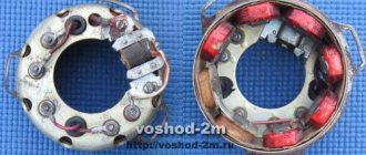
Generator IZH Planet 4
A more advanced generator began to be installed on the new model of the Izhevsk Motor Plant, capable of serving the increased needs of the electrical equipment system, in contrast to the wiring diagram of the IZH Planet 3.
Original factory circuit diagram of the IZH Planet 4 motorcycle generator
Among the design features it is worth highlighting:
- Eight coils placed in the stator slots;
- Serial connection diagram;
- Coating of coil windings with insulating varnish;
- Original fastening to the stator, made using washers and bent petals.
To identify faults with your own hands, you need an ohmmeter or a universal tester, which can be used to measure the resistance of the windings:
- If the values of the measured resistances differ significantly, it is necessary to inspect the generator stator to detect broken winding leads;
- The reason for unstable operation may also be their short circuit. If possible, identified faults are eliminated by soldering.
Assembly
In a carefully washed and prepared for assembly crankcase we place the input shaft, the first gear gear and the follower shaft with pre-selected shims.
We put a fork on the gear-carriage for engaging the second-fourth gear (it is smaller than the gear-carriage for engaging the third-first gear, you can’t go wrong) as shown in the picture. We put the gear on the input shaft and insert the fork pin into the upper groove of the follower shaft.
We put a fork on the gear-carriage for engaging the first-third gear, as shown in the picture, place it on the first gear gear and insert the fork pin into the lower groove of the copy shaft.
We install the fork guides in their places (with grooves towards the clutch basket). By the way, if necessary, the “Planetovskaya” gearbox can be assembled and disassembled without disassembling the clutch basket and without removing the guides. But to do this, during installation you will have to pull the tracing shaft towards you a little, insert the pins of the forks into the grooves and after that, remove the locking bar and push the tracing shaft all the way.
Install the intermediate shaft.
On older engines, the end gear is installed separately. On later ones, it is made integral with the intermediate shaft.
We fill the return spring of the gear shift shaft as shown in the picture.
We check the functionality of the gearshift shaft pawls: compress and unclench them several times
We pay special attention to their working edges: they should be sharp and not licked. And don’t forget to check the spring that compresses the pawls: it must be of the correct shape and ensure the elasticity of the pawls’ movement
We squeeze the pawls and install the gear shift shaft in its place.
We rotate the tracking shaft with the mark on the body towards the gear shift shaft and so as not to miss the mark during installation, we cover the gap between the teeth opposite the mark of the tracking shaft with lithol or paint it. It will be more noticeable this way.
We look for a mark on the sector and when putting the sector on the gear shift shaft, we combine the mark on the sector with the mark on the tracking shaft body: the tooth opposite the sector marks should strictly fit between the teeth opposite the mark of the tracking shaft.
To ensure that our marks do not get lost during installation, we tie together the sector and the copy shaft with ordinary sewing thread.
We put standard thrust washers on the input and follower shafts and insert the guide bushings of the gearbox cover into place.
We degrease the surfaces, apply sealant, lay the gasket, install the cover and tighten the mounting bolts with the maximum possible force. We adjust special washers under the bolts marked with yellow arrows.
After tightening the gearbox cover, we check the axial play of the primary and secondary shafts. Normal: 0.2-0.4mm.
If the play is greater than normal, remove the plate, seat the bearing and adjust the required number of shims under it.
"Sores"
Assembling the Izh Planet 5 box
There are already three sores in the planet gearbox:
- Oil leak from the intermediate shaft plug
- Poor gear engagement in first gear
- Constantly loosening the bolts securing the gearshift shaft stop
I solve the problem with oil leakage very easily and simply: I take out the retaining ring; I remove the intermediate shaft bearing, degrease the plug, retaining ring, mounting hole, then apply sealant to the outer edge of the plug, put it in place and immediately press it with the bearing and voila - the leak is eliminated!
Due to a factory defect, the gear-carriage for engaging the first-third gear does not fully engage the first-gear gear with its cams, but only in a small part, barely catching the gear with its cams, which is why the edges quickly wear out and the first gear begins to knock out.
This moment is clearly visible in the photo. For this particular gear, the hook was no more than a couple of millimeters. It is difficult to cure this “sore”: from the side of the first gear gear, you need to grind the end of the intermediate shaft by 3-4 mm and, using adjusting washers, move the first gear gear to the carriage. I don't see any other way.
During operation, the bolts securing the stop are constantly unscrewed, either due to vibration or something else - they are unscrewed and that’s it, no matter how you tighten them... Even special lock washers do not help. I struggled with this disgrace for a long time using all the traditional methods known to me and came to the conclusion that the best solution to this problem is red thread locker. Feel free to put bolts on it and get rid of this problem once and for all.
Repair
Once the unit has been gutted, you can begin to determine the parts that need to be replaced. As a rule, you have to buy a set of shims, a set of gaskets and sealant. This is the case if there are no more serious damage. Once you have decided on the elements to be replaced, you will need to adjust the worm shaft axis, and after final assembly, the clearance along the axis of the primary, intermediate and secondary shafts.
Adjusting washers are placed on the far ledge of the copy roller; they should be lubricated with a special compound. A support washer is mounted on the near edge, and the shaft is put in place. It should be turned so that the neutral sensor with its protrusion fits into the deepest groove. Then, using a ruler (without the gearbox cover yet) on the plane of the crankcase, measure the gap between the washer and the dipstick. It should be no more than 0.2 mm. Depending on the indicator, regulators are added or removed. If it is impossible to accurately set the gap, it is better to make it smaller.
Detection of faulty parts
To learn how to determine the damage and degree of wear of gearbox gears, consider the classification by which you can make the right decision about repairs. The gear needs to be replaced if:
- there is at least one broken tooth, or the presence of cracks in any part of the tooth caused by plastic deformation of the gear material.
- when the working surface of the gear is chipped by 20 percent or more, when the depth of chipping is 5 percent or more of the tooth thickness.
- if there is corrosion on the working surface of the gears;
- if the contact patch is less than 80 percent of the width of the teeth, and less than 60 percent of the height.
Common faults
The simplest method that will help in some cases. Place the motorcycle on its right side, then remove the kick starter and gear shift lever along with the shaft. Then remove the left crankcase cover, and then remove the clutch basket along with the discs. During operation, the gearbox gears wear out, which causes the meshing of the teeth to deteriorate. This leads to slipping and jerking of the transmission until the second gear fails. Sometimes, when replacing a gear, the problem is not always solved, and lies in the wear of the bearings of the input shaft, which moves to the left over time due to vibrations. To fix the problem, you need to remove the stopper of the input shaft bearing, then move this bearing with light blows of a mallet or with a hammer through the “spacer”, so as to move the shaft to the right. To fix it in this position, you should place washers of appropriate diameter under the bearing. Using the number and thickness of washers, ensure that there is no play in the input shaft, then return the bearing stopper to its place, reassemble the clutch basket and other parts in the reverse order.
Important
When performing these operations, follow the mark in the middle part of the sector. It should coincide with a similar mark on the shaft. The last step is to install the crankcase cover. If the work is carried out correctly, it will sit in its place without problems.
It is necessary to ensure that all rods and shafts coincide with their original mounting sockets. They should rotate freely without creaking or jamming. Use moderate force when tightening the screws as the threads in a soft metal crankcase can easily be stripped. All fasteners are tightened evenly to avoid distortion.