Scooter switch pinout
The scooter switch pinout is a diagram of its connection to the scooter's electrical circuit. There are several types of devices: for example, in Chinese models a DC or AC type switch can be used. They differ from each other not only visually, but also in the principle of energy accumulation for further creation of a spark. DC takes energy directly from the battery, while AC is tied to the generator coil.
Types of scooter switches
Before connecting the switch, it is important to know what type your scooter requires. If you connect the wrong device or do it incorrectly, the switch will immediately fail. The problem is that the part has the same plugs, but you can tell them apart. It's worth starting with the fact that DC is much larger in size.
AC CDI is much more common. It is installed on most Chinese and some Japanese vehicle models. Most often, such a switch is found on those scooters that have a 139QMB or 157QMJ engine.
A slightly different AC switch is installed on “Alpha”, “Delta” mopeds, and other equipment with a 1P39FMB motor. Such a switch operates from a generator coil and requires alternating voltage
DC has a different type of power supply - from a battery, so it has
12V, and if you connect it to a generator, the switch will break. AC is more durable in this regard; most likely, it simply will not work until you connect it correctly.
Photo report: Adjusting valves on a Chinese scooter (139QMB, 157QMJ)
During operation of a four-stroke air-cooled engine (such engines are found on most Chinese scooters and motorcycles), the cylinder head (hereinafter referred to as the cylinder head) can heat up to 260 degrees. This is, of course, not the operating temperature, but this is often the peak temperature.
The valves that are located directly in the cylinder head itself heat up in the same way as the head, with the only difference that the intake valve heats up a little less since it is cooled by the working mixture, and it is ordinary atmospheric air saturated with gasoline vapors, and the exhaust valve heats up much more. Since a flow of exhaust gases passes through the exhaust valve, the temperature can reach 600 degrees.
The problem is that metal parts expand when heated. Valves are no exception: during operation, the valve heats up and becomes a little longer. And when the valve becomes longer, it simply rests against the gas distribution mechanism and opens a little, or rather does not close completely (squeezed), due to which gases under high pressure seeping through leaks melt the working edges of the valve and its seats.
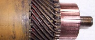
The edges of burnt valves look something like this.
By the way, not only the valves burn out, but also the sockets in which they sit
And this is what the working edges of valves and seats look like after repair.
As you can see, there is little point in regulating something that has already gone bankrupt for a long time. A burnt-out valve will no longer hold compression. And if you find that one of the valves has been jammed, then feel free to remove the head and grind the valves, otherwise there will be no point.
Gaps
Here is the combustion chamber of an ordinary Chinese scooter engine.
During engine operation, the valves heat up to significant levels. And in order to compensate for the expansion coefficient of the valve and the entire timing belt as a whole, there is a small gap between the valve and its opening mechanism. Called thermal.
In our case, the gap that we will adjust is between the valve and the rocker arm adjusting bolt. By tightening the adjusting bolt within the required limits, we can adjust the thermal gap as much as we need.
But do not forget that the gap should not be very large - otherwise the mechanism will work with a shock load and quickly fail. And very small: the valve will heat up, hit the rocker arm and burn out.
Preparation
From the above, you probably realized that the thermal gap exists in order to compensate for the thermal expansion of timing parts. The most important rule follows from this: the thermal gap can only be adjusted on a cold engine. If you start adjusting the heat when it’s hot, you’ll simply increase it since the initial gap will go to expansion. And when the engine cools down, the gap adjusted in this way will double. I hope this is clear.
Pinout
If you have a 4T motor installed on your scooter, the pinout of the switch will depend on what type the scooter requires. For DC it will be as follows:
- The leftmost terminal on top should connect to the generator sensor.
- Ground is connected to the terminal located under it. You can tie the negative wire, for example, to the body of a moped; it is important that the part is metal.
- The upper terminal, located in the center, is connected to the wire leading to the ignition coil drive.
- The one located under it is also connected to the negative wire (ground).
- The wire from the ignition switch is connected to the upper rightmost terminal, which is needed to turn off the engine.
- The power wire is connected to the terminal located under it; it also comes from the ignition switch.
If you have an AC type, the location of the terminals is the same, but they are connected differently:
- We move from left to right, first the top row, then the bottom.
- Here the wire from the generator sensor goes, as in the previous version.
- Next comes the ignition coil wire.
- And at the end there is a “silencer” for the ignition switch.
- The first two terminals are the negative wire, “ground”.
- To the last remaining terminal we connect the power wire from the high-voltage winding of the generator. This point is the main difference when connecting an AC switch from a DC one.
Scooter Honda Dio AF 18 27
The Honda Dio AF 18 has a slightly different switch, made in Japan, which is why the pinout of the scooter is a little unique, and the mounts on the switch are different. It is connected as follows: from left to right, first the upper, then the lower terminals. Location:
- Hall Sensor.
- Ignition coil.
- Weight.
- Ignition lock.
- Power wire from a high voltage coil.
Yamaha Jog Scooter
Several types of generator can be installed on this type of motor vehicle. The most common option has 5 contacts, with wires already coming out of it. Therefore, if you have original wiring, you need to connect as follows:
- Orange should lead to the ignition coil and alternator.
- Black - to the ignition switch.
- Purple – Hall sensor.
- The remaining two wires are connected to the ignition coil.
Chinese scooters
Typically, such vehicles have standard switches, which were described above. The connection diagram depends on whether the AC or DC device is installed on your vehicle. It is worth remembering that different types of switches are not interchangeable.
Signs of a faulty switch: how to check the switch yourself.
Purpose and design features of the switch.
A switch is one of the elements of a car's electrical equipment. His task
– ensuring normal operation of the contactless ignition system. The assembly is fastened in the engine compartment.
The device is reliable, able to withstand severe vibrations and shock loads
This is very important, because the switch housing contains sensitive electronics
At the heart of the VAZ switch
– standard L 497 microcircuit, which controls an “NPN” type transistor.
>Scheme feature
– possibility of programming by the user and setting the required delay coefficient. Starting a cold engine directly depends on the correctness of this indicator.
Thanks to precise settings
, you can speed up the crankshaft rotation speed (while eliminating failures in operation) and guarantee high-quality traction of the power unit.
The main parameters of the switch device include:
Voltage range – from 6 to 16 Volts; operating voltage level – 13.5 Volts; ensuring an uninterrupted spark when the crankshaft rotates in the range from 20 to 7000 rpm; switching current – from 7.5 to 8.5 A.
Signs of a faulty switch.
One of the main symptoms of a faulty switch is loss of spark.
. The engine starts hard and stalls from time to time, causing interruptions in operation.
But don’t rush into replacing it - it’s important to make sure of the reason, because loss of spark can occur for a number of reasons - failure of the Hall sensor, broken timing belt, faulty ignition coil, poor contact in the distributor cap, wiring problems, and so on
Therefore, first of all, a comprehensive diagnosis is necessary. The fastest and most effective way in this case can be a car diagnostic scanner. Most of this type of device is quite easy to use and has an affordable price.
Of those presented on our market, we can recommend paying attention to the multi-brand scanner Scan Tool Pro Black Edition
The advantages of this model include diagnostics of not only the engine, but also other components. Compatible with 99% of new and old cars since 1993, quite easy to use and has wide functionality.
If diagnostics of other nodes does not produce results
, then we can move on to our “hero”. But how to check the switch, since the device has a very complex design?
How to check the switch yourself.
Most car enthusiasts don’t bother with diagnostics and simply install a new unit. This method has its advantages.
Firstly
, there is no need to waste time checking - just install a new part.
Secondly
, you can immediately determine whether this is the reason or not. In fact, there is no need to be afraid of the work, because checking the switch takes a few minutes.
So, to carry out work at home, a test lamp (nominal voltage should be 12 Volts) and a standard set of keys are enough.
With their help, you can verify the presence or absence of pulses, and later make a decision about the serviceability of the device itself.
Algorithm for checking the switch:
To begin work, it is advisable to disconnect the battery so as not to accidentally short-circuit the wiring that you will unscrew.
Using an eight-point wrench, unscrew the nut and remove the wiring from the ignition coil marked “K”. This wire is easy to recognize - it is brownish in color and goes to the terminal labeled one on the switch;
Connect this wire through a control light to terminal “K” on the ignition coil, and then connect the battery;
Turn on the engine starter and observe the lamp's actions. If it blinks, then the switch is working. If the light bulb does not show any signs of life, then the only way out is to replace the device.
If there are doubts about the serviceability of a part, the check should be carried out on a special stand (there is always one at the service station).
In this case, it is possible not only to determine whether the product is working, but also to measure the duration of the pulses.
When the first suspicions appear, you should not immediately change the switch or spend money on a specialist. You are quite capable of doing the job yourself.
Moreover, now you know how to check the switch on the VAZ 2109 and other models of the domestic brand. All that remains is to allocate time and prepare a minimum set of tools. Have a good trip and of course no breakdowns.
Electrics and electrical equipment of a scooter
Dedicated to all owners of Chinese scooters...
To begin with, I would like to present a wiring diagram for a Chinese scooter.
Since all Chinese scooters are very similar, like Siamese twins, their electrical circuits are practically no different.
The diagram was found on the Internet and is, in my opinion, one of the most successful, since it shows the color of the connecting conductors. This greatly simplifies the diagram and makes it more comfortable to read.
(Click on the image to enlarge. The image will open in a new window).
It is worth noting that in the electrical circuit of a scooter, just like in any electronic circuit, there is a common wire . On a scooter, the common wire is the minus ( - ). In the diagram, the common wire is shown in green . If you look more closely, you will notice that it is connected to all the electrical equipment of the scooter: headlight ( 16 ), turn relay ( 24 ), instrument panel backlight lamp ( 15 ), indicator lamps ( 20 , 36 , 22 , 17 ), tachometer ( 18 ), fuel level sensor ( 14 ), horn ( 31 ), tail light/brake light ( 13 ), start relay ( 10 ) and other devices.
First, let's go over the main elements of the Chinese scooter circuit.
Egnition lock.
Ignition switch ( 12 ) or “Main switch”. The ignition switch is nothing more than a regular multi-position switch. Even though the ignition switch has 3 positions, the electrical circuit uses only 2.
When the key is in the first position, the red and black wires are connected. In this case, the voltage from the battery enters the electric circuit of the scooter, the scooter is ready to start. The fuel level indicator, tachometer, sound signal, turn relay, and ignition circuit are also ready for operation. They are supplied with power from the battery.
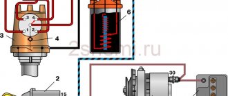
Ignition circuit elements.
One of the most important electrical circuits in a scooter is the ignition circuit. It includes the CDI ignition module ( 1 ), ignition coil ( 2 ), spark plug ( 3 ).
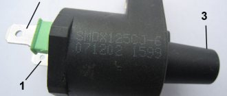
CDI ignition module.
The CDI ignition module ( 1 ) is made in the form of a small box filled with compound. This makes it difficult to disassemble the CDI unit if it malfunctions. Although the modular design of this unit simplifies the process of replacing it.
There are 5 wires connected to the CDI module. The CDI module itself is located in the bottom of the scooter body near the battery compartment and is secured to the frame with a rubber clamp. Access to the CDI block is made difficult by the fact that it is located in the bottom part and is covered with decorative plastic, which has to be completely removed.
Ignition coil.
Ignition coil ( 2 ). The ignition coil itself is located on the right side of the scooter and is mounted on the frame. It is a kind of plastic barrel with two connectors for connection and a high-voltage wire output that goes to the spark plug.
Structurally, the ignition coil is located next to the start relay. To protect against dust, dirt and accidental short circuits, the coil is covered with a rubber cover.
Spark plug.
A7TC spark plug ( 3 ).
The spark plug turned out to be cleverly hidden on the scooter, and it can take quite a long time to find it the first time. But if we “walk” along the high-voltage wire from the ignition coil, the wire will lead us straight to the spark plug cap.
The cap is removed from the candle with a little effort. It is fixed to the spark plug contact with an elastic metal latch.
It is worth noting that the high-voltage wire is connected to the cap without soldering. The insulated stranded wire is simply screwed onto the screw contact built into the cap. Therefore, you should not pull the wire too hard, otherwise you can pull the wire out of the cap. This can be easily fixed, but the wire will have to be shortened by 0.5 - 1 cm.
It's not so easy to get to the spark plug itself. To dismantle it, a socket wrench is required. With its help, the candle is simply unscrewed from its seat.
Starter ( 8 ). The starter is used to start the engine. It is located in the middle part of the scooter next to the engine. It's not easy to get to.
Repair VAZ 2108 2109 21099
Friday, July 10th, 2015
Every owner of the VAZ 2109 should know the ignition circuit. Without knowing this circuit, you will not be able to start the car in case of ignition problems. Moreover, this scheme is elementary simple. The VAZ 2109 is equipped with a contactless ignition system. It consists of the following components: switch, ignition coil, distributor, Hall sensor, high-voltage wires and spark plugs. The task of the ignition system is to provide a timely, cyclic spark to the engine cylinders. Let's take a closer look at how the clamping circuit works.
Ignition circuit for VAZ 2109
ignition of the VAZ 2109: power is supplied to the ignition system through a relay. Until the key is in the ignition position, the relay will not turn on and supply power to the circuit. As soon as the key is turned, the ignition system is energized. +12V power from the battery is supplied to contact B of the ignition coil, the 4th contact of the switch. The Hall sensor powers the switch itself
Please note that the ignition relay is powered through the mounting block, and if there is poor contact in connectors Ш1, Ш8 or for some reason the track oxidizes or burns out, the ignition system will not be powered and the VAZ 2109 will not start. In order for a spark to begin to form, you must crank the engine crankshaft.
Together with it, the camshaft will turn and the Hall sensor will send an impulse to the switch. The commutator, in turn, will connect contact K of the ignition coil to ground, resulting in a spark appearing on the central wire. When the distributor slider connects the central wire and the wire leading to a specific engine cylinder, a spark will jump on the spark plug, igniting the combustible mixture. The engine will start. When it is necessary to turn off the engine, the driver, by turning the key in the ignition switch, turns off the relay, which in turn disassembles the power supply to the system. The switch and ignition coil become de-energized and stop working. The most common malfunctions of the VAZ 2109 ignition system: 1) Failure of the switch. 2) Failure of the Hall sensor. 3) Poor contact of the slider in the distributor. 4) Lack of power supply to the ignition system of the VAZ 2109. Go to Home.
DC CDI switch
One of the most famous switches due to the ease of connection. The most common one has only 4 contacts for the following wires:
Despite its simplicity, there are many switches of this type. It is available with and without a maximum speed limiter, with variable ignition timing, and with additional contacts for a wide variety of needs. In particular, you can “hook” a side stand to some switches, so that when opened, the engine will not spin up to the speed at which the clutch engages. This is done in order to insure the driver against dangerous rash actions.
Signs of a broken switch
During the operation of the car, unpleasant symptoms may occur, indicating a malfunction of the ignition system.
A possible reason for this may be incorrect operation of the switch. Here are the most common symptoms that should suggest a possible breakdown of this device:
- Can't start the engine. There is no spark when the starter is running.
- The engine starts and runs normally at low and medium speeds, but cannot be revved up at high speeds. The engine is not running at full power.
- The car stalls when moving away, although it idles stable.
- The engine starts, but does not run for a long time and immediately stalls.
- The engine begins to operate unstably - “triple”, reaching a certain speed level. When cold it can start quite normally.
- The engine may periodically, without any pattern, stall, then work normally again. The battery discharge indicator lights up. The tachometer needle shows sharp changes in the number of revolutions.
Stock switch for scooter
A stock or original switch is the one that is installed on the vehicle from the factory. Its main advantage over others is that it is already designed for the equipment with which it operates; it is often equipped with a limiter so that the engine does not develop speeds that are dangerous to the life and life of the main bearings, the entire crank mechanism, cylinder-piston groups and other structures and assemblies. The stock commutator is the main source of a well thought out engine's longevity, efficiency and durability. Those who take the risk of replacing a factory switch with a sports (tuning) one are risking a lot. Those who do not fully understand what they intend to do risk even more. Inept installation of such parts and their subsequent use with a conventional engine often lead to a decrease in service life and the death of the engine, sometimes on the same day.
Connection diagram (pinout) of the scooter switch
This article will present connection diagrams (pinouts) for switches, the most popular scooter models in Russia. Also, whenever possible, switches will be opened in order to study their contents in detail.
We kindly ask readers who are well versed in electronics to express in the comments their assessment of the quality, design and tuning capabilities of the switches presented in this article.
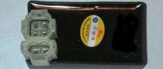
Let's start with the switch model installed on Chinese scooters equipped with a 139QMB engine. Such a switch is of the DC-CDI type, and is quite rare in the “Chinese”.
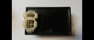
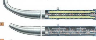
This switch is of the AC CDI type and is installed on the vast majority of “Chinese” vehicles equipped with 139QMB, 157QMJ engines.
This switch after opening.
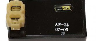
This switch is of the AC CDI type and is installed on Chinese mopeds “Alpha” and “Delta” equipped with a 1P39FMB engine.
“Silencer” - a wire that goes into the ignition switch connector or into the alarm connector; when the ignition is turned off, the wire shorts to ground and the scooter stalls.
The sensor is a wire coming from the magnetic induction sensor of the generator.
160V - the switch is powered by alternating voltage directly from the generator coil (drive).
12V — the switch is powered by constant voltage directly from the battery.
Checking the generator sensor
The magnetic induction sensor is a key element of the ignition system. And if there is any suspicion of a problem with the ignition system, it should also be checked.
Switch the tester to AC measurement mode in the 2V range. With one probe we touch the ground, with the second probe we touch the white-blue or red-yellow wire coming from the sensor and turn the engine with the starter.
- If numbers flash on the screen, there is an impulse
- If the display shows zeros, check the sensor
There is momentum
How to connect a switch on a scooter
09 May 2012, 22:21
thyristor - any 600 volt, more is possible)): 1-t1 2-t2 3-G resistors: p1- 200-220ohm (you can play with the limiter, this one is responsible for maximum speed) p2- 5kOhm p3- 2.5kOhm capacitors: c1 - 50v 10mf (pole) s2 - 22nf s3 - 1mf 400-600 volts any silicon diodes: 1N4001 (for example)
the cost of production does not exceed 100 rubles. I personally assembled 5 such devices, they work right away and do not require any configuration.
PS if anyone needs to disassemble a flooded block, please contact me, I’ll disassemble it and draw a diagram
09 May 2012, 23:06
Here's the diagram you have.
but such schemes (in different variations) are more expensive on mopeds.
They have an ignition timing system (if you’re interested, I’ll tell you in more detail) if you put your circuit instead, it won’t really drive.
And there are DC-CDI units with 12 volt power supply in the same cases and with the same connectors.
Re: Chinese switch circuit diagram
09 May 2012, 23:57
Re: Chinese switch circuit diagram
10 May 2012, 00:05
Re: Chinese switch circuit diagram
10 May 2012, 00:37
Re: Chinese switch circuit diagram
10 May 2012, 00:54
Just don’t copy it, it’s worth a penny. If you want to design it, take the car ignition as a basis. radio magazine 12.2002 page 33
Re: Chinese switch circuit diagram
10 May 2012, 17:03
Re: Chinese switch circuit diagram
10 May 2012, 17:33
Re: Chinese switch circuit diagram
10 May 2012, 17:59
Re: Chinese switch circuit diagram
10 May 2012, 20:39
Re: Chinese switch circuit diagram
10 May 2012, 22:09
Re: Chinese switch circuit diagram
10 May 2012, 22:12
To each his own. &-92&-63о-о3-47 It’s not love that saves, but sex and rock and roll! (c) GZ
repair of foreign-made motor vehicles, welding, turning, drinking works.
Re: Chinese switch circuit diagram
10 May 2012, 22:31
Re: Chinese switch circuit diagram
10 May 2012, 23:31
Re: Chinese switch circuit diagram
11 May 2012, 07:25
Re: Chinese switch circuit diagram
11 May 2012, 09:09
Re: Chinese switch circuit diagram
11 May 2012, 10:31
And I took a programmer from the chipodipo. I received it the other day, checked it yesterday. AVR-ISP500. Otherwise, the old one no longer uses ATmega & ATtiny via LPT. Yes, and you can’t connect it to a laptop-book. Now I’ll finish one thing for the NS, and then I want to install a CDI on it with a DC converter and a variable SPD. Naturally on a microcontroller. Yes, and for CB1 there is a mosk with Atmel already installed, I want to experiment.
And the simplest commutator for a scooter had to be assembled almost in the field using twisted cables. And it didn’t go away, it worked. Not ideal, but it started up, our thyristor was 2U202N, its control was stupid, like three for. off to the heap!
Re: Chinese switch circuit diagram
11 May 2012, 10:54
Re: Chinese switch circuit diagram
12 Jun 2016, 22:02
It works primitively: a transistor is used to start and idle, it opens with a negative impulse from the sensor. upon reaching operating speed (
2200 is adjusted by a variable resistor), the sensor voltage begins to open the thyristor with a positive pulse. The difference from complex circuits is step switching.
Re: Chinese switch circuit diagram
13 Jun 2016, 16:46