Cars admin26.02.2020
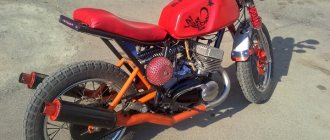
Until now, 6 volt Javas are famous for their reliability, superior even to modern models, but there is only one problem - their generator. Not only is the 6-volt generator very weak in power, but it also provides charging only at fairly high speeds, due to which you have to frequently rev the engine (reducing its service life), especially when traveling at night. Otherwise, the battery is discharged, because when the headlight is on, the generator cannot cope with its duties at speeds below a thousand. Well, one more disadvantage of all 6-volt motorcycles is that 6-volt electric spare parts are disappearing from sale. In this article we will look at one of the options for converting 6 volts to 12.
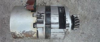
Moreover, we will replace the old Java 6 volt generator not with a 12 volt one from Java, as many do, but we will replace it with a very common and inexpensive (compared to Java) Izhevsk 12 volt generator, from Jupiter, which can be bought in any city. This generator is easy to install on a 6 volt 634 engine, and we will look at how to do this in detail.
I advise you to start upgrading by looking for a blank for the adapter faceplate, and as a blank I advise you to use a used piston from a truck (or rather the bottom of the piston), which can be found in the trash of any vehicle fleet in your city. Well, or look for a workpiece based on the reception of non-ferrous metals. Of course, the faceplate can also be machined from steel, but it is a little more difficult to process, and most importantly, it will be much heavier than aluminum.
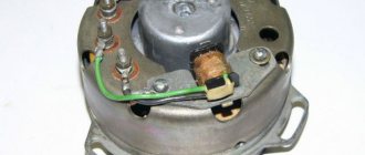
Faceplate for installing the Izhevsk generator (left) and modification of the Izhevsk stator (right). The red arrow shows the stator winding.
Having found the workpiece and reprinted the drawing on the left, you can go to a familiar turner. But don’t forget to take the Izhevsk stator, the side facing the crankshaft will need to be machined, as shown in the drawing. Moreover, grind it so that no more than 1 mm remains to the stator winding, that is, grind off the metal, which is shown in the drawing with a dotted line. Then, relative to the machined end, you will need to machine the seat for the faceplate by 4 mm. And ensure that the washer fits tightly onto the machined stator, but by hand, or by lightly tapping with a hammer. The gap (play) is undesirable here, but hammering the faceplate onto the stator with a sledgehammer is also inappropriate.
And warn the turner so that when fixing the stator into the machine chuck, he ensures that there is no slightest runout of the old bore diameter - this is important. Otherwise, after grooving and installing the stator, the armature will touch its windings (after all, the gap between the armature and the stator is very small).
Drill the holes for attaching the stator to the faceplate and for attaching the faceplate itself to the engine crankcase in place. By the way, an adapter for installing the Jupiter armature on the Java crankshaft cone is not needed. It is enough to slightly modify the Java key with a file, that is, make it lower in height and narrower in width, and the Jupiter armature will fit on the crankshaft of your Java. Just choose a slightly longer bolt to securely tighten the armature to the crankshaft.
When everything is ready and the holes in the faceplate for its fastening are drilled in place, tighten the faceplate to the crankcase, and be sure to use screws that have countersunk heads. Next, you should mark and, having removed the faceplate, drill holes in it to mount the generator, but so that its upper mounts are almost parallel relative to the surface of the earth. Moreover, the rear hole should be drilled slightly lower than the front, because this will make it easier for you to regulate the ignition.
When everything is secured, you will find that a little of the faceplate body will interfere with installing the motor cover in place. This means that this part of the body will need to be sharpened with a grinder. But still, the Jupiter generator (despite the fact that the turner grinds off part of the stator) protrudes out quite a lot. And in order to properly close the lid and tighten it with screws, you will need to cut a hole in it with a diameter of one hundred mm. This needs to be done carefully using a jigsaw in order to cut evenly and save the cut aluminum circle - it will come in handy.
How to find the center of this circle? Its center is located on the first letter A of the JAWA inscription on the engine cover. You will also need to cut out a jumper inside the cover (which is near the generator fastening bolt). Next, into the one hundred millimeter hole you cut, you will need to weld a piece of aluminum pipe with a diameter of one hundred mm and a height of 3 centimeters (30 millimeters) using an argon-arc apparatus.
You will also need to weld two threaded aluminum bosses on top to the pipe walls, in order to then pull the previously cut aluminum circle through a homemade rubber gasket. As I said, the pipe must be aluminum, firstly for normal welding, and secondly so that after cleaning the weld and polishing the welded pipe, the lid looks no worse than the branded one.
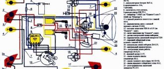
Electrical diagram for connecting Izhevsk electrical parts to Java electrical wiring. 1 - relay-regulator, 2 - generator rotor, 3 - stator windings, 4 - wire to terminal 54 of the ignition switch, x1 - x8 markings of the terminals on the Izhevsk relay-regulator.
Conversion of electrical equipment in Java
Our magazine has repeatedly discussed the shortcomings of the power supply of the YAVA-634 motorcycle, produced before 1985.
At low crankshaft speeds (up to 1800 per minute), the 6-volt generator does not produce energy, and all consumers at this time are powered by the battery. If the lights and headlights are on, the battery is quickly discharged, which, with repeated cycles, leads to its failure. The only measure to avoid this trouble is to maintain medium speed even on bad roads or stops at intersections. It is clear that this causes great inconvenience, especially for residents of rural areas. The currently produced JAVE model “638” uses a 12-volt electrical system (its description and diagram are given in No. 6, 1987), where a more advanced and powerful generator begins to operate already at 1000 rpm.
It is clear that many owners of the old model want to switch to new electrical equipment, but they encounter an obstacle: the main device - the generator - has different connecting and overall dimensions.
A student from the Ural city of Kurgan D. KUZNETSOV overcame this difficulty and successfully converted his car.
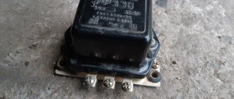
Through the Moscow special base of Rosposyltorg, the address of which is indicated in the instructions attached to the motorcycle, I received a generator (12 V, 210 W), a battery (12 V, 5 Ah) “Trepcha”. The choice is explained by the fact that the domestic battery 6 MTS-9 cannot be placed in the cramped underseat compartment without modification. I also purchased a rectifier, two ignition coils, and a turn signal relay. Since the “native” (model “638”) voltage regulator and warning lamp relay could not be found, I bought a PP330 relay from the Ural motorcycle, taking into account that the difference in generator power between JAVA and Ural is small - 210 and 200 W, respectively .
The essence of the change is as follows.
Mechanical part . We make transition flanges (Fig. 1) and cones (Fig. 2) from steel of any grade. When marking the flange, we use the generator stator as a template, and the cone as the rotor. In addition, it is necessary, having assembled the stator with the flange, to cut a small recess into them with a round file for the screw securing the right crankcase cover. We install the adapter flange instead of the old 6-volt generator in the crankcase bore and fasten it with two M6 X 30 screws. Then we put the adapter cone and the generator rotor on the crankshaft journal. We fasten the stator with four M6 X 10 screws to the adapter flange. To avoid damaging the brushes when installing new parts, it is better to temporarily remove them from the generator.
Rice. 1. Adapter flange.
Rice. 2. Transition cone .
Since the new generator is larger in size, it is necessary to process (preferably on a vertical milling machine, but also manually) the right crankcase cover, removing part of the partition. To avoid damaging the cover on the machine, first insert a spacer, as shown in Fig. 3. In addition, from a suitable material - plastic, cardboard, etc., we make a spacer under the cover with a thickness of 4 mm, using the right crankcase cover as a template.
Rice. 3. Crankcase cover : 1 - spacer; 2 - spacer; 3 - partition.
To protect the generator from dust and dirt, we glue in a rubber partition. We use epoxy glue for it and the gasket.
It is also necessary to prevent the brake pedal from touching the now “expanded” engine - by removing the pedal and the brake shaft, shorten it by 4 mm or make a new spacer sleeve 5 (Fig. 4) and grind sleeve 7 4 mm long. After assembly according to the figure, the pedal will be shifted to the right.
Rice. 4. Foot brake drive : 1 - brake lever; 2 - adjusting screw; 3 — felt ring; 4 — motorcycle frame; 5 — spacer sleeve; 6 — brake pedal shaft; 7 — additional spacer sleeve; 8 — brake pedal.
Electrical part . To redo the electrical wiring, you need to stock up on 6.3 mm wide plugs and colored automotive electrical wiring. If we use devices from the “638” model, we connect them according to the “native” circuit published in “Behind the Wheel” (1987, No. 6). When a PP330 relay-regulator is used (from Ural or another 12-volt one with the same terminals), we carry out the wiring as indicated in Fig. 5. In any case, you will have to change the connection diagram for the neutral control lamps and the operation of the generator. To do this, you need to remove the jumper connecting these lamps.
Rice. 5. Power supply system diagram : 1 - ignition coils; 2 — brake light switch; 3 - generator; 4 - rectifier; 5 - battery; 6 - fuse; 7 - relay regulator; 8 — neutral gear lamp switch; 9 — neutral gear lamp; 10 - indicator lamp for generator operation.
Further. We connect the blue wire coming from pin “54” of the ignition switch to the neutral control lamp. We connect the generator control lamp with an additional wire to the housing. To ensure a reliable “ground” for the tachometer and speedometer backlight lamps, it is necessary to lay another “negative” wire, as was done for the JAVA model “638” (see the above-mentioned diagram in the magazine). We connect the additional wire from the brake light switch to the “VZ” contact of the PP330 relay, the drive from the DF contact of the generator excitation winding to the “W” contact. We connect the blue wire from the generator warning lamp to the “LC” contact. Contact “86” of the generator is connected to contact “~” on the relay. It is advisable to immediately install the ground switch on the negative wire running from the battery to the motorcycle frame.
As for the headlight, to connect a new lamp you need to replace the narrow plugs with wide ones from any motorcycle or modern car headlight that has a 45/40 W lamp. You can use old wires from the ignition coils, bending their plug tips just a little. I installed the PP330 relay-regulator and rectifier in the seat compartment.
Replacing 6-volt to 12-volt ignition coils, light bulbs, turn signal relays and horn does not cause any difficulties.
In a similar way, I converted my model 634-7-00 nuclear power plant in 1985, and then two more cars were converted according to my drawings.
1988N07P14-15
Features of electrical equipment
In many respects, the components and assemblies of the Czech motorcycle were similar to domestic products, but at the same time they differed:
- high quality;
- amazing wear resistance;
- maintainability and long service life.
Advice: when servicing a motorcycle with their own hands, owners often face a shortage of original spare parts. If you need to use non-original electrical appliances, you should carefully select their technical parameters.
In those years, Java motorcycles were in short supply, so they were often sold second-hand. And at the same time, the price remained quite high. New owners could immediately get behind the wheel and operate the equipment without any restrictions, because:
- wiring to Java did not require maintenance;
- the engine had a significant service life;
- shock absorbers and suspension had a fairly high safety margin;
- consumables were required no more often than provided for by the technical regulations.
However, the manufacturer constantly modernized its motorcycle models, and each time made changes to components and assemblies. In particular, in different years the following were supplied to the territory of the USSR:
- model 559-07 was produced since 1969 under the name “JAWA 250” and was a variant with a 250 cc engine producing 12 hp. with 6V equipment;
- model 634 (01-04) was produced from 1973 under the name “JAWA 350” and represented a variant with an increase to 350 cc. cm 16 hp motor, designed to work with 6V equipment;
- model 634 (01-08) was produced since 1977 under the name “JAWA 350”, but already with 12-volt equipment and on 16-inch wheels;
- Model 638 has been produced since 1986 under the name "JAWA 350". It had only visual differences in the shape of the frame and was equipped with 18-inch wheels (see wiring diagram for Java 638);
- Model 640 was the last modification that was officially supplied to our country. It was also designed to operate 12-volt equipment and had differences in design and suspension.
Equipment 6W
For the first 8 years of deliveries from Czechoslovakia, JAWA motorcycles were equipped with equipment designed for a current of 6V.
There are differences in the above diagram due to modification. In particular, the JAWA 634.8.00 model does not have:
- direction indicator warning lamp;
- neutral control lamp in the gearbox;
- breaker capacitors.
Subsequent motorcycles had these electrical parts installed at the factory. And domestic craftsmen independently equipped their “iron horses” using a new scheme.
For reference: the magazine “Behind the Wheel” provided invaluable assistance to motorcyclists, publishing color diagrams of electrical equipment taking into account the amendments officially received from the Czech manufacturer.
Differences in voltage were not an obstacle for owners, who often independently converted the motorcycle’s power supply from 6V to 12V. This required:
- replace the generator with a new six-pole one with a self-excitation system of electric current, which made it possible to operate the motorcycle with a completely discharged battery;
- replace incandescent lamps with more powerful ones;
- install contactless electronic ignition;
- replace high voltage wires.
Equipment 12W
Later, the manufacturer recognized the promise of 12-volt equipment and began to equip its products with it. Thereby:
- electronic ignition appeared on motorcycles;
- changing the generator circuit made it possible to operate the vehicle without a battery (during the daytime);
- The luminous flux of the headlights has increased and the brightness of the side lights has increased.
Features of 12 volt equipment include a bipolar turn relay, which has not previously been found on motorcycles. Its operation scheme is based on the principle of the difference in the current consumption of the control lamp (6W) and the direction indicator lamps (21W):
- when turning on the right turn, “+” from the generator or battery enters the right turn circuit, passing through the terminals of the bipolar relay;
For reference: the role of a conductor in a relay is played by a thin nichrome thread, the peculiarity of which is the ability to stretch when heated and recover when cooled, which leads to a cyclical process of interrupting the circuit.
- in this case, current is supplied to the right front and rear right turn signal lamps;
- The indicator lamp is directly connected with one contact to the right turn circuit, and the other to the left turn circuit. When the right turn is turned on, “+” is supplied to the control lamp, and “-” appears in the left circuit of the control lamp for the other contact, coming through the filament of the left lamp of the turn circuit (see also the Java 350 wiring diagram).
For reference: the control lamp lights up simultaneously when the lamp of the right or left circuit is turned on, since its switching current is almost 10 times less than that of a pair of turn signal lamps.
Five random articles about motorcycles:
Causes of transmission malfunctions IZh Planet and Jupiter
All Izhevsk motorcycles - single-cylinder "planets" and two-cylinder "Jupiters" - have gearboxes of the same design, but differ in the switching mechanism and gear ratios. The currently produced models IZH-P3, IZH-PS, IZH-Yu4 use standardized gears (see table ), which can also be installed on previous models - IZH-49.
IZH-56, IZH-P, IZH-P2, but only together with the input shaft, clutch drums and shift forks from IZH-P3. During operation, faults in the gearbox most often arise from overloads, rough, forceful gear shifting, untimely oil changes . There are often cases of damage to parts after home repairs of the box, when mistakes are made during its assembly and adjustment. Let's look at the most common malfunctions. Second and third gears do not engage (first and fourth gears do). On “planets” this defect appears due to the loosening of the screws securing the stop mechanism of the re... Read more >>
How to increase the durability of the IZHRP-1S turn relay on IZH Planet 3 and Jupiter 3 motorcycles
IZHRP-1S relay On the IZH-Planet-3 and IZH-Jupiter-3 motorcycles, the IZHRP-1S turn signal relay is constantly turned on simultaneously with the ignition.
To make it work only when using turn indicators, some motorcyclists modify the switches, as described in the magazine “Behind the Wheel.” Motorcyclists who are familiar with the basics of electrical and radio engineering can achieve the same goal by slightly modifying the relay. It is enough to introduce two diodes of type D208 (or D7) into the circuit and change the switching circuits, as shown in the figure. The relay converted in this way has been working flawlessly for three years.B. ROGOZHIN141300, Moscow region, Zagorsk, 4, apt. 4 Diagram of the converted relay IZHRP-1S (changes are highlighted in bold lines). 1976N06P37 Read more >>
Disadvantages of the 12V system and ways to improve it
The 12-volt 12-volt electrical system on motorcycles solved many problems in one fell swoop.
With the same dimensions of the generators, it was possible to almost double their power. It has become possible to use the same optical elements of headlights on motorcycles as on cars, and this is not only economically feasible, but also very beneficial for traffic safety, since motorcyclists finally have good bright light at their disposal. But the topic of our conversation today is about the shortcomings of the system, about ways to improve it. And again, as last time (“Behind the Wheel,” 1988, No. 3), we will talk mainly about the instruments of IZH motorcycles, the most popular ones. Object number one is the battery. To be honest, its durability is often inferior to that of a 6-volt one. And the fault is not the generator, everything is in order here, there are no complaints about it. The most complaints are caused by the operation of the relay regulator, which mainly... Read more >>
Owners of IZH Jupiter 4K. Tighten the screws securing the crank chamber covers
For owners of IZH Jupiter 4K On the IZH-Jupiter-4K motorcycle, after two years of operation, engine performance began to deteriorate: it was difficult to start, and the left cylinder failed at times.
When something rattled in it one day, I had to get home in tow. Having disassembled the engine, I saw that the screws securing the crank chamber covers had come loose - they had been precariously sealed at the factory. I tightened the screws and secured them properly. After assembly, the engine began to start and work very well, even at the lowest speeds. Later, a similar defect arose on a friend’s car, and we eliminated it in the same way. Obviously the plant needs to pay attention to this unit.A. ZHMYKHOVKurgan region, r. p. Vargashi1986N01P33 Read more >>
Minsk M-105
Motorcycles produced by the Minsk plant are familiar to motorcyclists.
In 1968, mass production of a motorcycle began, which in its technical parameters significantly exceeds previous models. The release of a new car always causes great interest among owners of old models. What parts of the new design will fit with the old ones and from the old ones to the new one, what alterations will be required to give a new heart to a “weakened” veteran - these are the main questions that concern them. Readers are interested, of course, in why the power increased with the same “cubes”. The purpose of the published article is to answer these questions. First of all, what is a motorcycle? Briefly - M-104 with a completely new power unit (engine with gearbox) and a closed reverse gear. But there are other differences: when you press the brake pedal, the brake light comes on: the new B-300 ignition coil together with the G-411 generator provides a more powerful spark at the spark plug, etc. ... Read more >>
login registration forgot your password?
Motorcycle goods store About the store Terms and return procedure