Bearings
(use in motorcycles IMZ-8.103-10/40, IMZ-8.123-10, IMZ-8.107 Ural)
On the website of the Tehnoprofsnab Company, in the section "Bearings (application)", you will find information about the applicability of bearings in motorcycles, brands such as : IMZ-8.103-10/40, IMZ-8.123-10, IMZ-8.107 Ural, Minsk, Voskhod, IZH, YAVA, Dnepr, Ural. The information is presented in the form of tables, which indicate: Bearing designation, Bearing type, Bearing installation location, Quantity (in this unit). The brand of equipment is indicated at the top of the table. Follow the links below with a description of the model you are interested in.
Motorcycles Ural and Dnepr
Himik
Damn, I lost it where... who asked me about the sub.
In general, that guy did it simply - he machined the rear end of the shaft for the bearing, and bored the crankcase using a coordinate tool. I welded the hole with a homemade insert using argon. sam
Which bearing?
Himik
202nd, it seems.
sam
So the guy grinded the camshaft, took out the bushing and put the bearing in there.
Himik
Yes, that's right.
I suggested something slightly different - to machine the shaft to the diameter of the inner race of the needle bearing of the drive gear of the rear axle of the SovNarkoz and push it in instead of the bushing. In this case, you can get by with: 1-simple drilling-reaming, if the diameter of the outer race is larger than the diameter of the hole for the bushing. 2-by simply turning out the sleeve (glass), if the diameter is smaller. And you don’t need to brew anything, just attach the lid to the sealant. And I feel that the diameters are generally the same... (by eye) In this case, you can completely forget about this unit, because the load capacity of the needle bearing is much higher than the bushing. Blah, another third option is to grind the camshaft to fit the OUTER diameter of the inner race, and throw out the race itself altogether. Please, here's an idea, use it. I'll have a beer sam
quote: I suggested something slightly different - to machine the shaft to the diameter of the inner race of the needle bearing of the drive gear of the rear axle of the SovNarkoz and push it in instead of the bushing.
Do you happen to know what the internal diameter of this bearing is?
Barracuda
This is like a Kasev engine, all this bullying...
sam
quote:
in this case, you can completely forget about this unit, because the load capacity of the needle bearing is much higher than the bushing.
I’m willing to disagree that the load capacity of the bushing is greater, since the contact area is larger, but the bushing needs good lubrication, preferably under pressure (just remember the Dnepr liners).
Himik
Yes, that’s right, but when I expressed my thought, I made allowances specifically for the lubrication conditions (or rather, the lack thereof). Although here, I think, the question is somewhat more complicated (I’ll say a few swear words - hydroplaning and an oil wedge)... I don’t remember about the diameter.
But I'll be in the garage and measure it. 2Barracuda - Do you sympathize? sam
I’m talking about the bearing again, I think its outer diameter is 32 mm and its inner diameter is 12 mm, that is, this means that to install it it is necessary to bore the crankcase, and this is a problem.
Judge Bod
quote:
I’m talking about the bearing again, I think its outer diameter is 32 mm and the inner diameter is 12 mm, that is, this means that to install it it is necessary to bore the crankcase, and this is a problem.
If these are the dimensions then these are 201 bearings. 101 - 12 internal 28 external. 200 - 10 internal 30 external. Mona roller radial needle (with outer and inner race) 914700 - 12 inner 22 outer width 14.3
[Edited 12/26/2002 Judge Bod]
maugli
https://www.video.muh.ru/dip/ /> I found a website about the dimensions and load capacity of the most common bearings there
sam
quote:
Mona roller radial needle (with outer and inner race) 914700 - 12 inner 22 outer width 14.3
What kind of bearing is it and where is it used?
quote:
If these are the dimensions then these are 201 bearings.
Yes, we talked about the needle bearing in the transmission heads.
[Edited 12/26/2002 sam]
Himik
2Sam - I won’t tell you about the diameter, I’ll be in the garage and measure it.
2Judge Bod. quote: Mona roller radial needle (with outer and inner race) 914700 - 12 inner 22 outer width 14.3
ABOUT!!
That's what I'm talking about! 2Everything - but with a ball it’s really a mockery, welding, all sorts of coordinates. I'll go to the flea market, take a caliper, and measure the outer diameter of the rear bushing. Judge Bod
I scanned part of the book “Rolling Bearings” Stirlitz promised to post it after the new year, so wait
sam
quote:
I’ll go to the flea market, take a caliper, and measure the outer diameter of the rear bushing.
If you are talking about a bronze bushing, then its diameter is 26mm.
sam
quote:
914700 - 12 internal 22 external width 14.3
But if so, then you can grind the adapter sleeve and seat the bearing, by the way, the camshaft is supposed to be hardened, will it be possible to machine it under the bearing?
Himik
Why not?? Every self-respecting turner has carbide cutters in his stash. If it were impossible to sharpen, I would not recommend it. There is another way - roughly rough it with sandpaper to the desired diameter, then grind it.
Bearing and seal sizes
Who has a plate with the sizes of bearings and seals for the Urals and Dnieper?
Dimensions of oil seals for Dnepr motorcycles:
Gearbox crank shaft 15.8x30x7 Trigger shaft 19.5x34x8.5 Camshaft 15x30x7 Crankshaft 59.7x85x12 Drive shaft fork 33.8x49.3x8 Differential 24.8x38x8 Main gear housing 44x93x12.5 Gearbox, secondary shaft 3 6x48x8 Gearbox, primary shaft 31.5x45x7 Front fork 34.5x45x16.6 Steering column 51x59.6x5 Wheel hub 24.8x38x8 Clutch, release rod 4.4x10.3x8 Shock absorber rod 11.1x24x8
Dimensions of oil seals for the K750 motorcycle
Trigger shaft 53x19x8 Camshaft 30x15x7 Crankshaft felt (Ural - 50x70x10) Cardan shaft fork 49.3x33x8 Main gear housing 93x44x11 Gearbox, secondary shaft 35.4x48.1x8 Gearbox, right cover 25x11x5 Gearbox, drive shaft primary 31x45x7 Gearbox, secondary shaft 48x35.5x8 Steering column 58x51x3.5 Wheel hub 38x24x8 Front brake cover seal 56x46x8 Generator cover seal G414 35x18x7.5
Sakhalinets, you surprised me;)
Goshanych, I googled, by golly I googled)) at 4 am the head may not have worked well xs)) Thank you all, I’m buying the buyer with pseudo-Japanese seal bearings! (For the record, I hope everyone knows that Japan doesn’t produce this))
Source
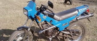
Bearings Ural Retro (IMZ-8.1036)
timeless classic, unforgettable '50s style: gleaming black polish contrasted with white markings, wood shift knob on the tank. Such a motorcycle is the Ural “Retro”. The magnificent black leather passenger seat, covered with buttons in the best classic traditions, and the sidecar, lined with velor on the inside, give this motorcycle real chic and charm.
Below is a table of bearings for the Ural-Retro motorcycle (IMZ-8.1036) of European specification, therefore all bearing numbers are internationally marked.
Bearing table Ural IMZ-8.1036
| Installation location | Number | Bearing type | Size | Qty |
| Engine (camshaft) | 6205/С31 (900006205002) | Ball radial single row | 25x52x15 | 1 |
| Engine (camshaft) | NK1816 (900001816001) | Needle bearing | 18x26x16 | 1 |
| Engine (crankshaft) | 6208-2RS2/C3 (900006208101) | Ball radial single row | 40x80x18 | 2 |
| Generator | 6004-2RS/C3 (900006004101) | Ball radial single row | 20x42x12 | 2 |
| Engine (rocker arms left and right) | NK1212 (900001212001) | Needle bearing | 12x19x12 | 4 |
| Clutch (rod tip) | BA 7 (900000007001) | Ball thrust single | 7x17x6 | 1 |
| Gearbox (primary shaft) | 6205-2RS/C3 (900006205101) | Ball radial single row | 25x52x15 | 1 |
| Gearbox (primary shaft) | 6204-2RS/С3 (900006204102) | Ball radial single row | 20x47x14 | 1 |
| Gearbox (secondary shaft) | 6304/C3 (900006304102) | Ball radial single row | 20x52x15 | 2 |
| Gearbox (secondary shaft) | K 25x29x10 (900252910214) | Needle bearing | 25x29x10 | 1 |
| Gearbox (secondary shaft) | K 26x30x13 (900263013214) | Needle bearing | 26x30x13 | 2 |
| Gearbox (secondary shaft) | K 25x29x13 (900252913214) | Needle bearing | 25x29x13 | 1 |
| Gearbox (shift pedal axis) | 6002-2RS/C3 (900006002101) | Ball radial single row | 15x32x9 | 2 |
| Gearbox (crankcase cover) | 6304/C3 (900006304102) | Ball radial single row | 20x52x15 | 1 |
| Final drive gear | 3304B (900003304101) | Ball double row | 20x52x22.2 | 1 |
| Final drive gear | 874901 (972105021001) | Needle bearing | 13x32x17 | 1 |
| Driven gear hub | 6207-2RS/C3 (800006207101) | Ball radial single row | 35x72x17 | 1 |
| Wheels (front, rear) | 6204-2RS (900006204101) | Ball radial single row | 20x47x14 | 2 |
| Damper | 32006 X/Q (900032006001) | Roller conical single row | 30x55x18.18 | 2 |
| Rear swingarm | 6201-2RS/C3 (900006201101) | Ball radial single row | 12x32x10 | 4 |
1 - designation C3 - increased thermal gap
2 - 2RS - closed on both sides
See also:
- Bearings Dnepr-16
- Bearings Gas-3110 "Volga"
- Bearings VAZ-1118 "Kalina"
- Bearings Izh-Jupiter, Jupiter 2, Jupiter 3, Jupiter 5.
- Bearings MMVZ-3.112 "Minsk"
- Bearings for concrete mixer PRORAB ECM 160Y.
- Bearings Dnepr - 11
- Bearings Zirka GN 121, Zirka GN 151.
- Bearings IZH-Planet Sport “PS”
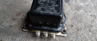
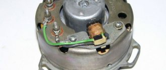
GENERATOR 500 W. REPAIR
AN INDEPENDABLE GUY WITH A BAD CHARACTER
“Ural” 500-watt generator 14.3771 - the unit is excessively noisy and not very reliable. But oppositionists, having tasted the charm of powerful light and forgotten about discharged batteries, prefer to put up with its shortcomings. And not to change it, but to repair it. In general, this is not difficult to do. We have already written about how to find a fault in the electrical circuits of a generator (“Moto” No. 3, 1998). Now we will assemble and disassemble the unit, and at the same time we will eliminate these same malfunctions.
First, remove the rectifier cover by prying it off with a screwdriver. If this is done carefully, the latch antennae securing it will not break. But later we recommend screwing an M5 nut onto the protruding ends of two opposite tightening bolts - it’s more reliable. Then unscrew the two screws securing the relay-regulator and carefully remove it complete with the brush assembly. The relay-regulator YA212A11E itself fails extremely rarely, but if this happens, know that in addition to the “native” one, similar 36.3702 or 361.3702, used on the generators of the Vladimirets tractors and modern Volgas with the ZMZ 406 engine, will be suitable. The differences between them are in the level of charging voltage: 36.3702 - 14.2 V, and 361.3702 -14.4 V. Higher voltage is useful at low temperatures and frequent short trips with light. During normal use, the “stepson” will cause a slight reduction in battery life.
1. Unscrew the castle nut securing the gear. This is not as easy to do as it seems at first glance - there is no flat on the rotor that you could grab with a key. The problem can be solved with the help of large pliers (hold the base of the gear, not the teeth!). When assembling, place a copper or brass washer under the nut - this will protect its threaded part from loosening.
content .. 11 12 19 ..REPAIR OF UNITS AND PARTS OF MOTORCYCLES “DNEPR” AND “URAL” - PART 2
Crank mechanism.
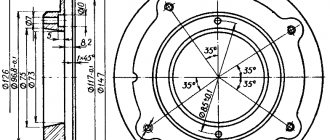
When assembling crank mechanisms for engines of motorcycles of the Ural and Dnepr-12 series, it is necessary to select two connecting rods based on weight that have the same marks on the lower head. The mass of the lower head of the connecting rods for the engines of the Ural M-62 and Ural-2 M-63 motorcycles in grams is indicated on its outer surface by the numbers 200, 202, 204, 206, 208, and for the Ural-3 motorcycles M- 66 and “Ural” M-67-36 - numbers 224, 226, 228, 230 and 232. Then the crank fingers are selected with the corresponding color indices, pressed into the front and rear axles with an interference fit of 0.124...0.170 mm. The location of holes “a” for lubrication with a diameter of 2.5...3 mm in the fingers must correspond to that shown in the figure
36.
Press the pins to a size of 94...94.4 mm between the thrust collars for bearings on the front and rear axles.
A set of rollers for connecting rods of motorcycle engines “Ural” M-62, “Ural-2” M-63 and “Dnepr-12” is selected in accordance with the color indices (size groups) of the crank pin and the hole of the lower head of the connecting rod (Table 7).
When installing connecting rods that have acceptable surface wear for the rollers, they are equipped with crank pins, indicated by a red index, and a group of rollers is selected that provides a clearance in the bearing of 0.010...0.025 mm.
Bearing 864708DM, consisting of rollers and separators, for the crank mechanism of the engine of the Ural-3 M-66 and Ural M-67-36 motorcycles is selected according to Table 8.
Table 8. Connecting rod roller groups
Assemble the crank mechanism in the following sequence. A set of rollers is selected that corresponds to the size groups of the pins and connecting rods, the rollers are inserted into the cage (the cage must have the same color index) and put on the pin with the connecting rod before assembly. Insert the axles with attached connecting rods into the device: the front axle - into its lower part, and the rear axle - into the upper part. Place a limit bar on the trunnion and, after checking with the control cheek, secure the trunnions with screws, then move the device apart and remove the control cheek. Heat the cheek in an electric furnace to a temperature of 380...400°C, take it out, center it with a finger and squeeze all the crankshaft parts in the device. Blow with compressed air. After this, the crankshaft is removed from the fixture and finally cooled in an oil bath. The cooled crankshaft is checked for assembly quality: the connecting rods should rotate without jamming, the end runout of the connecting rod along the journals in the bearings should be 0.045...0.14 mm for a new crankshaft and 0.045...0.3 mm for a repair one.
A special device must ensure the alignment of necks A and B (see Fig. 36) and the location of the fingers in a plane passing through the axes of these necks. The technological process of cooling the crank mechanism must prevent a decrease in the hardness of the working surface of the crank pin. The runout of surfaces A and B when installing the mechanism in the centers is permissible no more than 0.03 mm. It is measured at a distance of 5 mm from the neck. If the runout is more than 0.03 mm, editing is allowed. After assembling the crankshaft, grind the main journals of the axles and the cone for the flywheel to normal dimensions, for the bearing - with a diameter of 35-0.oi7 mm, and for the distribution gear - to a diameter of 30+odsh mm. Then install the oil catcher, tighten the fastening screws until they stop and drill the oil catcher metal into the slot on one side.
If the runout of the main journals exceeds the specified value, then the crankshaft must be adjusted with control using a device with centers and indicators (Fig. 37). The arrows of both indicators should deviate in one direction in one direction or another from zero (see Fig. 37, b, c). If the arrows show different values (see Fig. 37, a), then determine the highest point on the main journal (see Fig. 37, a - left journal) and, holding the crankshaft cheek in a vice, do not hit too hard with a lead or with a copper hammer on the left trunnion (see arrow in Fig. 37). If the indicator arrows show the same minus deviation, exceeding the permissible value, then blows with a hammer are applied inward (arrows, see Fig. 37.6). When the indicator arrows have a positive deviation, the trunnions are stretched (see arrows in Fig. 37, c), using a lever or a press (see Fig. 37, d).
The rotation of the crankshaft is checked at the centers with an indicator. To do this, insert a mandrel (Fig. 38) into the upper heads of the connecting rods, corresponding to the color index of the holes in the heads. Measure in two positions of the crankshaft (see Fig. 38, a, b).
The difference in measurements should not exceed 0.5 mm. In case of a larger size, the crankshaft is adjusted by hammer blows on the corresponding sides of the axles. Straightening the connecting rods of the assembled crankshaft is not permitted. When checking the crankshaft using the triangle method, the difference in indicator readings should not exceed 0.5 mm. The radial clearance of the lower head of the connecting rod should be no more than 0.012 mm, the axial clearance of the lower head of the connecting rod on the crank pin - 0.05... 0.034 mm. The connecting rods should rotate freely, without jamming.
To assemble crankshafts of motorcycles of the Dnepr series, assembled connecting rods are selected based on weight with the same color index from five groups: blue - 530±2.5 g, green -
535±2.5 g, red - 540±2.5 g, black - 545±2.5 g, white - 550±2.5 g. The color index is applied on the outer surface of the connecting rod cover.
The MT801201 crankshaft must be of normal or repair size, complete with normal or repair bearings. Before assembling the shaft, the lubrication lines are purged with compressed air. The assembled crankshaft with MT801-201 plugs and 242503P8 screw is drilled in two places and dynamically balanced with an accuracy of 100 Ncm, while ring weights weighing 477 ± 1 g are installed on both connecting rod journals. The center of mass of each weight must lie on the connecting rod axis cervix. When balancing, the holes in the shaft counterweights should be 10 mm in diameter and no more than 30 mm in depth. The displacement of the lines of the centers of the holes from the middle plane of the counterweights should be no more than 1.4 mm, the pitch of the holes should be no less than 15 mm. Before assembling the connecting rods, the crankshaft journals are lubricated with engine oil. When installing the liners, make sure that the fixing tendrils at their junction fit freely into the grooves on the cover and bed of the connecting rod. The cover must be tightened with the nuts of the connecting rod bolts using a torque wrench with a force of 32...36 Nm, while the nuts are lubricated with oil.
The connecting rods are installed on the crankshaft with protrusions on the connecting rod rods (indicated by arrows in Fig. 39), directed forward at the first connecting rod and towards the flywheel at the second. The surface of the liners is considered satisfactory if there are no burrs, chips, or pressed-in foreign materials. Dark surface color is not a rejection sign.
The liners suitable for further use must be elastic in order to be placed in the bed of the connecting rod bearing caps with the tension necessary for heat removal from the liners to the surface of the bed. Inserts that do not have interference in
beds are replaced. To replace worn or damaged liners, the plant supplies liners of normal and five repair sizes with a reduction of 0.05; 0.25; 0.5; 0.75; 1.0mm inner diameter. If there is slight wear on the connecting rod journals of a normal size crankshaft, you can use liners of a normal size or reduced by 0.05 mm. To install repair liners if the ovality and taper of the crankshaft journals is more than 0.03 mm, the journals must be ground and polished to the nearest repair size (Table 9). If the use of bearings of repair sizes does not provide the required clearances in the connecting rod bearings (in cases where the shaft has already been ground to the maximum reduction in the diameter of the journals), install a new crankshaft with bearings of normal size.
Table 9. Dimensions of the crankshaft connecting rod journal and the corresponding bearing
When repairing an engine, the bearings are replaced with new ones without any adjustment operations and only in pairs. Replacing one liner is not allowed.
22. Engine repair Engine cylinder
motorcycles K-750M and "Dnepr-12" is made of special
cast iron with hardness HB 207-255. If the cylinder has broken ribs with a total area of more than 15%, chips of the edges of the exhaust and inlet pipes on the inner surface with a depth of more than 10 mm, wear of the conical surface of the valve seat when the cone gauge sinks relative to the end of more than 2 mm, then such a cylinder is replaced. It is allowed to weld and process defective areas to normal size. In addition, the cylinder may have the following defects during repair:
- marks, scuffs, cavities on the conical surface of the valve seat - treat the surface of the seat until the defect is eliminated, but to a size at which the recess of the cone gauge relative to the end of the valve seat will be no more than 2 mm; - warping of the connector plane with the cylinder head is more than 0.1 mm - process the plane until the defect is eliminated, but to a size of at least 134.06 mm, and for “Dnepr” motorcycles—102 mm and “Ural”—94 mm; -wear of the surface of the cylinder mirror - measure the internal diameter of the cylinder
a bore gauge in five zones at distances of 9, 16, 64, 74, 84 mm from the upper plane of the cylinder in two planes: in the plane of swing of the connecting rod and in a plane perpendicular to it; if the ovality of the cylinder mirror exceeds 0.07 mm, and the taper or wear exceeds 0.15 mm, then the cylinder needs to be ground to the nearest repair size of the piston. The surface of the cylinder mirror is finally finished using a honing process. Ovality and conicality are allowed no more than 0.015 mm, non-perpendicularity of the cylinder mirror axis to the reference plane of the cylinder flange should not exceed 0.06 mm over a length of 100 mm; - wear of the surface of the valve guide hole to a diameter of more than 9.25 mm -
machine the hole to a diameter of 13+0.035 mm for the adapter sleeve, which also needs to be pressed in and then expanded to a normal diameter of 9+0.03 mm; - nicks on the plane of the connectors with the crankcase - clean the defective plane until the defect is eliminated, but to size “a” of at least 134.06 mm, and for motorcycles “Dnepr” - 102 mm and “Ural” - 94 mm;
- loosening of the fit of the studs when the threads in the hole are broken by more than two threads - drill the hole and cut a thread of repair size M10 for the repair stud.
For boring, the cylinder is installed in the chuck of a 1A62 type lathe and bored with a cutter with a VK-2 hard alloy plate at a cutting speed of 137 m/min, at a spindle speed of 475 min-1 and a feed of 0.125 mm/rev. The honing allowance should be 0.04…0.06 mm. The cylinder mirror can be honed on a vertical honing machine ZA833 using abrasive stones K3120ST2-T2K, K3180ST2K during preliminary processing and K3280SM2-S1B, K3400SM2 and M20ST2-T2K during final processing.
Operating mode on the machine: spindle speed - 180 min-1, cutting speed - 51 m/min, reciprocating speed of the honing head - 20 m/min.
When honing, coolant is supplied generously - kerosene or a mixture of kerosene with 10...20% engine oil. Both cylinders are machined to only one repair size. In the absence of a honing machine, this processing can be carried out on a lathe or radial drilling machine, using a honing head with springs under the stones.
After finishing the processing of the cylinder mirror to remove abrasive dust, its surface is washed with warm soapy water and a hair brush or kerosene and a brush, then dried in air. The surface roughness of the cylinder mirror should be no more than 0.32 microns; To increase wear resistance and reduce the surface roughness of the cylinder mirror, it can be rolled in with a vibrating ball. Figure 40 shows the repaired engine cylinders of the Dnepr K-650, MT-9, MT-10-36 and Ural series motorcycles with pressed liners, and Figure 41 shows the cylinders of the K-750M and Dnepr-12 motorcycles.
Piston rings
. Before installing new piston rings, they must be fitted to the piston groove (see page 61). The gap in the lock is measured at the ring inserted into
cylinder without distortion. It is convenient to align the position of the ring in the cylinder with a piston inserted after the ring. The gap should be 0.04...0.08 mm for compression rings (only for new ones), for oil scraper rings - 0.025..0.065 mm. When installing piston rings into the cylinder, there should be no clear gap around the circumference between the ring and the cylinder; a clearance of up to 0.12 mm is allowed over a total length of no more than 1/4 of the circumference.
If there are no factory-made piston rings, they can be made from a cast thick-walled fine-grained cast iron pipe with an outer diameter of 80...85 mm and a bore diameter of 55...60 mm. The pipe is fixed in the chuck of a lathe and machined along the outer and inner diameters in one installation, ensuring a surface roughness of 0.63 microns. Then the rings are cut off with a small allowance for finishing. The fitted ring is cut with a hacksaw blade, specially ground on an emery wheel to a thickness of 0.5...0.8 mm. To give the ring elasticity, it is first separated at the joint by a distance of 12...15 mm, for which the cut rings are put on a pipe of a suitable size, together with the pipe they are heated to a temperature of 800...900°C and held for 20...25 minutes, after which they are cooled in oil . Then the rings are heated again to 350...400°C and slowly cooled in air. The manufactured rings have the correct shape, but do not have the elasticity of factory rings.
When assembling, the rings are put on the piston sequentially, using a special device or plates that ensure minimal separation of the rings at the joints. The inserted rings must move freely in the piston grooves. This is checked by shaking the piston washed with kerosene; The rings must fit freely into the piston grooves.
Piston
. The permissible wear of the piston pin hole should not exceed 0.02 mm. If the holes for the piston pin and the grooves for the piston rings are worn beyond acceptable levels, as well as if there are burrs on the skirt, the pistons are replaced. When replacing pistons for the first time in slightly worn cylinders that do not require boring or grinding, install pistons of a normal group size corresponding to the actual size of the cylinder. When boring cylinders, pistons of the appropriate repair size are installed, ensuring a gap between the piston skirt and the cylinder surface of 0.08...0.10 mm. Along with selecting the piston to the cylinder according to the diameter of the skirt, they should be selected by weight. This is necessary for the balance of the engine. The difference in the weight of the engine pistons should not exceed 4 g. The piston assembly with rings and pin must be weighed. For selected pistons, the color marking of the holes for the piston pin must correspond to the marking of the hole in the upper head of the connecting rod. Marking paint is applied on the pistons to the lower surface of one of the bosses, on the connecting rods - at the upper head. This will allow you to select the correct piston pin.
Piston pin
. Inspect the outer surface of the finger, check for scratches, nicks, enveloping of bronze and noticeable wear. Piston pin wear is measured at the edges and in the middle, wear should not exceed 0.015 of the minimum color marking size. When replacing the crankshaft, the bushing in the upper head of the connecting rod, the piston or the pin itself, the new pin is selected according to the color marking (applied to the inner surface at one end), which must match the color marking of the holes in the piston and the upper head of the connecting rod.
The piston pin can be restored by chrome plating followed by grinding to normal size 21Io!oi4 or permissible 20.986 mm, ensuring during assembly a clearance in the bushing of the upper connecting rod head of 0.0045...0.0095 mm and interference in the piston bosses
0.0045…0.0095 mm.
Cylinder head
. Inspect all accessible places in the cylinder head, check for breakdowns, cracks, burnouts, thread breaks, and the flatness of the mounting surfaces of the head to the cylinder and carburetor. The cylinder head of the K-750M and Dnepr-12 motorcycle engines is made of aluminum alloy AL10V with a hardness of HB 65. If the head has cracks, breaks of any size and location (except for cracks and broken ribs), thread failure of more than two threads in the spark plug fitting , then it is replaced. During repairs, the head may have the following defects:
— cracks, broken ribs with a total area of up to 15% of the fins — clean up the broken areas;
- warping of the parting plane of the head with the cylinder is more than 0.075 mm - process the plane until the unacceptable warping is eliminated.
To inspect the cylinder head of the Ural and Dnepr motorcycle engines (Fig. 42), remove the valves using pullers (see Fig. 26). If they are missing, proceed as follows: install the head with valves on a wooden support; apply a piece of metal tube with an internal diameter sufficient for the free passage of crackers to the spring bearing, and lightly hit the end of the tube with a hammer; both crackers will come out of their nest after one or two hits. Then remove the upper spring plates, springs and lower plates and take out the valves. The head may have defects:
— wear of the hole in the guide bushing to a diameter of more than 8.13 mm — expand the hole for the repair valve stem;
— weakening of the fit of the guide sleeve — process the hole to the nearest repair size 14.1+0.035; 14.2+0.035; 14.3+0.035; 14.4+0.035; 14.5+0.035 mm for the repair sleeve;
— weakening of the fit of the exhaust valve seat when the seat hole in the head is worn to a diameter of more than 38.07 mm — process the hole to the nearest repair size;
— wear of the surface of the hole for the rocker axis — machine the hole to a repair size of 10.105; 10.205; 10.305; 10.405; 10.505 mm for the repair axle of the rocker arm;
— loose fit of the pins — replace the defective pin. The landing of pins on red lead is allowed;
- weakening of the fit of the rocker arm axis when the mounting hole in the head is worn to a diameter of more than 15.045 mm - replace the stand or expand the hole to a repair size of 15.1+0.035 mm for the repair stand;
- loose fit of the pipe - replace the pipe, ensuring an interference fit of 0.04 mm;
- threads on studs are broken by more than two threads - replace the stud.
To replace the guide bushing, the cylinder head is secured in a vice, a mandrel is inserted and the guide bushing and valve are pressed out; check the condition of the hole for the guide bushing; heat the head to 200°C and, putting the guide bushing on the mandrel, press the bushing into place, maintaining 20 mm from the support plane of the lower spring plate to the edge of the bushing; ream the hole of the guide bushing with a reamer to 8.00...8.03 mm and check the straightness of the hole with a caliber of 7.98 mm in diameter and 50 mm in length. The gauge must pass under its own weight along the entire length of the sleeve. If the bushings are metal-ceramic, they must be soaked in engine oil for 1.5...2 hours before pressing.
After repairing the guide bushing, it is imperative to check the misalignment of the valve seat chamfer and, if necessary, grind or grind the valve seat chamfer with a cone. Particular attention is paid to checking the condition of the seating chamfers of the valve head and valve seat, since engine compression and, consequently, engine power and gasoline consumption depend on this.
The valves are made of steel 4Х9С2, 4Х9Г2, 5Х20Н4AGEМ and have a rod surface hardness of HRC 48-54, the rest of the hardness of the rod is 255-302. If there are cracks or breaks, the valve is replaced.
During repairs, the valve may have the following defects: warpage of the valve disc of more than 0.04 mm - treat the conical surface of the valve at an angle of 45° to the axis of the valve stem until the defect is eliminated, but to a cylindrical flange size of at least 0.5 mm;
- burnout, scuffing, nicks or wear of the surface of the plate cone when the height of the cylindrical part is more than 0.5 mm - grind the surface of the plate, but to a cylindrical belt size of at least 0.5 mm and a plate diameter of at least 37.2 mm;
— wear of the surface of the valve stem to a diameter of less than 7.85 mm — restore the surface of the stem by chrome plating and grind to a size that provides a normal or permissible clearance of 0.2 mm with the mating part;
- the valve rod is bent more than 0.02 mm - straighten the rod on the aluminum plate with blows of a lead hammer until the unacceptable bent is eliminated;
- local wear, nicks on the end surface of the valve stem - treat the surface until the defect is eliminated, but to a length of not less than 136.3 mm for K-750M and Dnepr-12 motorcycles, not less than 90.7 mm for exhaust and 91 .7 mm at the intake
- for Ural motorcycles and at least 91.8 mm - for Dnepr motorcycles.
If the valve seats and heads are slightly worn and the valve fits over the entire surface, and the fit zone is within 1.5...1.8 mm, you can limit yourself to
cleaning and grinding the working chamfers of the valve and seat.
If the valve seat has a large wear or other defects and grinding cannot remove them, then the valve seat is replaced with a new one, for which it is necessary: use a special tap to cut the thread in the valve seat, then heat the head to 200°C, tighten the puller screw as shown in the figure 43, and remove the saddle. You can cut the seat into three parts with an emery disc and remove it piece by piece, then bore the seat to one of the repair sizes using a tool (Fig. 44) or fit the repair seat to the old hole, taking into account the permissible interference of 0.2...0.25 mm.
Repair dimensions of the seat socket -38.3+0.05; 38.4+0.05; 38.5+0.05; 38.6+0.05; 38.7+0.05
mm (only for Ural motorcycles). For the intake valve of Ural motorcycles and both valves of Dnepr motorcycles, the mounting hole is machined to repair dimensions of 41.3 + 0.05; 41.4+0.05; 41.5+0.05; 41.6+0.05; 41.7+0.05 mm also for repair valve seat.
Before pressing, the seat is cooled in liquid nitrogen to a temperature of minus 75...100°C
and using a mandrel, press it into the socket until it stops. Before pressing, a cast iron seat is lubricated with a saturated ammonia solution, and a bronze seat is lubricated with engine oil. In the absence of nitrogen, the cylinder head is heated to a temperature of 380...400°C before pressing the seat, in this case the seat easily fits into its seat with little pressure on it. After pressing, the seat is processed with cone cutters or cutters.
After lapping, thoroughly wash the valves, valve seats, guide bushings, neck and combustion chamber of the cylinder heads until the lapping paste is completely removed
and wipe dry. After this, check the tightness of the valves, for which they put the valves in place and, pressing the valve heads to the seat, alternately pour kerosene into the suction and exhaust channels of the cylinder head. There should be no leakage of kerosene for 1 minute. If kerosene leaks out earlier than the specified period, additional, more thorough grinding is required.
content .. 11 12 19 ..
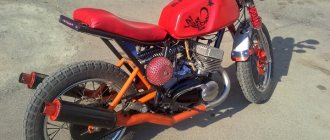
Japanese bearings for the Dnieper engine.
To increase service life, I decided to replace the crankshaft main bearings and camshaft bearings with high-precision imported ones. The analogues of our 204, 205, 209 are 6204, 6205, 6209, respectively. The analogue of the roller 4209k is nj209. I ordered all four from bearing.ru. I understood perfectly well that it would cost a decent amount. The first three ball ones roughly fit into what I expected. About 1 thousand. But the roller one shocked me. Nj209 produced by skf costs 1720 kopecks. In this regard, doubt crept into my soul. Is it really necessary to have a rear root of Japanese origin, especially since I already have a new 4209k produced by the 10th Ukrainian gas processing plant, which is known for its good quality. It seems to me that I will change my knee before this bearing dies.
turn for dynamic balancing. with flywheel (crown) and clutch discs.
how much for ball ones? I'm especially interested in 6209.
p_s, Esseseno. 6205 and 6204 for about 250 rubles. 6209 approximately 650 rub. I do not remember exactly. But I can’t find letters with prices.
and the posterior molar. x.z. it is not as loaded as the front one. They seem to be working fine. There are no statistics. But I haven’t heard of anyone’s blown apart yet. there are no axial loads. I don't know, think for yourself.