How does the checkpoint work?
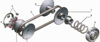
The KPP-141 device, installed on some Ural models, includes the following elements:
- Coupling mechanism. It helps temporarily separate the engine and transmission. This allows you to change gears without reducing the speed of the power unit.
- Driven gears and shafts. The drive, intermediate and secondary shafts are installed here.
- Synchronizer. It ensures silent operation of the mechanism and equalization of gear speeds.
The gears rotate freely when the neutral mode is engaged, at which time all clutches and synchronizers are in the open position. When the driver begins to squeeze the clutch mechanism and shifts the handle to some other gear, a special fork device begins to move the clutch into the engagement position with the corresponding pair at the end of the gear.
The gear mechanism is rigidly fixed to the shaft and stops spinning on it. The clutch in this position facilitates the transmission of rotational motion and traction force.
While the vehicle is moving, the gearbox is activated by the gear shift knob. It moves sliders equipped with forks, which begin to move the synchronizers at the required speed. A color diagram of gear shifting is in the Ural user manual.
Gear ratios of the Ural box:
- first stage - 5.26;
- second stage - 2.90;
- third stage - 1.52;
- fourth stage - 1.00;
- fifth stage - 0.664;
- reverse gear - 5.48.
Spare parts for Ural, Kraz, MAZ, Kamaz trucks. Engine parts YaMZ-236, YaMZ-238
__________________________________________________________________________
__________________________________________________________________________
Gearbox for Ural-4320, Ural-5557 vehicles
___________________________________________________________________________
Until 1994, Kamaz-141 gearboxes (for the Kamaz-740 engine) were installed on Ural-4320 and 5557 vehicles. Since 1994, Ural-4320 vehicles and their modifications have been equipped with YaMZ-236 engines with a YaMZ-236 gearbox or with a YaMZ-2361 gearbox (a modernized version of the YaMZ-236 gearbox). Gearbox Ural-4320, 5557 (YaMZ-236) Gearbox YaMZ-236 for Ural-4320, 5557 vehicles - mechanical, three-way, five-speed (five gears for forward movement and one for reverse) with synchronizers for 2–3 and 4–5 transmissions Modification of the gearbox - YaMZ-236U. Gear ratios of the gearbox Ural-4320, 5557 YaMZ-236 U Transmission Gear ratios 1 5.26 2 2.90 3 1.52 4 1.00 5 0.664 Reverse 5.48
Rice. 13. Gearbox of Ural-4320, 5557 (YaMZ-236) vehicles 1– clutch release clutch; 2–primary shaft; 3, 15 – bearing caps; 4–clutch housing; 5, 10 – synchronizers; 7 – retainer ball; 8, 22–fifth gear gears; 9, 21–third gear gears; 11, 19 – second gear gears; 12–first gear and reverse gear; 13–top cover; 14–secondary shaft; 16–flange; 17 – intermediate shaft with first gear gear; 18–gearbox housing; 20–oil pump intake with magnet; 23– power take-off gear; 24–intermediate shaft drive gear; 25–oil pump; 26–axis of the reverse gear block; 27–reverse gear block; 28–speedometer drive gear. Primary shaft 2 (Fig. 13) of the Ural-4320, 5557 gearbox is mounted on two ball bearings. The front bearing is pressed into the engine crankshaft bore. During assembly, the bearing cavity is filled with Litol-24 lubricant and sealed with a cuff. The rear bearing is secured against axial movements in the front wall of the gearbox housing and the bearing cover using a retaining ring. The front end of the secondary shaft 14 rests on a roller bearing placed in the socket of the primary shaft. The rear end of the secondary shaft of the Ural-4320, 5557 gearbox rests on a ball bearing secured by a retaining ring in the crankcase wall and cover. A flange 16 is installed on the splines of the rear end of the secondary shaft for fastening the propeller shaft of the vehicle. The intermediate shaft 17 is mounted on two roller bearings. The front end of the intermediate shaft of the Ural-4320, 5557 gearbox has a groove for driving the oil pump. The reverse gear block 27 rotates on two roller bearings mounted on a fixed axis 26. All gears of the Ural-4320, 5557 gearbox have spiral teeth, except for the spur gears of the first gear, the reverse gear and the power take-off gear. The second, third and fifth gears and a pair of intermediate shaft drive gears are in constant mesh. The gears of the second, third and fifth gears of the secondary shaft are mounted on steel plain bearings with a special configuration, coating and impregnation. Shockless engagement of the second, third, fourth and fifth gears is ensured by two synchronizers 6 and 10. The Ural-4320, 5557 inertial type gearbox synchronizer allows the gear coupling of the carriage to engage with the gear coupling of the gear only when the angular velocities of rotation of the gear and shaft are equalized. The speed equation is carried out using a friction pair - a synchronizer cone ring and a cone on the gear. Engaging first gear and reverse gear is carried out by moving gear 12 along the splines of the secondary shaft until it fully engages with the corresponding gear. The top cover of the Ural-4320, 5557 box contains a three-way gear shift mechanism. On the rods of the Ural-4320, 5557 gear shift mechanism, forks are attached, which, when the rods move, move the synchronizer carriages or the first gear and reverse gear. The rods are held in the desired position by ball retainers 7. To protect against accidental engagement of two gears at the same time, the Ural-4320, 5557 gearbox has a locking device (type A–A), consisting of a pin and two pairs of balls; when any rod moves, the other two are locked balls that fit into the corresponding grooves on the rods. To protect against erroneous engagement of reverse gear and first gear, spring fuse 32 is used. To engage reverse gear or first gear, the additional force of the fuse spring must be overcome. Through gear 23 (Fig. 13), power can be taken to drive additional units. The power take-off mechanism is attached to one of the flanges with hatches located on both sides of the gearbox housing. The Ural-4320, 5557 gearbox is equipped with a speedometer drive mechanism located in the cover 15 of the rear bearing of the secondary shaft (view B-B).
Rice. 14. Diagram of the lubrication system of the Ural-4320, Ural-5557 gearbox A – oil suction; B—high blood pressure; 2–oil intake magnet; 3–oil intake mesh; 4–drain plug; 5– oil pump; 6–reducing valve; 7–filler plug The lubrication system of the Ural-4320, 5557 gearbox is mixed (Fig. 14). The sliding bearings of the secondary shaft gears are lubricated under pressure. Rolling bearings, gears and the gear shift mechanism of the Ural-4320 are splash lubricated. Oil is sucked from the crankcase oil bath through the intake and channel system by gear oil pump 5, installed on the front wall of the gearbox housing and driven from the intermediate shaft. The oil intake is closed with a mesh 3 and has a permanent magnet 2 to catch small metal particles in the oil. The oil pump is equipped with a pressure reducing valve 6, adjusted to a pressure of 80±10 kPa (0.8±0.1 kgf/cm2). Oil is poured into the Ural-4320 gearbox through a hole in the top cover, closed with a plug, to the level of the control hole located on the left side of the crankcase. The filling capacity of the Ural-4320 gearbox lubrication system is 5.5 l. The internal cavity of the Ural-4320, 5557 gearbox housing communicates with the atmosphere using a breather. During maintenance, check the fastening of the Ural-4320 gearbox to the engine and the condition of its suspension, maintain a normal oil level in the box and promptly replace it according to the lubrication table.
Rice. 15. Transmission plugs Ural-4320, 5557 (YaMZ-236) 1 – oil filler hole; 2–oil pump intake cover; 3–oil level inspection hole; 4–drain hole The oil level in the gearbox housing must not be lower than the lower edge of inspection hole 3 (Fig. 15). Drain the oil from the Ural-4320, 5557 gearbox housing while hot through the drain hole closed with plug 4. After draining the oil, clean the magnet of the drain plug. After draining the oil, unscrew the bolts and remove cover 2 of the oil pump intake, clean and rinse the mesh, and then replace the cover. When installing the intake cover, be careful not to block the oil line with the cover or its gasket. It is recommended to wash the Ural-4320, 5557 gearbox with industrial oil I-12A or I-20A in accordance with GOST 20199 - 88; 2.5 - 3 liters - pour it into the gearbox crankcase, set the gear shift lever to the neutral position, start the engine for 7...8 minutes, then stop it, drain the flushing oil and fill with fresh oil. It is strictly forbidden to flush the Ural-4320, 5557 gearbox with kerosene or diesel fuel in order to avoid failure of the oil pump due to insufficient suction vacuum and, as a result, failure of the gearbox. In case of complete overhaul of the Ural-4320 gearbox, lubricate the oil pump with the oil used in the gearbox before installation. When towing a car with the engine not running, the input and intermediate shafts of the Ural-4320, 5557 gearbox do not rotate, the oil pump in this case does not work and does not supply lubricant to the bearings of the secondary shaft gears and to the cone surfaces of the synchronizers, which will cause scuffing of the sliding surfaces and wear of the rings synchronizers and leads to failure of the entire gearbox. To tow, disengage the clutch and engage direct (fourth) gear in the gearbox or disconnect the gearbox from the transmission. Towing a vehicle over a distance of more than 20 km without disconnecting the driveshaft or squeezing the clutch with the direct transmission engaged is not allowed. To prevent premature wear of the rubbing pairs, it is recommended to warm up the gearbox before starting the engine at an ambient temperature below -30°C. If this is not possible, then drain the oil from the crankcase while the engine is stopped for a long time, and before starting the engine, heat this oil and pour it into the Ural-4320 box through the hole in the top cover. For smooth and easy gear shifting and protection of the teeth of the intermediate shaft and six gears of first gear and reverse gear from end wear, as well as protection of rings. synchronizers from wear, properly adjust the clutch and prevent it from “driving.” Gearboxes Ural-4320, Ural-5557 (YaMZ-2361) The YaMZ-2361 gearboxes are a modernized modification of the YaMZ-236 family of gearboxes. On the Ural-4320, 5557 gearboxes of the YaMZ-2361 type, a reinforced input shaft was introduced by increasing the shaft diameter, the input shaft seal and the lubricant supply system from the oil pump to the input shaft cover were changed. The lubricant is supplied through an oil pipeline from the oil pump to the input shaft cover. Gearbox model YaMZ-236U - after change - YaMZ-2361-50 The Ural-4320, 5557 gearbox assembly complete with a diaphragm-type clutch is interchangeable when replacing the driven clutch disk 182.1601130 with 182.1601130-10 with an increased inner diameter of the hub and clutch release clutch 183.1601180 -01 to 184.1601180-31. The name and designation of parts of the Ural-4320, 5557 gearboxes complete with a diaphragm-type clutch before and after changing the gearbox are given in the table. Name of the part, gearbox unit. Part designation (Before change), Quantity / Part designation (After change), Quantity Primary shaft with tube assembly 236Н-1701027-Б 1 / 2381.1701025* 1 Primary shaft cover 236-1701040-А 1 / 2381.1701040 1 Oil pump 236-1704010 -A 1 / 336.1704010-10 1 Gasket 236-1704017-A2 1 / - - O-ring - - / 336.1704019 1 Pipeline - - / 336.1704300 1 Cuff 236-1701230 - / 201.1701230 1 Bolt M1 6x1.5-6 — — / 310264- P29 2 Gasket — — / 201.1015624 4 Thrust ring — — / 201.1721413 3 Note: * — Primary shaft with rear bearing and tube assembly. For the conversion of Ural-4320, 5557 gearboxes of the YaMZ-236 type into gearboxes, respectively, of the YaMZ-2361 type, a set of spare parts 2361.1700200 was created, including the parts and assemblies necessary for replacement.
_________________________________________________________________________
_________________________________________________________________________
_________________________________________________________________________
- Cardan shafts and power take-off Ural-4320
- Transmission gearbox Ural-4320
- Bridges Ural-4320
- Transfer case Ural-4320
- Steering Ural-4320
- Truck cranes and cranes based on trucks
_________________________________________________________________________
_________________________________________________________________________
- Cylinder block and cylinder head YaMZ-236 HE2, YaMZ-236 BE2
- Checking and adjusting YaMZ-236
- Power system and lubrication system YaMZ-236
- Driven and driven clutch discs YaMZ-236, 238
- Cooling and lubrication systems YaMZ-238
- Fuel injection pump YaMZ-238
_________________________________________________________________________
- Kamaz diesel engine
- Repair and adjustment of Kamaz power steering
- Kamaz-152 gearbox with divider
- Gearbox parts for Kamaz-5320 gearbox
- Kamaz transfer case and driveshafts
- Kamaz gearbox repair
- Clutch KamAZ-5320
- Construction of Kamaz-4310 drive axles
- Power steering MAZ-5551, 5549, 5335, 5336, 5337
- Front axle and steering rods MAZ-5551, 5549, 5335, 5336, 5337
- Clutch adjustment MAZ-5551, 5549, 5335, 5336, 5337
- Adjustment and repair of gearboxes MAZ-5551, 5549, 5335, 5336, 5337
- Repair and maintenance of the rear axle MAZ-5551, 5549, 5335, 5336, 5337
- Front axle parts and steering rods MAZ-5516, 5440
- Steering Maz-5516, 5440
- Details of driving axles Maz-5516, 5440
- Clutch device ZIL-130
- Repair of ZIL-130 gearbox
- Repair of rear axle ZIL-130
- Basic parts of the ZIL-130 engine
- Transfer case and power take-off ZIL-131
- Drive axles ZIL-131
- Steering ZIL-131
- Maintenance of ZIL-645 engine parts
Malfunctions and repairs
Basic malfunctions and repairs of the box:
- Extraneous noise in the mechanism. In this case, it is recommended to conduct an external inspection of the system and replace damaged and worn parts.
- The shafts move along the axis. It is necessary to replace the parts that secure the bearing, or replace failed bearings.
- Unstable operation of the gearbox. This problem may be due to wear on the reverse spline shaft bushings. Damaged mechanisms should be replaced.
- The clutch does not engage fully. In this case, it is recommended to conduct an external inspection of the coupling mechanism for damage and defects, check the level of lubricating fluid in the system and replace damaged elements.
- The fork rods are difficult to move. This malfunction can be caused by damage to the locking pins and synchronizers. It is necessary to replace the mechanisms with new ones.
- If the gearbox switches off spontaneously, it is necessary to adjust the gap between the valves, replace worn synchronizer rings, install new springs, and tighten fasteners.
- If the switching is unclear, you need to remove the cover of the locking device and inspect the main components for wear, replace the clutch and gears.
Gearbox repairs are carried out only with the power unit turned off.
How to adjust
The gearbox is adjusted as follows:
- The vehicle is installed on a special platform.
- Using a jack, slightly raise the front part of the car body and fix it in this position.
- On the transmission control rod, loosen the fastening nuts of the clamp bolt. The nut is loosened 4.5 turns.
- Using a screwdriver, expand the grooves at the end of the traction device and the clamp.
- Move the rod to the neutral position.
- Unscrew the special fasteners.
- Remove the gearbox cover from the control handle. The cover is lowered to the very bottom of the case, and the handle itself is placed in a vertical position with the end up.
- Loosen the clamp mechanism.
- Engage reverse gear when the power unit is not working.
- Install the prepared template into the trim window, as well as the reverse locking bracket.
- The stop of the axial mechanism is inserted into the groove of the template and pressed against the system body.
- Set the required gap between the elements. Tighten the fasteners and clamp.
- Start the engine and check the serviceability of the adjusted gearbox.
How much oil to fill
Oil must be added in accordance with the user instructions. For Ural cars, the sufficient oil fluid level is 3.5-4 liters.
Characteristics of gearbox problems
In order for the high-speed gearbox to serve for many years, the owner of the Ural car must maintain it efficiently. Caring for the transmission system is as follows:
Let's list the main reasons why box breakdowns occur:
The need to diagnose the Ural 4320 gearbox arises if gear shifting becomes difficult and increased noise from the transmission begins to occur. If there is a breakdown of the gear teeth in the Ural 4320 gearbox, then because of this, while moving on the road, a characteristic noise will be noted from the side of the box. However, the appearance of noise may be directly related to the fact that there is a low amount of fuel in the gearbox.
In most cases, oil leakage is a consequence of natural wear and tear of the rubber seals. These consumables are not restored, but replaced with new ones. At the same time, their prices remain at an affordable level.
When adding new transmission oil, you must follow the established requirements. On the Ural-4320, you can check the level of available oil using the existing indicator.
It is necessary to check the condition of the transfer case if it becomes difficult to shift gears. As a rule, this occurs due to the fact that nicks have appeared on the couplings.
Oil should be added to the transfer case through the top hatch. The transfer case requires about 3.5 liters of fuel. For high-speed gearboxes, it is recommended to use TSp-15K (mineral) gear oil. This fuel is used by many heavy-duty vehicles. The viscosity category of TSp-15K is as follows – 80W90. Using high-quality oil helps reduce wear of rubbing parts.
Since URAL vehicles are subject to heavy loads, you need to pay attention to the clutch mechanism. In some cases, if it is damaged, gears may not engage properly. If it is difficult to change gears, first of all you should pay attention to the integrity of the rods and synchronizers. Repair and restoration work is best left to experienced professionals.
It is prohibited to continue operating a truck with worn engine or transmission mechanisms; urgent repairs are required. The box must be completely sealed. A number of deformed parts can be restored by using methods such as welding and melting. To carry out professional gearbox repairs, appropriate equipment is required. Repair of the Ural 4320 gearbox must be carried out in a timely manner.
Source
How to remove and disassemble
In order to dismantle and disassemble the gearbox, you must:
- Place the vehicle on a lifting device or inspection pit.
- Remove the batteries, air filter element and mudguards. They are located at the bottom of the engine compartment, in the center and along the edges.
- Remove the front suspension cross member and the front drive wheel drives.
- Drain the transmission fluid from the box.
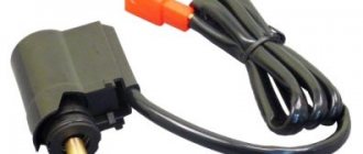
- Disconnect the wires of the sensor responsible for speed indicators. To do this, you need to pry up the wires with a screwdriver and carefully remove the spring retaining device.
- Remove the vehicle reverse switch.
- Remove the engine harness holder.
- Remove the mounting bolts from the gearbox and the hydraulic clutch release bracket.
- Remove the bolts from the working cylindrical block, clutch housing, amplifier.
- Remove the crankcase.
- Place a support under the dismantled box.
- Disconnect the front and rear supports from the bracket.
- Move the gearbox back and place it on a hard surface.
- Unscrew the fasteners and disassemble.
Dismantling the transfer case
It is more convenient to remove the transfer case if the car is installed on an inspection ditch in a room equipped with a lifting device.
Remove the driveshaft of the middle axle drive, disconnect the flanges of the driveshafts of the intermediate, front axle drive and front winch drive from the flanges of the transfer case and the additional power collection box.
Disconnect the wires from the speedometer sensor.
Undo the cotter pins and remove the pins, disconnect the rear ends of the control rods for the transfer box, auxiliary power take-off box and parking brake.
Unscrew the sealing tube from fitting 11. Move the disconnected ends of the cardan shafts and control rods of the transfer case, additional power take-off and parking brake to the side and secure them to the vehicle frame.
Fasten the load-lifting device to the bracket on cover 4 of the top hatch of the transfer case and lightly tighten the slings of the lifting device.
Undo the cotter pins and unscrew the nuts of the studs securing the transfer case to the brackets, remove the cushions and washers, carefully lower the box onto the trolley and remove it from under the car frame.
How to assemble and install
Box assembly procedure:
- compress the bearing;
- insert a chisel into the gap between the end part of the inner bearing ring and the differential box;
- install the bearing and axial mechanism of the satellites;
- insert the support ring into place;
- install drive gears and differential box;
- tighten the fasteners;
- install the synchronizer blocking ring;
- install the sliding clutch and retaining ring of the synchronizing device hub;
- install the driven gear and thrust washer;
- adjust the gap between the front bearing ring and the drive gear.
Operation and Maintenance
Maintenance can be of the following types:
The driver must carry out daily maintenance before the vehicle leaves the road and upon returning to the garage.
Maintenance during the initial period of operation is carried out after 1000 km of run, seasonal - 2 times a year (spring and autumn). TO1 is carried out every 4,000 km, and TO2 - after 16,000 km.
Such work includes checking the oil level, inspecting the main components and devices, as well as adjusting the coupling mechanism and clearances.
How to start a Ural
In order to start the Ural engine, you must:
Ural motorcycle gearbox with reverse speed
How to independently remove, disassemble and assemble the gearbox of a Ural motorcycle.
Over its long life, the gearbox of the Ural motorcycle has undergone several modifications, including the addition of a reverse gear. The use of a secondary shaft in the gearbox made it possible to increase productivity and significantly reduce the size of the box, which is very important for a motorcycle. Repairing and assembling the gearbox of a Ural motorcycle is not very difficult, and this work can be done independently.
Diagram of the URAL 4320 car
The layout of the URAL 4320 vehicle is specially designed for transporting goods, people, and installing various equipment, including special-purpose ones.
Diagram of the URAL 4320 car
The design of the URAL 4320 is based on a one-piece high-strength body with a 4 × 4 or 6 × 6 chassis wheel arrangement, depending on the configuration and installed engine.
Scheme URAL 4320 general device
The suspension diagram of the URAL 4320 car is dependent on springs with shock absorbers of double-sided functioning. The rear suspension on the URAL 4320 scheme is also dependent on springs with reaction bars.
Scheme URAL 4320 - frame and suspension
In the suspension diagram of the Ural-4320 car, all axles are driven, due to which the car has high cross-country ability.
How does a Ural motorcycle gearbox work with reverse gear?
The two-shaft gearbox of the Ural motorcycle uses fewer gears when transmitting torque, which is the main reason for the increased efficiency. The input shaft of the gearbox has three initial speed gears, which are integral with the shaft. The purpose of the secondary shaft is to select the required gear, and the gears on it are not rigidly fixed. The gearbox of the Ural motorcycle with reverse speed has manual and foot shift methods, which makes it very convenient to use.
On later modifications of the gearbox, a removable rear cover appeared in the aluminum crankcase, allowing the gearbox to be repaired without removing it from the engine.
Among other motorcycles, it is precisely the ease of maintenance that distinguishes the Ural motorcycle - a major overhaul of the gearbox can be easily completed within a day, if the appropriate spare parts are available. It must be remembered that some parts from various modifications of the gearbox are interchangeable. This is one of the main advantages that makes it quite easy to assemble a working box from several faulty ones.
Transmission system components
Ural vehicles are valued for their high power characteristics, excellent load capacity, and driving dynamics. The performance indicators of this vehicle are largely influenced by the installed gearbox. This device affects power gain.
The Ural-4320 is equipped with a five-speed gearbox. It has a long service life and can withstand the loads placed on it well. The Ural gearbox housing is attached to the clutch housing. The manual transmission on the Ural car has fixed shaft axles. The upper crankcase cover is equipped with a gear shift mechanism.
Gearbox diagram
The transmission system includes lockable cross-wheel and center differentials. On the truck there is a dependent power take-off box or KZOM.
It should be noted that there is a transfer case on the Ural 4320. It is 2-stage and affects the fuel consumption for each kilometer traveled. This box is securely fixed to the frame with several special rubber pads.
Power take-off box
The Ural transfer box is an additional gearbox. It ensures stable movement of the machine at low speed. The installed Ural power take-off is single-stage. It is necessary to drive auxiliary units.
Gearbox Power Line Gear Shift Mechanism
Removal and repair of Ural motorcycle gearbox
To remove the gearbox without unscrewing the motor, you need to do the following:
- Remove the rear wheel from the motorcycle.
- Remove the cardan drive.
- Remove 1 bolt and 3 nuts securing the gearbox to the engine.
- Then the gearbox can be pulled out of the motorcycle frame and you can begin to inspect it.
Repairing a Ural motorcycle gearbox involves replacing worn gears, followed by adjusting the gear shift mechanism. You should also pay attention to the seals - their wear will cause oil leakage, as a result of which the Ural motorcycle gearbox will operate in conditions of insufficient lubrication.
Dismantling the transfer case
It is more convenient to remove the transfer case if the car is installed on an inspection ditch in a room equipped with a lifting device.
Remove the driveshaft of the middle axle drive, disconnect the flanges of the driveshafts of the intermediate, front axle drive and front winch drive from the flanges of the transfer case and the additional power collection box.
Disconnect the wires from the speedometer sensor.
Undo the cotter pins and remove the pins, disconnect the rear ends of the control rods for the transfer box, auxiliary power take-off box and parking brake.
Unscrew the sealing tube from fitting 11. Move the disconnected ends of the cardan shafts and control rods of the transfer case, additional power take-off and parking brake to the side and secure them to the vehicle frame.
Fasten the load-lifting device to the bracket on cover 4 of the top hatch of the transfer case and lightly tighten the slings of the lifting device.
Undo the cotter pins and unscrew the nuts of the studs securing the transfer case to the brackets, remove the cushions and washers, carefully lower the box onto the trolley and remove it from under the car frame.
Source
Dismantling and assembling the gearbox of a Ural motorcycle
To disassemble the gearbox, proceed as follows:
- dismantle the clutch mechanism along with the bearing;
- remove the starter lever, then the rubber coupling located on the secondary shaft;
- remove the gear shift housing cover;
- Unscrew the lid of the box and carefully remove it from the shafts.
Complete disassembly of the clutch mechanism, gear selection mechanism and kickstarter is allowed only when repairing them - otherwise there is no need to disassemble them.
The Ural motorcycle gearbox is assembled with reverse gear in reverse order. After assembly, the gear shift mechanism must be adjusted, otherwise problems may arise when choosing them.
The gearbox of a Ural motorcycle with reverse speed begins to be adjusted by placing the motorcycle on the stand. Then the 2nd speed is turned on and the pedal is pressed to the 3rd gear. If the ball coincides with the well, adjustment of the lower adjustment screw is not required. After moving from 3rd speed, you need to return to the second and check the alignment of the ball, tighten the upper screw if it does not match. This completes the gear selection adjustment.
The Ural motorcycle allows you to repair the gearbox with minimal effort, thanks to the simplicity of its design, which distinguishes this model from other two-wheeled vehicles.
How to disassemble a wheel in the Urals
Dismantling the wheels of cars Ural-4320-10, Ural-4320-31
1. Place the wheel on a flat, clean area with the locking part up, completely deflate the tire; for tires with adjustable pressure, disconnect the valve from the wheel valve and push it, together with the seal, into the tire cavity, remove the wheel valve. On a balanced wheel, mark the location of the balancing weights on the rim and tire and remove the weights.
2. Remove the tire bead from the rim flange by inserting the flat end of a short mounting blade into the removal groove between the bead and lock rings and pressing the bead ring down into the resulting gap
insert the flat end of the second mounting blade nearby (Fig. 50, I). Pressing on both blades and alternately moving them in a circle at a distance of 50-100 mm from each other, slightly push the bead ring down along with the tire bead, and then, using the hook-shaped end of a large mounting blade, completely remove (pull down) the tire bead along its entire length from the rim landing flange.
If it is difficult to remove the tire bead from the rim flange after long-term use, as well as when removing it from the side of the integral bead flange on wheels 400G-508, the bead should be removed from the rim flange by directly acting on it with mounting blades. For this:
— insert the flat end of the short mounting blade as deep as possible between the tire bead and the wheel bead, press the blade down;
- then between it and the side edge (side ring), insert the hook-shaped end of a large mounting blade so that the flat end of the short mounting blade is placed in its groove (a hammer can be used) and, resting the heel of the second blade on the first, securely hooking its hook-shaped end to the side ring, simultaneously pressing both blades (Fig. 50, II) push the tire bead down;
— repeating this technique sequentially, moving in a circle, remove the tire bead from the rim flange. The distance between the tool insertion points at the initial moment should be no more than 100 mm.
The toroidal shape of the rim seating surface does not allow for local removal of the tire beads, so labor costs and disassembly time are significantly reduced when the tire bead is gradually seated by applying forces two to three times around the circumference of the wheel.
3. Remove the lock ring by inserting the flat end of a short mounting blade into the dismantling groove of the lock ring and pressing its end from the rim, then moving it upward with the second blade, and pressing it away from the rim with the first, sequentially moving around the circumference of the wheel, completely disengage the ring with rim.
4. Remove the bead ring from the rim.
5. Remove the tire bead:
— stand on the tire from the side opposite the inner tube valve, push the tire down to the mounting groove and insert a section of the tire bead into it;
- insert the flat ends of the mounting blades between the rim and the tire bead in the valve area at a distance of 200-250 mm from each other (Fig. 50, III) and, pressing on them, move part of the bead upward through the landing flange (pull it out of the rim). In this case, the opposite part of the tire bead must be in the mounting groove of the rim;
— holding the dismantled part of the tire bead with one spatula, completely move the bead along its entire length upward with another spatula, sequentially inserting its flat end between the rim and the tire at a distance of 70-100 mm to the right and left of the transition point of the tire bead outward. To avoid damage to the bead, position the mounting blades over the entire width of the bead.
6. Turn the tire and wheel over with the lock part down and remove the tire bead from the second landing flange using the techniques described in paragraph 2.
7. Remove the rim from the tire:
— place the wheel with the tire vertically with the locking part facing away from you so that the chamber valve is at the bottom, recess the valve with the seal inside the tire;
— holding the tire in a vertical position with one hand or leaning it against a support, with the other hand move the rim towards you without distortion so that the bead of the tire at the bottom enters the mounting groove;
— holding the disk or the top of the rim, remove the rim from the tire, preventing it from falling.
If the rim tape sticks, remove it with a spatula.
Hi all! I couldn't help but pay attention to the wheels, because... in my opinion, these are the most difficult wheels to ride. And all because of the grooves on the rims, during long-term use and condensation, the tire rubber sticks to the rim. And do not use any sledgehammers or loaders to force down the rubber in order to pull out the corkscrew ring. I had to uproot it with good pry bars, but in doing so the ring bent into a spring and became unusable.
Then I had to pump it up to get the rubber off the recess.
The first time my sideboard happened was due to a burst disk. When I got the Ural, it was already broken and one pin was missing. And within 3 months it all burst, the pins gradually broke.
Somehow in one week 2 wheels caught nails. First the rear right, I never had a spare tire, but I got a puncture 3 km away. to the parking lot, I had to take it off and drive without a wheel. It was unbolted using a sledgehammer and there were no problems.
For the second time in a week, the left middle blew in almost the same place, but I managed to get to the parking lot and fix it. But again I couldn’t get the rubber off the bulge), I had to carefully pull out the corkscrew ring with a pry bar, but not without damage. When I sealed the camera, I capped everything and inserted the same ring.
I put the wheel on, went to load, started to turn right and when something banged, I turned my head and the sealing ring was rolling across the steppe 50 meters away, the corkscrew ring was lying 10 meters from the car. He unloaded here, barely jacked it up, took off the wheel and again drove to the camp without a wheel.
I had to replace the disc to avoid another ring flying out. I apologize for the obscenities of the dashing Kamaz driver, his emotions were overwhelming. All the best!
Ural-4320: operation and repair manual contains various recommendations for the driver. The instructions provide a list of main faults, methods for eliminating them and the frequency of maintenance.
How to change gears without a clutch
If you have a manual transmission car (manual gearbox) and you are moving in third gear, then in order to switch to the higher “fourth” gear, you must first engage neutral. To do this, you need to release the gas and move the gear shift lever to the neutral position. Then shift the lever to the desired gear position. After the engine speed of the gearbox gears coincides, torque transmission will occur. In the same way, you can shift to higher gears without almost squeezing the clutch in all brands of cars that are “equipped” with mechanics.
We recommend reading: Is the organization subject to VAT?
For beginners who are just learning to drive, the main problem is the manual gearbox. Problems with shifting arise especially in understanding, and at first by touch, which gear is quite difficult. This confusion, in turn, can cause serious transmission breakdowns, or worse, create an emergency situation.