Photo report: Repair (repressing) of the crankshaft of the Izh-Planet motorcycle - SCOOTERS AND MOTORCYCLES
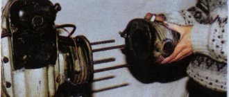
Due to a gross design miscalculation, the crankshaft of the engine of the Izh-Planet (SZD) motorcycle, having traveled some measly 5,000 km, successfully “grunted” (knocked). Even Chinese plasticine goes through many times more, but here is “Planet”. How so? Of course, to clarify the picture, it’s worth making a little reservation: The crankshaft, the repair of which will be discussed in this article, is slightly different in design from the original “planet” one, since it is from the SZD (motorized sidecar) engine. But in essence, there is practically no difference between these shafts and engines. The reason for the rapid failure of the crankshaft was that the bearing of the lower head of the connecting rod, due to a gross design flaw, was not at all lubricated with oil during operation.
In the cheeks of the crankshaft, recesses were made for the lower head of the connecting rod (it is not clear why), so when the lower head of the connecting rod fell into place, the standard oil channels of the lower head of the connecting rod were blocked by the walls of the recess, which led to “oil starvation” of the bearing.
Here, that same depression in the cheek, of unknown purpose. But the oil channel (ordinary chamfer) on the “native” connecting rod, the channel must be said: it was made to “fuck off”, and it’s not a channel in essence, but another Soviet bullshit ( Even the Chinese don’t allow themselves to do this). Through such a channel, lubricant cannot even theoretically flow to the bearing. Now look, if you put a new connecting rod with developed channels for lubrication, then all the same, the channels are blocked by the walls of the recess. Our task for today: Install a new connecting rod, instead of the old one, in the crankshaft, having previously taken care of its normal lubrication. And then, the whole thing must be carefully aligned using special measuring tools. First, the crankshaft must be disassembled.
We are looking for a sheet of metal of suitable thickness (7-8 mm) and using a grinder we cut out a wedge approximately in the middle.
We place the crankshaft on the sheet. We lay the sheet on some powerful beams so that the crankshaft journal hangs freely in the air, take a suitable mandrel, place it on the finger and use a heavy sledgehammer to knock the finger out of the cheek. After removing the finger from one cheek, take the second cheek, place it on the sheet and knock out the finger in the same way. Before removing the finger, remember the main rule: Never try to knock out a worn finger all the way through the second cheek! During engine operation, the working surface of the bearing pin of the lower connecting rod head takes on an elliptical shape, so if you decide to knock out the pin with a worn surface through the cheek, the result will be the same - you will violate the geometry of the hole for the pin in the cheek. Because of this, the new finger will no longer stay in such a hole! Previously, a new connecting rod was purchased from the online store (factory-made, not 100% made in China). We are looking for the thinnest and most worn-out diameter cutting disc for the grinder, prepare a container with water in advance, install the disk on the grinder and proceed to finalizing our connecting rod
We cut a small groove at the bottom of the connecting rod, through which the bearing will be lubricated; you need to saw slowly, a little at a time, while constantly lowering the part into the water; under no circumstances should the bearing be overheated, otherwise all the work will go down the drain.
Such a groove is quite enough to lubricate the bearing; as you can see, due to the timely cooling of the part with water, there are completely no traces of blue. After cutting the groove, we take the files and carefully sand all the burrs, sharp corners, “other jambs” both inside and outside. The connecting rod is modified, now you can start assembling. We lay any cheek on some flat surface (preferably wooden) and Using a mandrel, a heavy hammer or a small sledgehammer, we drive the bearing pin into the cheek. Be careful that your finger does not stick out of your cheek. We put the support washer on the finger, then we put the connecting rod with the pre-washed bearing there and put the second washer on top.
We adjust the mandrel under the finger, take the second cheek, turn it around so that it is as equal as possible to the first and, through a spacer, place the second cheek on the shaft.
You shouldn’t push the cheeks together too much; bring them together so that there is a small gap (0.15-0.2 mm) between the connecting rod and the cheek. The final stage in all this work will be the final alignment of the crankshaft.
The crankshaft cheeks do not always occupy a level position during assembly, which is why the crankshaft journals are in different axes. With such an imbalance along the axes, the engine simply cannot work. Therefore, to begin with, we take a caliper in our hands and measure the thickness of the crankshaft in certain places (marked with arrows).
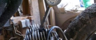
In case of any discrepancies in the thickness of the crankshaft, we either move the cheeks in the desired direction or compress them. Until the thickness of the crankshaft in all places of measurement is absolutely the same. After we have equalized the thickness, we place the crankshaft on the prisms, install the indicator on the stand and proceed to the final one. Rotate the crankshaft so that the indicator arrow shows the maximum beating We take a chalk and put a mark along the axis of the indicator. We take a metal plate, cover it with a sheet of some non-ferrous metal, in our case the role of the non-ferrous metal is played by a piece of lead. And lightly hit (where the mark is) with the marked cheek on the slab. Afterwards, we install the crankshaft on the prisms and check the runout, and repeat this until we can reduce the runout of the axles to the minimum possible value (no more than 0.03 mm).
This work may seem difficult only at first glance, but in fact everything is very easy and simple, the main thing is not to rush! And of course, measuring instruments play a major role here; without them, there is no point in taking on such work.
Why does the gap between the piston and cylinder change?
Car designers strive for engine parts to operate in fluid friction mode.
This is a method of lubricating rubbing surfaces when, due to the strength of the oil film or the supply of oil under pressure and at the required flow rate, direct contact of the parts does not occur even under significant load.
On the subject: How to understand that the cylinder head gasket is broken
This state cannot always be maintained and not in all modes. Several factors influence this:
- oil starvation, the supply of lubricating fluid, as is done in the sliding bearings of the crankshaft and camshaft, under pressure into the area between the piston and cylinder is not carried out, and other lubrication methods do not always give a stable result; special oil nozzles work best, but for various reasons they put them up reluctantly;
- a poorly made or worn honing pattern on the surface of the cylinder, designed to hold the oil film and prevent it from completely disappearing under the force of the piston rings;
- violations of the temperature regime cause the thermal gap to zero, the disappearance of the oil layer and the appearance of scuffing on the pistons and cylinders;
- the use of low-quality oil with deviations in all significant characteristics.
It seems counterintuitive, but the cylinder surface wears more, although it is usually made of cast iron, a solid cast iron block or various dry and wet liners cast into the aluminum of the block.
Even if there is no liner, the surface of the aluminum cylinder is subjected to special treatment, and a layer of a special hard wear-resistant coating is created on it.
This is due to a more stable pressure on the piston, which, in the presence of lubricant, almost does not remove metal from it during movement. But the cylinder is subject to rough operation of spring rings with high specific pressure due to the small contact area.
This is interesting: How to check the camshaft position sensor DPRV
Naturally, the piston also wears out, even if this happens at a slower rate. As a result of the total wear of both friction surfaces, the gap continuously increases, and unevenly.
Photo report: Repair of the engine of the IZH-Planet motorcycle 2, 3, 4 and fifth model
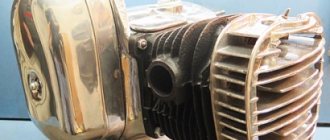
Nowadays it’s rare to find a “Planet” anywhere, especially in stock form. Grandfather's sheds where they once stood in abundance have long been cleaned out by the suffering, and the garbage dumps where they once lay are overgrown with grass... The only place where you can still find something more or less decent is local newspaper advertisements. You can also search on Avito, but before you buy it, look at the product in person, otherwise they will send you a bag of bricks instead of an engine... I was lucky: I found an advertisement in a local newspaper for the sale of an engine from a motorcycle, I went to the place, inspected it, and made an agreement , bought it and brought it home. Don’t let the fact that the engine is from a motorized stroller scare you - the engine is completely identical to the original Planetovsky one.
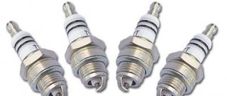
In general, when I tossed the engine around, I was happy and immediately upset... I was happy because the engine was stock and had no signs of interference. There was also original oil and a USSR spark plug. I was upset because the piston and lower connecting rod bearing were killed.
I had a good factory cylinder in stock: bored to repair size + a factory piston, chrome rings and pin were purchased for it a long time ago. I bought the connecting rod in an online store. We managed to find a factory one - not plasticine. I modified it a little: I made a small cut in the lower head to improve bearing lubrication, decompressed the crankshaft, threw out the old connecting rod, installed a new one and then centered the crankshaft using an indicator.
Tools
Tools you will need:
- Drill or screwdriver
- Metal drill 4 - 5 mm
- Flat file
- Technical hair dryer
- Mandrels. Plumbing fittings can be used as mandrels
- Powerful flat head screwdriver
- Open-end or socket wrench 14
- Clamp
- Hammer or mallet
- Oil can or syringe
- Sealant
- into the upper head of the connecting rod
- lower connecting rod head
- into both oil channels of the crank chamber
- If the retaining ring dangles, straighten it or replace it with a new one.
- If the retaining ring is not completely flat, replace it with a new one.
- If the gap is less than 0.3-0.45, sharpen the ring locks with a file
- If the gap is greater than 0.3-0.45, install new rings; if that doesn’t help, bore the cylinder to the repair size
- Crankshaft main bearings 2505k
- Additional crankshaft support bearing 304
- Right oil seal IZH-yu sb. 1-48-3
- Left main oil seal IZH-yu sb. 1-50
Preparation
To carry out high-quality repairs, the engine parts must be clean, the threads in the crankcase must be threaded, the oil seals and gaskets must be new. First, we clean the oil channels in the crank chambers. There are two channels in the Izh-Planet engine: one in the left half of the crankcase, the other in the right. We find the channels and if they are very clogged, we clean them with wire, rinse them with clean gasoline and blow them with compressed air.
Installation of bearings and seals
We install a retaining ring in the left half of the crankcase. Depending on the model of the main oil seal, we install a spacer sleeve in the mounting hole of the main bearing, or, if the oil seal was originally wide (there are some), we heat the crankcase and, on the inside of the crankcase, place the oil seal until it stops retaining ring. My engine had a regular narrow oil seal, so I put a bushing. Using a mandrel, we install the main oil seal in the preheated crankcase. Quickly, before the crankcase cools down, place the oil guide washer on the oil seal. The oil guide washer has a saucer-shaped profile. We place it on the oil seal so that the concave side faces us, and the curved side faces the clutch basket. While the crankcase is still warm, we press the outer race of the main bearing into it using a mandrel.
If you are going to replace the main bearings with new ones, don’t be lazy: find a sheet of iron 7-8 mm thick, cut a wedge in it for the connecting rod, pass the sheet of iron between the cheeks of the crankshaft and use a mandrel to drive the main bearing onto the axle.
This way you will protect yourself from damage to the crankshaft. The main bearing has a very high interference and fits into the axle with a very large force. It is not uncommon for people to simply knock out the axle (the axle on the planetary crankshaft is pressed into the cheek) inside the crankshaft, but they were never able to put the bearing on. Native made in USSR 2505 KM
Installing the crankshaft
Lubricate the edges of the main oil seal and the bearing with clean engine oil. Place the left half of the crankcase on the blocks, take the crankshaft in your hand and turn it into the crankcase. You need to insert the crankshaft very carefully, turning it a little. If you hammer the crankshaft into the crankcase, you will 100% tighten the seal lip!
Assembling the crankcase halves
We degrease the connector of the halves, knock out the guide bushings a little so that they extend 5-6 mm above the plane. Depending on your desire, we assemble the checkpoint. Personally, I assemble the gearbox only after assembling the engine, it’s more convenient for me. We apply any automotive sealant to the connector, install the second half of the crankcase, tap it with a mallet, install the gearbox cover and tighten the crankcase with bolts. We don’t pull the bolts anyhow, but strictly according to Feng Shui : we pull about a third of the force, first crosswise in the middle, then the periphery and gradually increasing the force over several circles, tighten the bolts as much as is sufficient.
Installation of the cylinder-piston group
It is not advisable to remove the gearbox cover until the sealant has dried; there is no need to rush in this matter. It’s better not to rush things and install the cylinder while the sealant dries. Add some engine oil:
To improve lubrication, it is advisable to drill holes in the piston bosses. But you don’t have to drill - it depends on your desire. We install the piston pin retaining ring into the boss. Before installation, it is advisable to bend the locking ring a little and be sure to check how it fits after installation:
We heat the piston with a hairdryer and, using a mandrel, hammer the finger into the piston so that it comes out no more than 5-6 mm. We look for an arrow-shaped mark on the bottom of the piston. We orient the piston with the arrow to the exhaust port of the cylinder (“to the exhaust”), put the piston on onto the connecting rod, hammer in the piston pin and install the second retaining ring. Insert the rings into the cylinder and measure the gap between the locks with a feeler gauge:
To improve the wearability of the rings and reduce noise from engine operation, it is advisable to chamfer the edges of the rings. If you want to bother with the hunt: place the ring on a flat surface and use a file to slightly round the edges. We put the rings on the piston, fill the piston with the rings with oil, install a gasket under the cylinder (preferably with a sealant), tighten the rings with a clamp. We cut the clamp out of tin and from the same tin we bend the bracket with which we will fix it. We put on the cylinder. After the rings go into the cylinder, we unfasten the clamp, lower the cylinder and screw it to the crankcase.
We turn the crankshaft several times and if the piston moves in the cylinder easily and without grinding, lower it down a little, pour a little engine oil into the cylinder, install a new gasket on the cylinder and screw the head on.
We install the additional crankshaft support bearing in its place, place the required number of adjusting washers on top and secure it with a retaining ring. The adjusting washers must ensure axial play of the crankshaft within 0.1 mm. Before installation, sealed bearings must be opened! 304 goes here . On the other side of the crankshaft we install a flange with a main oil seal. Pay attention to the oil channel through which oil flows to the right main bearing of the crankshaft. According to the good old collective farm tradition, this channel is sealed with sealant and the lubrication of the bearing stops. To avoid this trouble, place the flange dry without sealant and everything will be fine.
After the sealant has dried, you can begin adjusting and assembling the gearbox and replacing the clutch basket.
Numbers of bearings and oil seals for the Izh-Planet motorcycle engine 2, 3, 4 and fifth model.
The 2022 motorcycle season is just around the corner, and I have completely abandoned my motorcycle and only thanks to my friend will I start working on my little red dragon again) Photo of what it looked like at the end of the 2016 season.
I'll start with the engine. The engine is still the same, carbs, lx, flywheel in general as it was. BUT finally I replaced the CPG with a better one. Unfortunately, Kawasaki KE175 piston is very difficult to find, and it requires quite a bit of finance. In this regard, I took a completely new piston, bored at the factory, with pistons of the correct geometry and with thin 1mm rings.
I’ll say right away that the dimensions of the piston, the position of the pin, and the length of the skirt remained factory, which means that the ringing will be like this in any case. (who knows the defect of the air Jupe piston will understand).
Otherwise, the pistons are very good, the alloy is of high quality, the rings are thin (lower temperature + longer life). As time has shown, even after the most severe abuse of the engine in the heat and the tachometer in the red zone of the piston, they still stuck to the liner, BUT there are no consequences in the form of molten aluminum on the liner, the only thing in the places of sticking was that the piston changed color to a more matte one. Although cruising at a speed of 90-100 does not heat up the engine to forced stops, which is good news.
In addition to all this, I abandoned the separators and, as Grigoriev said in his book, installed a stacked bearing. As a rule, it is easiest to take needles from the same separators or look for Czech ones. I found 19.5mm needles (stock 17) made in the USSR, which I have had for half a year and are in perfect condition. What it looks like.
In general, I have already tested the piston, I erased the first set of rings (coated cast iron rings). Photo of ring wear + condition of new rings for 2022. Wear:
New:
I decided not to raise the blowing itself, especially the drainage phase, since I had already played enough with it. Issue 173-175, the inlet is sort of permanently purged according to Grigoriev. The plans are not to turn the engine above 7000 rpm, and even at stock it picks up 120 rpm quickly, no more is needed.
In general, everything about the engine, the rest of the modifications are in my other posts.
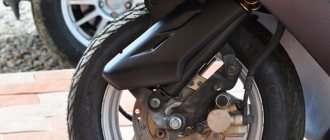
Well, now to the most interesting part, changes to the chassis, namely the front end.
I sold the front end from the PSA and decided to look for a whole front end from the Japanese. There were no ideal options for a small amount, but I came across a rather inexpensive option with a 1989 Kawasaki ZX10.
What it roughly looks like:
The main + of the chassis is, of course, the quality of work, and disc brakes, which are sorely lacking in city mode. Naturally, this is not without problems: 1. The main problem immediately was a broken disk, which in my city cannot be clamped with anything to align it. I had to Improvise it, bend it out in a garage, and then deal with balancing it and the rest.
2. The second problem is adapting the front end to the stock frame. As it turned out, the Japanese steering wheel is much longer and cannot be done without huge alterations. In addition, the installation of tapered bearings cannot be avoided because with such brakes the stock bearings will fly every month. Of course, I had thoughts of cooking and cutting, but I didn’t want to. As a result, they helped me make unusual bearings for my motorcycle.
3. The next problem is the brakes. Actually, I haven’t decided it yet. Unfortunately, the original calipers are not in the best condition, without pads, brackets, piston, they have oxidized and are not working at all. Maybe someone involved in repairs will sell it inexpensively or exchange it for workers with my additional payment.
4. Well, the last problem is the exact calculation of the model and behavior of this fork. It looks identical to the 1989 ZX 10, but mine has a rebound adjuster and the diameter is an issue. According to the manual the ZX is 41mm, but mine is 38mm. In this regard, I cannot accurately determine the volume of oil that needs to be filled.
In general, that’s all for now, special thanks to my friend Vovchik, for whose sake I took up my motorcycle again for joint trips to rallies with his IZH Jupiter 5,400cc, but that’s a completely different story;)
Assembly and disassembly of the IZH Planet 5 engine
Domestic motorcycles of the IZH brand, despite their age, are still popular in various parts of our country. This simple and unpretentious transport is especially popular among residents of rural areas. Not every imported motorcycle can start at +40 or -30, run on any gasoline, and when modified with a sidecar, it turns into a universal transport for a hunter or fisherman. Unfortunately, these motorcycles also have a significant drawback - low engine life. It’s rare that an IZh can work for several seasons and not fail. That is why below you will find step-by-step instructions on how to disassemble and reassemble the IZH Planet 5 engine.
Repairing the IZH Planet engine can be done entirely with your own hands, since the simple design allows this. The main postulate of such work is to follow the established order of disassembly and assembly.
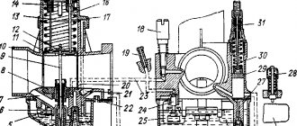
Following the diagram below, you can get to all engine elements in order to inspect or replace them. It makes sense to completely disassemble the engine if you need to get to the crankshaft or left oil seal. Failure of the latter leads to a decrease in driving characteristics and smoking due to the presence of a large amount of oil inside the crank chamber.
Step-by-step disassembly diagram:
Engine disassembly is complete, now you can repair the IZH Planet 5 engine.
Engine assembly IZH Planet 5
The engine assembly process occurs in the reverse order, with the obligatory condition that all technological features of the process are observed. When restoring the motor, do not forget that this is a precise mechanism and its main characteristics will depend on how carefully you approach the fitting and installation of all parts.
- All dismantled spare parts and engine elements are washed with solvent and an inspection is carried out. If serious chips, scuffs or other defects are found, these parts are replaced. If the left half of the crankcase or the right is damaged, then they are replaced in pairs.
- The joining surfaces are cleaned of traces of sealant or gaskets.
- The elements of the gear shift assembly are polished to a shiny surface.
- We fill the left oil seal with grease and install it in place with the bearing ring, followed by a shaped washer.
- We install the retaining ring, after checking the accuracy of installation, proceed to the next steps.
- Next we mount the main bearing rollers and lubricate them.
- We put on the crankshaft and place a ball bearing lubricated with grease on it.
- We install spacer washers and follow them with a retaining ring.
- Let's see how easily the crankshaft rotates after lubricating it with engine oil.
If assembly at this stage does not cause any complaints, the following steps correspond to the reverse order of engine assembly. Please note that you need to purchase a complete set of new gaskets, and additionally lubricate the connecting surfaces with heat-resistant sealant.
Engine IZH Planet 3, 4 and 5, disassembly, assembly for repair and tuning
When disassembling the engine, you must first drain the oil from it and remove it from the motorcycle frame; you must wash the engine thoroughly. To do this, it is advisable to use a high-pressure apparatus (car wash) with car shampoo. Having washed the engine and protected it from getting dirt inside, we proceed to disassembly.
We remove the right engine cover, remove the generator (by unscrewing the mounting bolts). Be careful not to damage the paronite gasket; remove the cover and disassemble the box. We take out the gears with the shafts and disassemble the shift mechanism, remove the control levers from the engine, and remove the clutch cover. We completely disassemble the clutch and remove the motor chain. We disassemble the piston, remove the cylinder head (by unscrewing the fastening nuts), then remove the cylinder. After this, remove the piston from the crankshaft, having previously removed the retaining rings and carefully knock out the piston pin. We place the engine on its left side and carefully, without damaging the heads, unscrew the connection bolts, using a powerful screwdriver. Then we knock out the centering halves of the crankcase half the length of the bushing.
Using a mallet, we strike the area where the crankcase halves are separated. We remove the crankcase half from the crankshaft and press the bearings out of it. To improve the pressing of the bearing, oil seal and outer race of the roller bearing from the crankcase, the crankcase half must be heated to 70-90 degrees.
Disassembled parts must be washed in gasoline and carefully inspected; damaged and faulty parts must be replaced with new ones. Clean the junction of the crankcase halves from old glue. On the oil seals (cuffs), pay attention to cracks and springs. The bearings should rotate easily without jamming and should not have any play. Having prepared serviceable parts, we begin assembly. We assemble the engine in the opposite order of disassembly. Be sure to heat the crankcase half to the same temperature, which makes assembly easier and preserves the crankcase surface from damage during pressing. The connection of the crankcase halves must be coated with BF-4 glue. When installing the piston on the crankshaft, it is advisable to heat it to a temperature of 60 degrees, this will help when inserting the piston pin. During assembly, you also need to lubricate the cylinder mirror and piston pin with engine oil.
When installing the cylinder and cylinder head, install new gaskets. Pay attention to the position of the piston rings in the piston locks; if installed incorrectly during assembly, the rings may break.
Motorcycle Izh Planet 5 engine specifications
Two-wheeled motorcycle IZH Planet 5 engine, which developed only 22 hp. pp., throughout almost the entire period of its production, and from 1987 to 2008 it was considered one of the most common middle-class motorcycles among domestic buyers.
- Engine for the fifth model.
- Reasons for repair.
- Engine modernization.
This motorcycle was developed and manufactured at the Izhevsk Machine-Building Plant (Izhmash), which is located in the capital of the Republic of Udmurtia. The main advantages that ensured the popularity of Izhevsk motorcycles, and not only in Russia, should be considered:
In addition, Izhmash constantly sought to make changes and improvements in the design of its products, including the Izh Planet 5 motorcycle model and the Izh Planet 5 engine. At the plant itself, production was regularly modernized in order to improve quality. Thus, the assembly of power units, including the assembly of the IZH Planet 5 engine, was carried out at a specialized technological site.
Engine for the fifth model
The Izh Planet 5 engine contains the following main characteristics and indicators:
- execution type – two-stroke with one cylinder;
- working volume – 345 cubic meters. cm;
- piston diameter – 72 mm;
- power – 22.0 l. With. at 4800 crankshaft rpm;
- battery voltage – 12 volts;
- cooling option – air;
- ignition type – contactless;
- the ratio of the mixture of oil and gasoline (A 76) is 1/30.
Reasons for repair
Complete disassembly of the Izh Planet 5 engine during repair work is carried out if damage or breakdown of the following elements occurs:
- crankshaft;
- bearings;
- piston;
- connecting rod
Failure of these parts can occur due to engine jamming, general severe wear, which is accompanied by increased noise during operation, as well as various knocking noises in the crankcase. In addition, repair of the Izh Planet engine with its complete disassembly is carried out when the crankshaft seals are worn out. At the initial stage of production of power units, the reed valve on the Izh Planet 5 had certain technological shortcomings associated with low strength. Therefore, it quickly collapsed, its elements fell inside the cylinder, which required further disassembly and, in most cases, replacement of the Izh Planet 5 piston.
After a certain time, the manufacturer eliminated this defect.
If, when operating the engine, all routine and technical maintenance procedures established by the manufacturer were observed, and appropriate technological materials and fluids were used, then it was operated for a long time, while maintaining its technical parameters.
Engine modernization
The design features of the IZH Planet 5 motorcycle are that the owner, having certain technical skills, could do tuning work with his own hands to give his motorcycle a more modern look and increase its power. Tuning the IZH Planet 5 engine was aimed at increasing its power. Such work usually began with repressing the crankshaft of the IZH Planet 5 engine, which made it possible to increase its power by 10-15%. The next step to increase power was boring the cylinder to a repair size of 76 mm and modifying the piston group. In some cases, a piston group from an IZH Sport motorcycle was installed.
The next step was to change the basic clutch since it could not work with a more powerful engine. For this purpose, the clutch was disassembled and the standard discs were replaced with thicker metal ones. This increased the heel area, which correspondingly reduced slippage during shifts.
For more charged versions, turbocharging was used on the engines of IZH Planet 5 motorcycles. But, no matter how well the work on modifying the IZH Planet 5 engine is carried out on your own, this still leads to a decrease in service life and an increase in the number of repairs.
Compliance standards
In its initial state, the cylinder fully corresponds to its name; it is a geometric figure with a constant diameter along the entire height and a circle in any section perpendicular to the axis. However, the piston has a much more complex shape, and it also has heat-setting inserts, as a result of which it expands unevenly during operation.
To assess the state of the gap, the difference between the diameters of the piston in the skirt area and the cylinder in its middle part is selected.
Formally, it is generally accepted that the thermal gap should be approximately 3 to 5 hundredths of a millimeter in diameter for new parts, and its maximum value as a result of wear should not exceed 15 hundredths, that is, 0.15 mm.
Of course, these are some average values; there are a great variety of engines and they differ both in different approaches to design and in the geometric dimensions of parts, depending on the working volume.