CDI electronic ignition The
CDI electronic ignition system is not that complicated and is easy to diagnose if you understand how it works. The CDI ignition (Capacitor Discharge Ignition) consists of several main components (in the diagram):
C—chargeable capacitor; D - rectifier diode; SCR - switching thyristor; T - ignition coil.
There are many variations of this scheme, let's look at the principle of operation. Capacitor C is charged in turn by rectifier diode D, and then discharged through the SCR thyristor to step-up transformer T. At the output of the transformer we receive a voltage of several kilovolts, due to which a breakdown of the air space between the electrodes in the spark plug occurs. This is all! It's that simple!
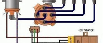
But making the entire mechanism on the engine work is much more difficult. The classic CDI ignition circuit is a two-coil design, first used on Babette mopeds. One coil is a charging coil (high voltage), the second (low voltage) is a thyristor control sensor. Both coils are connected to ground with one wire. We connect the output of the charging coil to input 1, and the sensor to input 2. The spark plug is connected to output 3.
A circuit assembled using modern components begins to produce a spark when input 1 reaches approximately 80 Volts; the optimal voltage is considered to be about 250 Volts.
History of creation
The operating principle of this system is based on the use of a capacitor discharge. Unlike the contact system, CDI ignition does not use the interrupter principle. Despite this, contact electronics have a capacitor, the main task of which is to eliminate interference and increase the intensity of spark formation at the contacts.
Individual elements of the CDI ignition system are designed to store electricity. Such devices were first created more than fifty years ago. In the 70s, rotary piston engines began to be equipped with powerful capacitors and installed on vehicles. This type of ignition is in many ways similar to electricity storage systems, but it also has its own characteristics.
How to connect a switch on a scooter? General recommendations
A huge number of 4t scooters are offered in Russia. Low-quality switches are installed in budget-class models, which tend to burn out under the influence of increased load or moisture. This issue may also affect owners of more expensive equipment, because with the help of switches, manufacturers limit the maximum speed of movement. Before performing any work, you should carefully familiarize yourself with the electronic features of your vehicle. This will save a lot of money on contacting specialized professionals and will make the procedure as fast and comfortable as possible.
Advantages of the CDI system
Capacitor ignition also has its advantages, including a steep front of high-voltage pulses. This characteristic is especially important in cases where CDI ignition is installed on IZH and other brands of domestic motorcycles. The spark plugs of such vehicles are often filled with large amounts of fuel due to incorrectly configured carburetors.
For the operation of thyristor ignition, the use of additional sources generating current is not required. Such sources, such as a battery, are only required to start the motorcycle using a kick starter or electric starter.
The CDI ignition system is quite popular and is often installed on scooters, chainsaws and motorcycles of foreign brands. It was almost never used in the domestic motorcycle industry. Despite this, you can find CDI ignition on Java, GAZ and ZIL cars.
Simulation stand
If you do not have a second scooter, and also do not have access to it, then you should think about purchasing or making a special stand for yourself that would simulate the operation of your scooter. It is ideal for testing the switch on a Honda scooter, as well as on any other model, and if you regularly use such a vehicle, then the likelihood is that you will have to use the stand more than once or twice, so it is definitely worth the investment into it.
Now it is much more convenient to purchase it and install it in your garage, so that, if necessary, you can always check any part without using another scooter. But you can also do it yourself - only in this case you need to have very high skills and abilities in engineering, and it is also advisable to have impressive experience with such equipment. You should also know that such a stand has other advantages over a second scooter for control.
Operating principle of electronic ignition
Diagnostics of the CDI ignition system is very simple, as is the principle of its operation. It consists of several main parts:
- Rectifier diode.
- Chargeable capacitor.
- Ignition coil.
- Switching thyristor.
System layout may vary. The operating principle is based on charging a capacitor through a rectifying diode and then discharging it to a step-up transformer using a thyristor. A voltage of several kilovolts is generated at the output of the transformer, which leads to air space between the spark plug electrodes.
The entire mechanism installed on the engine is somewhat more difficult to make work in practice. The dual-coil CDI ignition design is a classic design that was first used on Babette mopeds. One of the coils - low voltage - is responsible for controlling the thyristor, the second, high voltage, is charging. Using one wire, both coils are connected to ground. The output of the charging coil is supplied to input 1, and the output of the thyristor sensor is supplied to input 2. The spark plugs are connected to output 3.
A spark is supplied by modern systems when it reaches about 80 volts at input 1, while the optimal voltage is considered to be 250 volts.
Buying a switch
Purchasing a switch is the easiest and fastest way out, since you do not waste time, effort, and the cost of this mechanism is not so high as to save much on it. This is really the most reasonable solution that you can come up with in a situation where your switch has burned out
However, again, it is very important that you check everything correctly, do not use only a tester, but carry out a full procedure for checking the switch so that you can say with certainty that this is the reason. Otherwise, you will just spend money on a new part, but your scooter will still not function
Types of CDI scheme
A Hall sensor, coil or optocoupler can be used as thyristor ignition sensors. For example, Suzuki scooters use a CDI circuit with a minimum number of elements: the opening of the thyristor in it is carried out by the second half-wave of voltage removed from the charging coil, while the first half-wave charges the capacitor through the diode.
The engine-mounted chopper ignition does not come with a coil that can be used as a charging coil. In most cases, step-up transformers are installed on such motors, which raise the voltage of the low-voltage coil to the required level.
Model aircraft engines are not equipped with a magnet-rotor, since maximum savings in both dimensions and weight of the unit are required. Often a small magnet is attached to the motor shaft, and a Hall sensor is placed next to it. A voltage converter that increases the 3-9V battery to 250V charges the capacitor.
Removing both half-waves from the coil is only possible when using a diode bridge instead of a diode. Accordingly, this will increase the capacitance of the capacitor, which will lead to an increase in the spark.
Design
The CDI electronic ignition consists of various parts, among which there is always a voltage converter, the action of which is aimed at charging the storage capacitors, the storage capacitors themselves, the electric switch and the coil. Both transistors and thyristors can be used as an electric switch.
Setting the ignition timing
The ignition is adjusted in order to obtain a spark at a certain point in time. In the case of fixed stator coils, the magnet-rotor rotates to the required position relative to the crankshaft journal. The keyways are sawn through in those patterns where the rotor is attached to the key.
In systems with sensors, their position is adjusted.
The ignition timing is given in the engine reference data. The most accurate way to determine SOP is to use a car strobe light. Sparking occurs at a certain position of the rotor, which is marked on the stator and rotor. A wire with a clamp from the switched on strobe is attached to the high-voltage wire of the ignition coil. After this, the engine starts and the marks are illuminated with a strobe light. The position of the sensor changes until all marks coincide with each other.
Problems when paying with bank cards
Sometimes difficulties may arise when paying with Visa/MasterCard bank cards. The most common of them:
- There is a restriction on the card for paying for online purchases
- A plastic card is not intended for making payments online.
- The plastic card is not activated for making payments online.
- There are not enough funds on the plastic card.
In order to solve these problems, you need to call or write to the technical support of the bank where you are served. Bank specialists will help you resolve them and make payments.
That's basically it. The entire process of paying for a book in PDF format on car repair on our website takes 1-2 minutes.
If you still have any questions, you can ask them using the feedback form, or write us an email at [email protected]
Ignition system diagnostics
Checking the serviceability of the CDI system is a fairly simple procedure that every car or motorcycle owner can handle. The entire diagnostic procedure consists of measuring the voltage supplied to the power coil, checking the ground connected to the motor, coil and switch, and checking the integrity of the wiring supplying current to consumers of the system.
The appearance of a spark on the engine spark plug directly depends on whether the coil receives power from the switch or not. No electrical consumer can operate without proper power. Depending on the result obtained, the check either continues or ends.
The main differences between switches
Products from Chinese manufacturers, as a rule, use one of two types of switches - DC or AC. The physical feature of the former is that it is much larger in size. The principle of energy accumulation for spark transmission also has a different nature. In DC, a rechargeable battery is used to store the spark (the switch is powered directly from a 12 Volt battery). In the case of AC type switches, this energy is supplied through the use of one generator coil (the switch is powered by a ~ 160 Volt coil). This is where the differences between the presented varieties end.
Results
- The absence of a spark when power is supplied to the coil requires checking the high-voltage circuit and ground.
- If the high-voltage circuit and ground are fully operational, then the problem is most likely with the coil itself.
- If there is no voltage at the coil terminals, measurements are taken on the switch.
- If there is voltage at the switch terminals and there is no voltage at the coil terminals, the reason is most likely that there is no ground on the coil or the wire connecting the coil and the switch is broken - the break must be found and repaired.
- The absence of voltage on the switch indicates a malfunction of the generator, the switch itself, or the induction sensor of the generator.
The method for checking the CDI ignition system coil can be used not only for motorcycles, but also for any other vehicles. The diagnostic process is simple and consists of a step-by-step check of all parts of the ignition system to determine the specific causes of problems. Finding them is quite simple if you have the necessary knowledge about the structure and operating principle of the CDI ignition.
DIY CDI block for Fisher 2.5 outboard motor
It is unlikely that this article will be useful or interesting to most users of the Fish Hook resource. There are not many on the website of owners of these motors. But, judging by the messages that come to me in personal quantities, and by email views of my previous articles on this topic, it is clear that the topic of repairing and maintaining their boat fishing assistants is of quite interest to many. The article “Manual for maintenance and repair of the Fisher 2.5 outboard motor” (fish-arti.ru/hook. hnogo-501/) alone has about 20 thousand. That means. Views, and this article may be useful to someone.
A well-known proverb says: “Prepare a sleigh in the summer, and a cart in the winter.” Now is the time for winter to start preparing my outboard motor for the next season, which suffered an unfortunate breakdown at the end of the summer. I have already eliminated the cause of the breakdown, but now I’ll tell you how to do it first. But, I did, a little background.
I got this motor back in 2013. And during all this time he never let me down on the water. It didn’t act up and didn’t break (except for the cut dowels, but how about that). It always started well, first on almost a try.
November 2013 R. Kumylga. fishing First with a motor, and first run-in.
The engine worked perfectly and almost the entire boat failed. It’s not the season and he’s on a multi-day trip when rafting along the river. And at the end of the summer, Khopru began to act up.
My wife and I were going to go fishing and relax on the beautiful river Plana. The Ursa were quite interesting: we planned to take the boat up a few kilometers above the rift, then go down to the confluence of the Ursa and return, and the Don back.
August 2016 R. Bear.
From our departure from the camp, we overcame the riffle, climbed up the beach to the motor and began to drift. Having rafted to the parking lot, we decided to repeat the swim: we had time, and many were very beautiful, and there was fishing.
But in an interesting attempt to climb upstream again, the engine, which had been working normally before, suddenly stalled. Attempts to start it did not lead to success. What to do? It was necessary to find the cause and, if possible, eliminate it.
We rafted to our mooring and parking lot. Olga went to cover the little one, and I started cleaning the clearing with the motor. On the last fishing trip, on this same motor trip, there was also a little trouble with the river. too, it then suddenly stalled, but the reason was discovered during: while quickly servicing the motor, I inadvertently pushed the connector coming from the switch onto the vibration coil loosely. From the ignition it jumped out of the terminal. It was my fault, and I quickly eliminated the fault.
Gidrik.ru - Club of lovers of jet skis and other equipment for active recreation
| Current time: 19 Sep 2022, 17:47 |
CDI ignition.
I'll write a short sketch on ignition. ——————- EVERYTHING WRITTEN FOLLOWING APPLIES TO 2T ENGINES ——————- (there have been a lot of questions on the forum lately, the “no spark” type, understanding how this type of ignition works can greatly facilitate troubleshooting)
CDI - CAPACITOR DISCHARCH IGNISHON. those ignition with capacitor discharge. In Soviet times, also known as a thyristor ignition system.
Almost all (known to me) 2T engines, in stock, have this type of ignition installed.
The principle of its operation: a pre-charged capacitor is discharged to the ignition coil, a high voltage pulse appears in the secondary winding of the coil, which is supplied to the spark plug. The capacitor is discharged at the right moment by means of a thyristor (controlled semiconductor valve), which is controlled from the driver. The shaper is not just an amplifier that amplifies the signal from the ignition sensor, but is a rather complex device that also performs the function of changing the ignition timing, depending on the speed. therefore, in relation to jet skis we are talking about digital CDI, either DCDI or CDI-D. The capacitor can be charged in several ways (in relation to hydraulics): 1) using a charging coil, such as on the ROTAX 717. 2) using an electronic converter that converts the 12V on-board voltage into a relatively high charging voltage, such as on the ROTAX 787. —— on ROTAX 717, the charging coil, is also an ignition sensor. Those. First, the condenser is charged, then, by changing the polarity on the charging coil (when changing the magnetic poles), a pulse is formed to control the thyristor and, accordingly, a spark occurs.