The switch is an electronic component to ensure the operation of a contactless ignition system. It is transitional between contact and microprocessor. The latter, the most advanced, allows you to control the torque using data read from sensors - oxygen, speed, engine speed and others. But there are still many cars on the roads that have both contact breakers and contactless ones. Therefore, for maintenance and diagnostics, you need to know the purpose of all elements, as well as troubleshooting methods and their main symptoms. Before testing the switch, review all parts carefully.
Contactless ignition system
In total, there are three huge groups of systems - contact, contactless, microprocessor. The first is divided into two subgroups - contact and using a transistor operating in switch mode. Transistors are also used in the design of a contactless ignition system. This scheme began to be actively used in the early 80s of the last century. And it has a number of advantages, which will be discussed below. The switch circuit is simple; it can be implemented both on transistors and on a controller.
But the contactless ignition system also has many disadvantages when compared with a microprocessor one. The latter allows you to control almost all engine parameters. BSZ does not allow this; it also cannot be used normally on injection engines. The reason for the obsolescence of the contactless system lies not only in the development of electronics and the automotive industry, but also in the adoption of stringent measures to ensure the environmental friendliness of internal combustion engines. Unfortunately, only microprocessor control can reduce the amount of harmful substances in the exhaust.
Briefly about the principle of operation
The principle of operation of the ignition sensor is based on the Hall effect, which received its name in honor of the American physicist who discovered this phenomenon in 1879. By applying a constant voltage to the edges of a rectangular plate (A and B in Fig. 1) and placing it in a magnetic field, Edwin Hall discovered a potential difference at the other two edges (C and D).
Fig.1. Demonstration of the Hall effect
In accordance with the laws of electrodynamics, the Lorentz force acts on charge carriers, which leads to a potential difference. The Hall voltage value is quite small, ranging from 10 µV to 100 mV, it depends on both the current strength and the electromagnetic field strength.
Until the middle of the last century, the discovery did not find serious technical application until the production of semiconductor elements based on silicon, ultra-pure germanium, indium arsenide, etc., with the necessary properties, was established. This has opened up opportunities for the production of small-sized sensors that can measure both field strength and current flowing through a conductor.
Main elements of the system
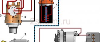
Of course, the first thing to mention is the spark plugs. They are installed in the cylinder head, the electrodes come out from the inside. These are the elements that allow the air-fuel mixture to ignite. But with the help of spark plugs alone, the engine will not be able to run. It is necessary to monitor the position of the crankshaft in order to know in what position the pistons are in the cylinders.
For this purpose, an inductive sensor operating on the Hall effect is used. It is part of the design of another element - the ignition distributor. The sensor produces a pulse that is sent to the switch. This device allows you to amplify a weak signal to a voltage of 12 volts, and then apply it to a coil. A coil is nothing more than a simple transformer (step-up). Its secondary winding has a greater number of turns than the primary. Due to this, the voltage increases and the current decreases. The voltage in the BSZ is supplied to the spark plugs at a value of 30-35 kV (depending on the car model).
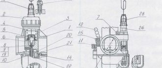
High voltage magneto
Starting engines installed on diesel engines have an autonomous high-voltage source - a magneto, which generates a low-voltage current, converts it into a high-voltage current and supplies it at a certain moment to the spark plugs.
The main magneto malfunctions are:
- rotor demagnetization
- damage to transformer windings
- breaker contact wear
- crack in parts of current-carrying devices
- capacitor breakdown
- violation of the magneto contour angle
The magnetization of the rotor is checked with an MD-4 magnetometer. If it is below 220 μWb, then the rotor is magnetized on the NA-5-VIM device from a 12-volt battery by turning on the device 2-3 times for 1-2 s.
The performance of the transformer is checked on the KI-968 stand with a current of 1.5-2.5 A, which is passed through its primary winding and the stand breaker. At a rotation speed of the breaker cam shaft of 500 min-1, a stable blue spark should appear on the three-electrode spark gap of the stand. The faulty transformer is replaced.
When the magneto is assembled, the rotor should rotate smoothly by hand and self-align into the neutral position, being moved away from it at an angle of 15-20°. Longitudinal movement of the rotor is allowed up to 0.06 mm. The gap between the open contacts of the breaker should be within 0.25-0.35 mm. The spring pressure at the moment of opening the contacts is 5-7 N. The outline is checked on the assembled magneto - the angle between the neutral position of the rotor (the rotor magnets are in a vertical plane) and the position of the rotor when there is a maximum current in the primary winding of the transformer; at this moment the breaker contacts should open. The outline size should be 8-12°. Violation of the outline setting leads to a decrease or complete cessation of sparking due to a decrease in the current in the primary winding of the transformer and the voltage in the secondary. To check the magnitude of the magneto outline, install it on the KI-968 stand, connect it to the drive, set the rotor to the neutral position, and rotate the arrester pointer to zero. Smoothly turning the magneto drive by hand in the direction of operating rotation, record the moment of opening of the breaker contacts (use the stand's IUC device or a test lamp). The outline is determined using the spark gap scale. Set the outline by turning the cam on the rotor neck.
The assembled magneto is tested for uninterrupted spark formation at a rotation speed of 2000-4500 min-1 for 5 minutes with a gap of 7 mm on the spark gap. The high-voltage insulation of the magneto is checked at a rotation speed of 2400-3000 min-1 and a gap on the spark gap of 9-11 mm for 15 s. During the test, sparking must be uninterrupted.
How is BSZ better than contact?
Having carefully read the previous section, you can see that the system uses an inductive non-contact Hall sensor. The advantage is obvious - there is no friction and commutation. For comparison, look at the contact system. In it, the breaker switches the voltage, the value of which is 12 Volts. Whatever one may say, the metal contacts are constantly in contact with each other, gradually wear out, and become covered with soot.
For these reasons, it is necessary to constantly monitor the breaker, adjust the gap, and carry out timely replacement. BSZ is devoid of these shortcomings, therefore, without third-party intervention, the system operates much longer. The Hall sensor fails very rarely, as does the switch. This increases the reliability of the system, but precautions must also be taken, in particular, the connection of the switch to the body must be as tight as possible to ensure effective heat exchange. In addition, BSZ allows you to improve engine performance, increase, albeit slightly, its power, along with increasing reliability.
What is port recycling?
Network communication channel utilization is the percentage of time during which a communication channel transmits signals, or otherwise, the proportion of communication channel capacity occupied by frames, collisions and interference.
Interesting materials:
What should be included in the conclusion of the project? What should a court decision contain? What do beneficial bacteria eat? What is in the lithosphere? What's in Vegas? What kind of Viber program is this? What develops during adolescence? What is the penalty for using other people's photographs? What was one of the reasons for the defeat of whites in the Civil War? What is fard in prayer?
How does a switch work?
Essentially, a switch is a simple signal amplifier. It can even be compared to a Darlington assembly, which is used in microcontroller technology to convert a weak signal from an output port to the required level. The basis of this assembly is field-effect transistors operating in switch mode. An operating voltage is applied to them, a signal is sent to the control terminal, which is amplified and removed from the collector.
The ignition switch has an almost similar operating scheme. Only the signal from the Hall sensor is used. It has three outputs - control, common, plus power. When a metal plate appears in the sensor area, a current is generated, which is supplied to the input of the switch. Next, the signal is amplified and supplied to the primary winding of the coil. The entire system is powered only after the ignition is turned on (after turning the key).
Basic Switch Elements
The switch circuit is quite simple, but making this unit yourself is pointless, since buying a ready-made version will be much easier. Installation must be carried out as competently as possible, otherwise the device will not operate correctly. In addition, when using transistors, you need to carefully select them according to their parameters, and for this you need to have high-quality measuring equipment. Unfortunately, for two identical semiconductors, the spread of characteristics can be very large. And this affects the operation of the device.
Connecting the switch
Cases vary, and it is possible that you will have to change the wiring. Therefore, you will need to take into account the purpose of all pins on the switch plug. This will allow the connection to be made correctly, and there will be no risk of damaging it. The first pin of the switch is the output. In other words, the amplified signal is removed from it. It must be connected to the terminal of the “K” coil. The second contact is connected to ground - the negative of the battery.
All three wires from the Hall sensor go to the VAZ switch. Moreover, the signal wire is connected to the sixth terminal of the switch. The fifth is the power output (the voltage on it is stable 12 Volts). The third output of the switch is ground (minus power). The third is connected inside the block to the second. But between the fourth, which is supplied with power from the battery, and the fifth there is a constant resistance and a voltage stabilizer.
How to check
There is nothing complicated in this procedure. The easiest way is to use a known-good node, since you can check the switch this way in literally a matter of minutes. But if there is none, and you need to determine exactly whether the fault is in the coil or in the switch, it is wiser to use other methods. You will need a simple incandescent lamp. If you don’t know where to get it, then unscrew it from the interior lamp or from the side lights.
Connect one terminal of the lamp to the negative of the battery. Connect the second one to pin “1” of the switch. This is the same pin from which the amplified signal is removed. If the lamp lights up, then the device is working properly. A more advanced testing method is carried out using an oscilloscope. On the screen you can see the magnitude and shape of the signal, and also compare it with the reference one.
what to do if the brain (switch) of a motorcycle burns out / Blog named after. gorini4 / BikePost
Hello, Baykpostovchanin. It seems you are using AdBlock. BikePost develops and exists due to advertising revenues. Add us to the exceptions.
open letter how to disable
Blog named after gorini4
3743rd place in the rating of bikeposts and so many people have such a situation that the motorcycle loses a spark somewhere or the spark disappears on one ignition coil. After a full examination, it turns out that the brains (switch) are dead, and since for some motorcycles the brains are extremely expensive I set out to try to restore those same burnt brains. Let me explain: a common cause of brain death is: 1. Overcharging of the generator. 2. Accidentally lost contact at the battery terminals while the engine is running. (ALWAYS CHECK THE BATTERY TERMINALS FOR THE PRESENCE OF OXIDES AND FOR TIGHTENING OF THE TERMINALS. Because this little thing can cost the life of the brains of your motorcycle) More often, and especially in motorcycles since 1990, protection against overvoltage or internal short circuit began to appear in switches (they especially like to make a short circuit capacitors are shorted) and when this protection is triggered, everyone thinks that the switch has suddenly died and simply throws it away, replacing it with a new one. the brain can be easily restored if everything in it burns out except the processor. (if the processor burns out, you just can’t buy it anywhere as a part) if anyone needs help with repairing the brains of the moto, please contact me, I’ll help as much as I can, I’m not attaching photos of the repaired brains because I simply don’t have these photos.
There is also a case when the brains of a motorcycle can be completely replaced with homemade ones (I personally did it myself), this is especially true for motorcycles of the 80s when original brains are very difficult to find, and if you do find them, they will be very expensive.
Ignition settings
When setting up the ignition, you will need to do the most important thing - install the shafts according to the marks so that the gas distribution functions synchronously with the operation of the piston group. This is the first thing you should do before you start adjusting the ignition. It is worth noting that there should not be any particular difficulties during setup, especially on VAZ 2108-21099 cars. The thing is that the ignition distributor on the engines of these machines can only be installed in one position. Moreover, the ignition switch does not undergo any settings during this procedure, since it does not have any.
The distributor body rotates around its axis to make more precise adjustments. And this turns out to be enough. To accurately set the torque, you can use a simple circuit that uses a simple LED as an indicator. The Hall sensor is disconnected from the system, and positive power is supplied to its negative terminal. An LED is switched on between “+” and the signal LED, and a 2 kOhm resistance is connected in series with it to reduce the voltage. But the plus of the Hall sensor is connected to ground. Now all that remains is to slowly rotate the distributor housing. The moment when the diode lights up will be the desired one.
conclusions
Many advantages are provided by such a simple unit in a contactless ignition system as a switch. This includes an increase in power, even if only slightly, a reduction in fuel consumption, and a significant improvement in the engine in terms of reliability. And most importantly, there is no need for constant monitoring and timely adjustment of the system. The modern driver does not want to repair a car, he needs a means of transportation. Moreover, it is reliable and will not let you down at the most crucial moment. Regardless of which switch is used in the BSZ, its efficiency is much higher than that of a contact breaker.
- How to check the switch yourself?
- 1. Signs of a faulty switch
- 2. Algorithm of actions for checking the switch
- 3. Materials for testing the switch
Among the variety of car parts, there are many elements on the serviceability of which the normal operation of the power unit depends. One of them is the well-known switch, which is an integral part of electrical equipment. Its main purpose is to ensure the normal functioning of the contactless ignition system, so if the element breaks down, problems with starting the engine cannot be avoided. In most situations, this unit is reliable and wear-resistant, but sometimes troubles happen with it.
Simulation stand
If you do not have a second scooter, and also do not have access to it, then you should think about purchasing or making a special stand for yourself that would simulate the operation of your scooter. It is ideal for testing the switch on a Honda scooter, as well as on any other model, and if you regularly use such a vehicle, then the likelihood is that you will have to use the stand more than once or twice, so it is definitely worth the investment into it.
Now it is much more convenient to purchase it and install it in your garage, so that, if necessary, you can always check any part without using another scooter. But you can also do it yourself - only in this case you need to have very high skills and abilities in engineering, and it is also advisable to have impressive experience with such equipment. You should also know that such a stand has other advantages over a second scooter for control.