01/18/2022 13,572 VAZ 2109
Author: Ivan Baranov
Modern cars are mostly equipped with an internal combustion engine. In order to cope with various unforeseen situations on the road, you need to know the structure of the machine. The article describes the operating procedure of the VAZ 2109 cylinders, as well as possible malfunctions in the operation of the power unit.
[Hide]
The operating order of the VAZ 2109 cylinders
Quite often, car owners ask the question why they need to know the operating order of the VAZ 2109 cylinders if the car is working normally.
The fact is that knowledge of the operating principle of the internal combustion engine (ICE) is necessary in order to detect the problem in time and take measures to eliminate the malfunction. Timely measures taken will protect the engine from serious damage. The VAZ 2109 uses a 4-cylinder engine. There are four strokes in engine operation:
1. “Intake”, in this stroke, fuel is supplied to the system, which is mixed with air. At this stage, the cylinder is filled with the working mixture. 2. "Compression". At this stage, the working mixture is compressed due to the movement of the piston in the cylinder. 3. "Expansion". The compressed air-fuel mixture is ignited by a spark generated by the spark plug. As a result of combustion of the mixture, the resulting gases expand and, under high pressure, push the piston down, this movement is transmitted to the crankshaft. 4. "Release". At this stage, through the open exhaust valves, exhaust gases enter the vehicle's exhaust system.
To ensure smooth engine operation, various operating patterns are used to determine the sequence of cylinder operation. The most common scheme is 1-3-4-2; it is this combination that is used in the VAZ 2109. The numbers correspond to the accepted numbering of the cylinders, in which the front part of the engine is usually used as the reference point.
Thus, the working cycle of the VAZ 2109 internal combustion engine is represented by the following sequential actions:
1. In the 1st cylinder there is a downward movement, a working stroke, that is, combustion of the working mixture and expansion of gases. 2. “Compression” occurs in the 3rd cylinder, the piston moves up. 3. In the 4th cylinder there is an “intake”, the piston moves down, and the working mixture is pumped into the cavity. 4. “Exhaust” is carried out in the 2nd cylinder; exhaust gases leave the cavity through the exhaust valves.
Now let's look at several cases of malfunctions in the operation of the VAZ 2109 engine. In order to find out the cause of the breakdown, you should use the following algorithm of actions:
• Start the engine and go to idle speed. Listen to the sounds of exhaust. If uniform, periodic popping noises are observed, then most likely the cylinder is not working due to suction, a faulty spark plug, reduced compression or lack of spark. • Inspect the spark plugs; there should be no traces of soot, oxidation or moisture. The gap between the electrodes should average 0.8-0.9 mm. • Replace the spark plug set. • Check the condition of the high-voltage wires of the ignition system. The insulation must be intact, and the contacts must not be oxidized or burnt. If the wires are damaged, they must be replaced. • Inspect the rotor and distributor cap. The lid must be intact, without cracks and clean, without traces of soot. The carbon contact must not be worn or damaged. The rotor must also be intact and have no signs of burnout. All faulty elements must be replaced. • If, after the actions taken, interruptions in the operation of the cylinders continue, then you should contact a service station for a full diagnosis and adjustment of the ignition system, which should be carried out on a stand. • It should be noted that normally the compression should be above 1.1 MPa. If fluctuations within 0.1 MPa are observed in one of the cylinders, then it is necessary to urgently repair the engine itself.
Thus, it is quite obvious that knowledge of engine operation will allow timely repair work and avoid serious breakdowns.
Features of the ignition module
Now let's talk about a more complex issue - the ignition module and its design features.
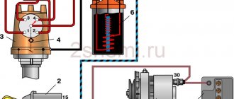
The design includes several components, each of which has its own nuances.
| Component | Peculiarities |
| Ignition coil | There are always two coils on a VAZ 2109. This mechanism is responsible for generating current |
| High voltage switches | Switch keys also work together. Through them, the current goes to the spark plugs, plus the controller regulates the time the current is turned on, which is calculated by receiving information from the crankshaft sensor |
| Electronic control unit | Responsible for distributing information in the form of electronic impulses |
| Frame | High-strength plastic is used for its manufacture, which largely ensures the durability and reliability of the device. |
Ignition coil
Location
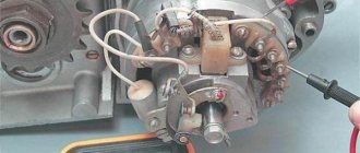
Any work related to repair, testing, and maintenance of the ignition module will be impossible to perform if you do not know basic things - the location of the device.
You can find the ignition module (ignition module) in the engine compartment. Find the high voltage wires that go to the spark plugs. One end is connected to them, and the other goes to the module. The MZ is small in size and enclosed in a plastic housing.
Device location
Principle of operation
Initially, on carburetor cars, the system worked due to the presence of an ignition coil. With injectors everything is somewhat different.
- Initially, the ignition coil is turned on, generating a high voltage current. The coil operates on the principle of magnetic induction;
- Then the electronic control unit MZ is connected to the work, performing the functions of control, transmitting commands, and ensuring the flow of current required by the characteristics to the spark plugs;
- Next, the spark plugs activate the spark, ignition occurs, and so on.
MH malfunctions
The ignition module often shows the most basic sign of failure - lack of spark. But this is not the only indicator of a malfunction. These also include:
- Lack of dynamics when accelerating the car. Trying to quickly pick up speed, you can clearly feel failures in engine operation;
- The engine does not produce the usual power; in some cases, the engine is not able to pull the car uphill;
- The idle speed fluctuates;
- One of the pairs of engine cylinders refuses to work. Here, most likely, there is no current that should come from the ignition coil.
To eliminate problems with the MH, the first thing you need to do is check the spark plugs, and then make sure the other elements are working.
Disconnect and check
Checking the spark plugs
To check the condition of the spark plugs, which may cause the module to malfunction, you need to:
- Unscrew the spark plugs from their seats, having first removed the high-voltage wires. The elements are removed with a special key.
- Inspect the spark plugs for carbon deposits, mechanical defects, and poor clearance.
- Send defective spark plugs to a landfill and install new ones in their place.
If replacing or cleaning the spark plugs does not produce results, then the reason lies in other elements of the ignition module.
Checking the Ministry of Health
To check the node, follow these steps:
- Check the condition of the high-voltage blocks going to the MH. If there are breaks or insulation failure, a spark will not form. Perform the check with a tester;
- The normal voltage on high-voltage wires is 12 Volts with a small permissible deviation;
- If the wires are OK, check the module. There are several ways to make this work;
- The first method is the simplest - replacing the old ignition module with a new one, the functionality of which you are sure of. But this is not an economical option, since MH is not the cheapest pleasure. Buying it for a simple test is not particularly wise;
- The second method involves the need to move the MH. While the engine is running, move the module and knock on it. If the motor starts to work differently, then there is simply no contact. The problem is not serious, since the module can be disassembled and all contacts secured, after which the MH will work like new;
- The third method is the most accurate, but also difficult. You will need a tester or ohmmeter. Measure the resistance on the high-voltage wires. Pay special attention to the data on the ignition module terminals between cylinders 2 and 3 and between cylinders 1 and 2. A resistance of about 5.4 kOhm is considered normal. If there are deviations, the MH must be replaced.
In practice, the ignition module on a VAZ 2109 rarely fails completely. Most often, the problem is a violation of the integrity of high-voltage wires or loss of contacts. But if you had to deal with a breakdown of the MZ, it’s not worth repairing it. It's better to replace it right away.
Monitor the condition of the wires and the gap on the spark plugs. A gap higher than normal leads to premature wear of the MH
interruptions in the operation of the engine of a VAZ 2108, VAZ 2109, VAZ 21099
During interruptions, the car engine idles unevenly, the engine does not develop sufficient power, and it consumes gasoline more. Engine failures on a VAZ 2108, VAZ 2109, VAZ 21099 are usually explained by incorrect carburetor adjustment, a faulty spark plug or one of the cylinders, or air leaks into one of the cylinders. It is necessary to find the fault and, if possible, eliminate it.
1. Start the engine of a VAZ 2108, VAZ 2109, VAZ 21099 car and leave the engine idling. Go to the exhaust pipe and listen to the sound of the exhaust. The sound should be even, “soft”, of the same tone. Popping sounds from the exhaust pipe at regular intervals indicate that one cylinder is not firing due to a failed spark plug, lack of spark at the plug, excessive air leakage into one cylinder, or a significant reduction in compression in the cylinder. Popping noises occur at irregular intervals due to improper carburetor adjustment, ignition, severe wear or dirty spark plugs. If popping noises occur at regular intervals, you can try to replace the entire set of spark plugs yourself, regardless of the mileage and appearance of the spark plugs, but it is better to do this after contacting a car service center to diagnose and adjust the carburetor and ignition system.
2. If the popping sounds are irregular, stop the engine and open the hood. Check the condition of the ignition system wires. High-voltage wires must not have insulation damage, and their tips must not be oxidized. If there is damage to the high-voltage wires, replace the faulty wire.
Other breakdowns
If the VAZ-2109 engine gets too hot, the problem lies in the unstable operation of one of the ignition or cooling systems.
Ignoring the situation will result in:
- formation of sediment on the piston rings;
- block head failure;
- deformation of the block head.
Any of the above breakdowns will result in expensive repairs.
Malfunctions that cause the engine temperature to increase:
- The coolant level in the expansion tank is too low - add coolant to the required level. Cold engine – MIN and MAX positions. If this doesn't help, look for a leak.
- The thermostat is broken - the only way out is to replace this part.
- There is an air lock in the cooling system. They often occur after replacing one of the elements: heater tap, heater, etc. Place the car on an inclined plane and let the engine run in this position. In 15 minutes all traffic jams will disappear.
- Low quality fuel with low octane number was used.
Other faults:
- engine wear - the piston rings wear out, which reduces compression, disrupting the combustion process of gasoline. Inexperienced car owners in such situations often begin to tune the engine to increase power, but only make it worse - the mechanism breaks down faster, working for wear;
- the car does not pull - the problem is related to the intermediate shaft;
- The engine does not run smoothly - the idle speed in the carburetor is poorly adjusted.
If your car stalls or does not start, this does not mean that the engine is broken; the essence may lie in other elements and mechanisms that are associated with it. Fuel your car only with high-quality gasoline and use the right oil, and the engine will last much longer even if it is not new.
The principle of operation of a four-stroke power plant
You can understand why it is important to connect high-voltage wires correctly if you study the principle of operation of the power plant. The carburetor or injector of the VAZ-2109 operates on approximately the same principle, since both power plants are four-stroke.
- First, the cylinder volume is filled with the fuel mixture and exhaust gases. This process is called "inlet".
- The engine then goes into compression. With it, the valves are closed, and the crankshaft and connecting rod move the piston upward. The mixture of fuel and air is transferred to the combustion chamber.
- During the expansion stage, the ignition is switched on and a spark appears. It ignites the fuel mixture, resulting in the formation of gases. They put pressure on the piston, causing it to move down. This force is transmitted through the connecting rod to the crankshaft.
- The process is completed by the “release” of exhaust gases through the exhaust system.
In order for the engine to operate smoothly and without jerking, the processes must take place in a certain order. This, first of all, concerns the order in which the cylinders are put into operation.
Finding the ignition moment in the ignition
On engine 402, ignition adjustment occurs according to the following algorithm and order:
- The crankshaft occupies a spatial position corresponding to 5 degrees of advance in ignition of the fuel mixture;
- This position can be easily achieved by aligning the mark on the pulley with the recess on the motor block;
- The coincidence means that the power plant has marked the end of a full piston stroke.
With the distribution sensor removed, adjustments are made as follows:
- I remove the spark plug from the head of the combustion chamber of the cylinder, which is listed as No. 1 in the order of fuel ignition;
- I cover it with a sheet of paper and turn the engine crankshaft;
- The air pushed out by the piston blows off the sheet, which indicates that it has reached the vertical maximum, from which the stroke begins;
- Then, using the keys, I set the octane corrector scale to 0.
Engine workflow through cylinders
The cylinders are activated as follows:
- In the first there is an upward movement. The gases expand and the mixture of air and fuel burns.
- In the third, to carry out the compression procedure, the piston rises.
- In the fourth, “injection” occurs - the piston moves down and at the same time a mixture of air and gasoline enters the cylinder.
- In the second cylinder, the piston rises and takes the upper position so that gases escape through the valve system. After which the exhaust gases are removed from the power unit.
Based on the principle of operation of the cylinders, their activation diagram looks like this: 1-3-4-2. It is important to connect them correctly so that the cylinders work in that order.
Cylinder head
Cylinder head 27 is common to four cylinders. cast from aluminum alloy, has wedge-shaped combustion chambers. Valve guides and seats made of cast iron are pressed into the head. The seats, pre-cooled in liquid nitrogen, are inserted into the sockets of the heated cylinder head. This ensures a reliable and durable fit of the seats in the head.
A special non-shrink gasket on a metal frame is installed between the head and the cylinder block. The head is centered on the cylinder block with two bushings and secured to it with ten bolts.
To uniformly compress the entire surface of the cylinder head gasket, to ensure a reliable seal and eliminate subsequent tightening of the bolts during vehicle maintenance, the cylinder head bolts are tightened evenly without jerking in four steps and in a strictly defined sequence (see Fig. 7):
- 1st step - tighten the bolts with a torque of 2 kg cm;
- Step 2 - tighten the bolts to a torque of 7.08-8.74 kg cm,
- Step 3 - turn the bolts 90°;
- Step 4 - turn the bolts again by 90°.
In the upper part of the cylinder head there are five supports for the journals of the camshaft 17. The supports are detachable. The upper half is located in bearing housings 16 and 21 (front and rear), and the lower half is in the cylinder head. The mounting bushings for the camshaft bearing housings are located at the housing mounting studs. The holes in the supports are machined together with the bearing housings, so they are not interchangeable, and the cylinder head can only be replaced assembled with the bearing housings.
A KLT-75TM type sealant is applied to the surfaces of the cylinder heads mating with the bearing housings in the area of the outer camshaft supports. Install the bearing housings and tighten the nuts securing them in two steps.
- 1st step - pre-tighten the nuts in the sequence indicated on sheet 7 until the surfaces of the bearing housings touch the cylinder head, making sure that the mounting bushings of the housings fit freely into their sockets;
- 2nd step - finally tighten the nuts to a torque of 2.2 kg/cm in the same sequence.
Valve distribution phases During one working cycle, four strokes occur in the engine cylinder - intake of the combustible mixture, compression, power stroke and exhaust gases. These strokes are carried out in two revolutions of the crankshaft, i.e. each stroke occurs in half a turn (180°) of the crankshaft.
The intake valve begins to open ahead of schedule, i.e. until the piston approaches top dead center (TDC) at a distance corresponding to 33* crankshaft rotation to TDC. This is necessary so that the valve is completely open when the piston goes down, and as much fresh combustible mixture as possible enters through the fully open inlet port.
How to connect wires correctly
When replacing high-voltage conductors, they are first connected to the ignition distributor. The distributor cover is convenient in that it is always installed in one position. There is a special mark on it, thanks to which it will not be difficult to place the part in place. Before connecting the wires, inspect the cover. It must be intact, since if cracks appear, the performance of this unit is not guaranteed.
The mark on the distributor cover is located next to the wire socket of the first cylinder. The firing order of the cylinders is slightly out of order (1-3-4-2) due to the ignition slider. It moves around the circle (distributor) counterclockwise. It is precisely by this principle of movement of the slider that it is easy to remember the order of the wires. They need to be connected to carburetor and injection VAZ-2109 according to the same principle. On the distributor cover, connect the wires according to the principle of movement of the slider, this is the only way you can set the ignition correctly:
- the socket of the first cylinder is located at the mark;
- the third one is connected at the very bottom;
- on the same line with the socket of the first, there is a place for the wire to the 4th cylinder;
- at the top point the second cylinder is connected.
Conclusion
The VAZ 2109 engine, or rather its varieties that were installed on the car, became legends of the Soviet automobile industry. So, having a fairly small size, it was powerful, which gave it great popularity among motorists. Another positive factor was that repairing the VAZ 2109 engine is quite easy to do with your own hands, which allows any car enthusiast to reduce costs at a car service center.
With the popularization of tuning, most drivers who owned 2109 engines began to carry out modifications and, as practice shows, quite successfully.
https://youtube.com/watch?v=5M7jgz9IVhI
Valve location
In the VAZ-2109 model, the designers changed the previously familiar system with a camshaft chain drive.
Despite the simplicity of the old design, it was noisy and required additional adjustments after a short period of time. In the nines, the shape of the upper part of the piston was changed, and special recesses were added for the valves.
An important adjustment task is also to align the camshaft and crankshaft on the same axis so that they rotate together.
The intake and exhaust valves are located in a certain order, this should be taken into account when adjusting
When adjustment is necessary
Valve adjustment is required when problems occur with the engine or after passing a technical inspection. Experienced car owners can quite accurately determine the cause of a power unit malfunction; the main signs are the following:
Valve adjustment is also required after every 25-30 thousand kilometers . During this time, some parts wear out and structural gaps increase. Diagnostics can be done at a service center; this service is inexpensive.
Preparatory work
From the adjustment tool you will need:
- set of wrenches;
- special device for adjustment;
- measuring probe;
- several adjusting washers;
- screwdriver;
- tweezers;
- valve cover gaskets.
Before starting the repair, set the car to the handbrake and engage any gear. One of the front wheels must be suspended so that the crankshaft can turn easily.
The procedure is as follows:
- Raise the hood.
- Disconnect all pipes from the cover.
- Remove the windshield wiper housing.
- We unscrew the spark plugs.
- Remove the front timing belt cover.
Tip: To monitor the current position of the piston, you need to use the viewing window.
For many VAZ models, the adjustment technology is not much different. Those who have already had experience of working with previous versions will find it easy to understand. The gaps are set according to the order in which the cylinders operate. The exhaust valves are 1, 4, 5 and 8 when counted from the camshaft drive belt. We use the following table in our work:
We use the table to correctly determine the cylinder number based on the crankshaft position
Tip: Before starting the adjustment, it is worth placing additional marks on the pulley every 90 degrees.
- Before adjustment, it is necessary to align the piston of the first cylinder. To do this, turn the crankshaft so that the marks on the pulley and the rear belt cover coincide.
The marks on the timing belt pulley and rear cover must be at the same level - Using a 17 key, turn the camshaft 3 teeth clockwise. This is necessary so that the camshaft cams move away from the pushers.
We install the camshaft so that the fists move away from the pushers - We test the gaps with an adjustment feeler; the tool should move under the influence of slight forces.
Using a feeler gauge, determine the amount of clearance on the first cylinder
If the gaps are increased or decreased, the following actions must be taken:
- We install the adjustment device on the bearing housing.
Installing the adjustment device - Turn the pusher towards you.
- Using the lever, we fix the pusher in the desired position.
We press the pusher using the lever and fix it in this position - Use long tweezers to remove the old washer.
Using tweezers, remove the old adjusting washer
The next task is to select a new washer of optimal thickness. Calculating this parameter is simple; we use the formula below:
- H = A + (B – C), where
- H – thickness of the new washer,
- A – thickness of the removed washer,
- B – gap size,
- C is the required gap.
Install a new washer and remove the retainer. We check the gap with a feeler gauge and, if necessary, select another washer of the required thickness. The finished set of washers contains products with a pitch of 0.05 mm. This procedure is carried out for each engine cylinder.
Features of modifications with an injector or carburetor
A considerable part of the owners of the VAZ-2109 model are equipped with an injector. When adjusting here, one important fact should be taken into account - thermal expansion.
When the engine is running, metal parts increase slightly in size, which leads to a decrease in clearances. Therefore, adjustments must be made only on a cold engine.
This way you can correctly measure the gap and select the adjusting washer.
How to set the ignition
In order to correctly adjust and set the ignition on a UAZ, you must follow the sequence of actions that are given in the user's repair manual.
Before you begin adjusting the ignition system, you must place the vehicle on an inspection pit or a special platform for repair work and apply the hand brake. The wheel mechanisms of the vehicle must be secured with a stopper or stop. The power unit must be turned off.
After this, you can begin installing the ignition. To do this, it is necessary to fix the piston of the first cylindrical element in the position of the highest dead center. In this case, you need to check that the hole on the crankshaft pulley coincides with the pin on the cover of the timing gear block. It is necessary to slightly lower the mounting bolt located on the plate to the distribution equipment sensor housing.
Then remove the cover from the distributor and rotate the crankshaft 180°. The octane corrector must be in the zero position. Then it is necessary to tighten the pointer to the housing of the distribution mechanism sensor with a bolt so that its position coincides with the octane corrector mark.
After this, we adjust the slider by rotating it counterclockwise. This will help eliminate gaps in the drive. When the tip on the stator coincides with the red mark, you can fix the plate with a bolt.
Then you need to replace the switchgear sensor cover and check that the ignition leads are installed correctly according to the operating order of the cylindrical mechanisms (1-2-4-3). You need to count in a counterclockwise direction. The ignition setup on the UAZ is completed.
Now it is recommended to start the power unit and warm it up to operating temperature (about +80°C). Then you need to sharply press the accelerator at a speed of 40 km/h on a straight section of the road.
In case of severe detonation, it is recommended to turn the distributor sensor 0.5-1 turn on the octane corrector scale in a counterclockwise direction.
If there is no detonation, you need to increase the advance angle by turning the sensor clockwise.
The procedure for connecting high-voltage wires VAZ
First, let's decide which of the four cylinders is first?
The first cylinder in front-wheel drive VAZs is located closer to the timing belt. If you look at the engine from the front, the first cylinder is the leftmost). And then everything is simple - from left to right - 1, 2, 3, 4.
In rear-wheel drive VAZ Classic and Niva, the first cylinder is located closer to the front bumper of the car.
General tips for connecting high-voltage wires
Checking high-voltage wires. To check the wires, you will need a multimeter tester. Check the resistance of the wires - it should be no more than 20 KOhms (in practice, the longest wire of cylinder 1 has a resistance of up to 10 KOhms).
If the wire resistance is more than 20 Kom, it must be replaced. Carefully inspect the wires for chafing on parts of the motor or other wires. In case of significant abrasion, replace the wire.
In case of minor abrasion, it is possible to lay the wire so that it does not rub and fix it in this position.
Laying wires. Do not try to connect the wires in a bundle. Disassemble the wiring harnesses, release the wires from the plastic holders. Connect the high-voltage leads to the corresponding cylinder spark plugs.
Lay the wires so that they do not rub against each other, engine parts, or hoses. Avoid sharp bends and tension on the wires.
After connecting all the wires, secure them into the bundle with special comb holders included in the delivery kit.
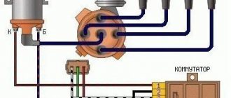
The procedure for connecting I/O wires to a VAZ carburetor (2108, 2109, 21099)
- The central wire from the distributor cover always goes to the ignition coil (bobbin).
- The outlet of the distributor cover, which faces towards the front of the car, is connected to the first cylinder.
- The outlet of the distributor cap, looking down, is connected to the third cylinder.
- The outlet of the distributor cap, looking rearward, is connected to the fourth cylinder.
- The outlet of the distributor cap, looking up, is connected to the second cylinder.
- The procedure for connecting high-voltage wires to a VAZ Classic, Niva with a carburetor and distributor.
Central wire from the ignition coil (bobbin)
1 cylinder - above the vacuum corrector. Next, clockwise, the order is 1-3-4-2.
Injection VAZ produced before 2004 with an old-style ignition module (4-pin low-voltage connector)
Actually, on the module body it is already indicated which cylinder the pins correspond to - but we duplicated them in red in case the module gets completely dirty, and you might not be able to see it in the photo.
Injection VAZ produced after 2004 with a new ignition coil (3-pin low-voltage connector)
As with the old-style ignition modules, the new coils are also marked with pins corresponding to the cylinders. But the connection order is different from the order on the old-style ignition module. Be careful.
Cylinder block
All engine cylinders are combined together with the upper part of the crankcase into one common unit - a cylinder block cast from special high-strength cast iron. This arrangement ensures structural strength, rigidity, compactness and reduces engine weight. Coolant passages are made along the entire height of the cylinder block, which improves cooling of the pistons and piston rings and reduces deformation of the cylinder block from uneven heating.
The block cylinders are divided into five classes by diameter at 0.01 mm intervals. designated by the letters A, B, C, D, E:
| Class | Engine cylinder diameter 21081, 2108, mm | Engine cylinder diameter 21083, mm |
| A | 76,000-76,010 | 82,000-82,010 |
| IN | 76,010-76,020 | 82,010-82,020 |
| WITH | 76,020-76.030 | 82,020-82,030 |
| D | 76,030-76,040 | 82,030-82,040 |
| E | 76,040-76,050 | 82,040-82,050 |
The cylinder class is indicated on the bottom plane of the block opposite each cylinder. The cylinder and the piston mating to it must be of the same class. During repairs, the cylinders can be bored and honed to accommodate an increased piston diameter of 0.4 and 0.8 mm.
At the bottom of the cylinder block there are five crankshaft main bearing supports with thin-walled steel-aluminum liners. The upper and lower liners of the middle (3rd) main bearing are without a groove on the inner surface. The remaining supports have upper liners with a groove on the inner surface, and lower ones without a groove. Until 1988, the lower shells of these bearings also had grooves.
The bearings have removable covers 2, which are attached to the cylinder block with self-locking bolts. The holes for the crankshaft bearings in the cylinder block are processed together with covers, which ensures high accuracy, the correct geometric shape of the holes and their alignment. Therefore, the bearing caps are not interchangeable and, to distinguish them, have marks on the outer surface (see Fig. 6).
The procedure for connecting high-voltage wires on a VAZ 2109 (carburetor, injector)
The ignition module on injection VAZ 2109 is deservedly considered one of the most complex electrical components. If the injectors have a module, then the carburetors have the simplest coil.
The actual, but incredibly important task of the module is the generation of high voltage current, which can reach 30 thousand watts. The current follows high-voltage wires to the spark plugs, which create a spark to ignite the air-fuel mixture.
The classic ignition coil is one of the components of the module, so the system works on a much more complex principle than on carburetors.
High voltage wires
Often, the main difficulty when repairing a carburetor VAZ 2109 is the reconnection of high-voltage wires that were previously disconnected from the distributor cover. It's also an ignition distributor.
The difficulty is that many people forget the connection procedure or simply do not know. But in practice, returning high-voltage wires is much easier than understanding the ignition module used on the injection VAZ 2109.
By following a few simple rules, you can easily return the wires to their rightful places.
- The ignition distributor cover is installed in its place, that is, on the distributor, only in a single position. Therefore, even if you wanted to, you won’t be able to confuse anything here. Otherwise the lid simply won't fit.
- There is an installation mark on the cover, which indicates the location of the wire socket from the first cylinder.
- The wires must be connected in the following sequence - 1, 3, 4, 2. Move counterclockwise when looking at the distributor cover from the side of the expansion tank.
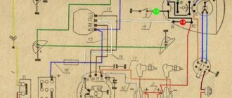
If for some reason there are no installation marks on the VAZ 2109 carburetor distributor cover, just follow the connection principle shown in the image.
Causes
VAZ 2109 ignition system, device, principle of operation
There are several most common reasons why a car owner has to remove the engine from his car.
| Cause | Peculiarities |
| Major renovation | In the event of a serious accident or as a result of wear of key engine elements, it will not be possible to restore its functionality without a removal procedure. Therefore, they resort to dismantling the engine |
| Replacement | It’s not uncommon for VAZ 2109 owners to think about replacing the standard factory engine with a more efficient, powerful power unit. This is a serious step, where dismantling is one of the initial stages |
| Finalization | If there is no opportunity or desire to change the engine, some simply modify the existing one. Tuning can be quite complex, involving the need to completely remove the engine from the engine compartment |
Regardless of the reasons, you need to remove the engine carefully, following a clear sequence of your actions. Decide in advance whether you will dismantle the engine together with the gearbox or without removing it.
Block head and timing device
All front-wheel drive cars of the VAZ family, be it 2109, 2110 or 2114, have one cylinder head, common to all cylinders. They are mounted to the block using ten screws. During installation, a metal gasket is placed under it. This gasket is for single use and cannot be reused. There are five camshaft bearings at the top of the cylinder head.
The camshaft of the engine of the VAZ-2109 car has the index 21083. Some engines are equipped with 2110 or 2111 shafts; their design is slightly different from 21083, which allows for an increase in engine power. The shaft is cast from cast iron, there are five supports and eight cams on it that open the valves. It is driven by a toothed belt from the crankshaft pulley. The shafts can be correctly installed relative to each other using the alignment lug on the rear timing belt cover and the marks on the drive gears and flywheel.
Seats are pressed into the cylinder head, as well as valve guides. On the inside of the bushings there are grooves for supplying lubricant; the bushings are closed on top with oil deflector caps.
The valves are made of steel, and the intake head is made of heat-resistant steel. They are mounted obliquely in one row. The inlet valve has a larger diameter than the outlet valve. The gaps between the valves and camshaft cams are adjusted using shims that have increased wear resistance.
Pushers are metal cups moving in the cylinder head holes. To improve wear resistance, the surface in contact with the ends of the valve stems is cemented.
Engine crank mechanism
The design of the cylinder block of the VAZ-2111 engine is identical to block 21083. It is cast from cast iron, the cylinder diameter is 82 mm, and if the piston group is replaced, it can be increased by:
Crankshaft
The crankshaft is located at the bottom of the block and rotates on five main bearings that have removable covers, which are secured to the block with bolts. The covers are not interchangeable and are marked with marks on the outside. The middle support of the main bearing has slots into which support half-rings are installed, eliminating axial displacement of the crankshaft. The front half-ring is made of an alloy of steel and aluminum, the rear half-ring is made of cermet. If play in the crankshaft appears, the half rings must be replaced.
The bearing shells - support and connecting rod - are thin-walled, made of steel-aluminum alloy. There are grooves on the inside of all the upper main bearings, with the exception of the third bearing bearing.
The design of the crank (engine crankshaft) is as follows: it is cast iron, has four connecting rods and five main journals. Eight counterweights are cast together with the shaft. Channels are drilled inside the shaft, closed with plugs and having a dual purpose:
- they supply oil to the connecting rod journals from the main ones;
- they clean the oil, since centrifugal force throws all mechanical impurities that are not retained by the filter towards the plugs.
Video “The principle of operation of internal combustion engines”
This instructional video explains how the combustion system works.
Everything about engines 2108, 21083, 21081 Two articles by S. Geraskin, published in the magazine “Behind the wheel” in 1995 about engines 1100, 1300 and 1500 cm for front-wheel drive Samara. Placed without remarks or significant abbreviations. Twins are brothers. Behind the wheel. N 3 1995
For 10 years now, the VAZ-2108 has been produced in Tolyatti, and models -21083 and -21081 have been produced a little less. The time has come to “declassify” the history of their appearance and talk about the design features - especially since we have more and more re-exported “eighty-first” ones. Word from VAZ specialist S. GERASKIN. At the end of the distant 70s, a decision was made to create a new (after the Zhiguli) family of VAZ cars. The Office of the Chief Designer developed a technical specification (TOR), having analyzed foreign samples (Mazda-323, Volkswagen Golf, Citroen Visa, etc.). This is what the designers determined: the car must have front-wheel drive and a “swinging candle” suspension. engine with a displacement of 1300 cm*3 smaller in size compared to the existing one, drag coefficient (Cx) below 0.4. Since all the ideas accepted for implementation were new for VAZ, they decided to bring him in as a consultant. The base (and only) model of the contract was the VAZ-2108 with a 1300 cm*3 engine and a five-speed gearbox. At that time, the plant did not receive money from the ministry to develop other modifications. But they (not money, but modifications) were in the plans. About a year later, VAZ started working on the -21083 (1500 cm) engine, and after about six months - 21081 (1100 cm). Why did the 1300 cm3 engine become the base engine? From layout calculations and analysis of the automotive market, it was concluded that for a car of this class, weight, and purpose, a power of 60-62 hp would be sufficient. With. From here we calculated the displacement of the engine. Then they developed the -21083 motor. using the same cylinder block. This engine was born with difficulty, because almost nothing could be changed: the distance between the axes of the cylinders was set by the dimensions of the block, the materials were the same, etc. In other words, it was necessary to make candy from scrap material. And problems. inherent only to this engine were enough: unable to withstand the loads, the block cracked: the piston lifted and the piston pin jammed due to thermal stress (after all, there are no passages between the cylinders for coolant). And a whole bunch more: pitting on the liners and cracking of the exhaust manifold, pushing through the mating plane of the head and crushing the bosses. But during the fine-tuning process, the engine was brought up to the required reliability, although the power characteristics had to be reduced. However, the engine remained the most sensitive to the slightest deviations from documentation requirements, be it the quality of materials or the processing of parts. The power of a one and a half liter engine is approximately 6 liters. With. more. But it mainly determines the maximum speed. For acceleration and ease of maneuver, another indicator is much more important - maximum torque. This is where the 1500 engine gives a noticeable advantage. True, there was a fly in the ointment: the maximum torque corresponds to too high speeds. The current head of the STC engine development department, P. Byvshev, once argued that the engine should produce such a torque at 2500 rpm. Then, by selecting the gear ratios of the gearbox, it would be possible to achieve all the technical specifications for this car, while simultaneously significantly reducing fuel consumption, noise and toxicity. Now this option is implemented on an engine with injection. Engine -21081 has a completely different story. It was included in the range of engines being developed at the request of the export department, since in many countries (Belgium, Greece, Portugal) the tax on a car is determined by the displacement of its engine. In other countries, these cars attract customers with a low contract price. They come to us “from there” - the plant did not supply them to the domestic market. A car with this engine behaves rather sluggishly: besides. in order to meet toxicity standards in Europe, it had to be “tightened” by regulation. But. Let's say, for older people who buy cars solely based on the price-interior volume ratio, it provides certain advantages. And yet the engine was not in great demand. The “1100” engine is not particularly convenient for production: there are quite a few differences from the base engine (more on them below). At the same time, it turned out to be the least loaded and therefore “forgiving” even significant deviations in material and manufacturing. That's the story. And now about that. what was changed in the modifications of the -2108 engine. In the -21081 engine, the piston stroke is reduced and, as a result, the displacement is reduced. The cylinder block is 5.6 mm lower: the other dimensions have not changed, and there is nothing new in the repair technology. Crankshaft: the distance between the axes of the connecting rod and main journals has been reduced by 5.2 mm. The location of the lubrication holes on the connecting rod journals will help you “calculate” the shaft - on shafts -2108 and -21081 they are offset from the axis of the journal in opposite directions. The cylinder head is the same. By the way. if you bought a new head for your V8 and found the marking “21081” on it. don’t be upset - this is how it should be, this part is considered “native” for two engines. The only difference is the location of the pin for the timing belt tension roller. There are two threaded holes in the head and, depending on the type of engine - 1.1 or 1.3 liters - one or the other is used for the stud. The transfer of the tension roller made it possible to use the same toothed belt on engines with different center distances of the camshaft and crankshaft pulleys. The camshaft is original, with a different cam arrangement, which is associated with a change in valve timing on an engine with a “low” block. The carburetor model -21081 differs in calibration parameters - the cross-section of the fuel jets and starting clearances. The chain is identical to the “eight”, the methods of its adjustments are identical. disassembly and assembly remained the same. The exhaust system does not have the usual “pants” - the exhaust pipe is single, and the exhaust manifold is made with one outlet. Accordingly, a bracket and a clamp for fastening to the block are made for the exhaust pipe. A distributor sensor with different characteristics of centrifugal and vacuum ignition timing regulators is installed in the ignition system. Externally, this device can be recognized by the red mark on the cover of the vacuum regulator. The initial ignition timing has changed, which must be remembered when adjusting. One scale division in the clutch housing hatch corresponds to 1 degree of crankshaft rotation. therefore, in the strobe beam, the mark on the flywheel should be 5-6 divisions short of the middle mark of the scale. Let us remind you that on the -2108 engine the mark does not reach the middle of the scale by one division. Here. perhaps all the differences between the engine are -21081. Let's now look at the one and a half liter engine -21083. Here the designers took a different path, namely: they achieved a larger working volume than at -2108. increasing the diameter of the cylinders. It's clear. that there were differences in the design and repair of the cylinder block, pistons, cylinder head and carburetor. The design of the block is the same, only the dimensions (including repair ones!) of the cylinders and... the color have changed. The “eighty-third” block is easy to recognize - its pleasant blue color distinguishes it from its gray “brothers”. The pistons have increased in diameter and acquired grooves on the bottom, which will prevent the valves from hitting the piston if the timing belt breaks. A large piston requires large piston rings and other pins (from the VAZ-2101) - do not forget this when purchasing spare parts! In the cylinder head, the diameters of the intake valves (from 35 to 37 mm), seats and intake ports have been increased. Head gasket - with increased diameters of holes for cylinders. The design of the carburetor has not changed, but the flow sections and calibration data, including starting clearances, have changed. In the ignition system, all instruments remain the same (unless a microprocessor engine control system with two ignition coils and other tricks is used). The new initial ignition timing requires a slight adjustment of the actions when adjusting with a strobe light: the mark on the flywheel should not reach the middle division of the scale in the clutch housing hatch by 3-5 divisions (why - see above). The rest of the engine parts are “figure eight”, we won’t dwell on them; and if you are overcome by doubts when choosing spare parts, pay attention to their markings - the first few numbers indicate the engine model. We hope this article will help you in your choice. both in the maintenance and repair of the Samara, and at car wreckers - in search of the necessary spare parts. “1500” versus “1300” Driving N 7 1995 In the third issue of the magazine for this year, in the article “Twin Brothers,” VAZ specialist S. GERASKIN spoke about the features of the VAZ-2108 engine family with a volume of 1100, 1300 and 1500 cm*3. Today he continues this theme. In the previous material, I touched on the history of the creation of the VAZ-21083 engine (1500 cm). Some readers have made the incorrect conclusion that this engine is less reliable than the 1300 and 1100. In fact, this is not the case, although the one and a half liter engine requires proven and stable production technology and more attention during maintenance and repair. I'll try to explain why. First, I will note that the engines of the VAZ-2108 family are said to be an order of magnitude better than any other engines of domestic passenger cars. This statement is based on an analysis of their design and characteristics. Of course, our engines have passed the entire cycle of necessary tests (stipulated by GOSTs and VAZ factory methods). And the design of the engines and all parts meets the requirements laid down in the technical specifications and regulatory documents. But production-technological, supply-political and other reasons often appear that violate compliance with these requirements. Such changes can be called emotional deviations. Continuous, mass production (at VAZ it is still preserved) requires a rhythmic supply of components, raw materials, materials. It’s very difficult to keep the rhythm, especially in today’s Russia. That’s why other “innovators” try to manufacture parts from materials that do not correspond to the drawings. Although the reasons for such deviations can be very diverse - reduction in energy intensity, labor costs, time, etc. The disenfranchised domestic car enthusiast cannot fight this. Although he feels that the engine (car) is not behaving in the best way. And for the plant there are such miscalculations that a pellet is for an elephant - it’s big, it won’t last. Then the emotional terms “less” or “more” acquire material embodiment. More about this. Cylinder block. In the previous article, we said that the cylinder blocks of the -21083 and -2108 engines are identical in overall dimensions and distances between the cylinder axes (89 mm). The cylinder diameter of the VAZ-21083 engine is 82 mm, VAZ-21 08 is 76 mm. The thickness of the cylinder walls according to calculations (drawings) is at least 4.5 mm. And it is clear to a non-specialist that it is advisable to wash the cylinders with coolant from all sides: heat is better removed, temperature deformations are more uniform, and stresses are less. And hence all the derivatives - greater reliability and durability, less demands on deviations from the drawings. The last factor is significant for Russian conditions. In the VAZ-2108 block (1300 cm), the thickness of the jumper between the cylinders is 13 mm (89-76-13). The width of the water channel (duct) between them is 4 mm, respectively. The VAZ-21083 (1500 cm) has a jumper of only 7 mm (89-82-7). Therefore, there are no flows between the cylinders (in the plane of the cylinder axes) - the walls here are not washed by the coolant. With this design, the temperature regime of the block and cylinder-piston group of the VAZ-21083 engine is, of course, more intense than the VAZ-2108. And this requires mandatory compliance with strict manufacturing conditions for pistons, rings and fingers. The increased thermal stress of the block in a one and a half liter engine will quickly reveal any deviations from the specified dimensions of these parts moving in the cylinder. And of course, it will not forgive other production flaws: casting sand not completely knocked out of the block, burrs or nicks on the piston due to careless transportation, displacement of the piston pin, underestimated diameter of the piston skirt. All this, I repeat, will accelerate engine failure. The same cannot be said about the VAZ-2108 engine - with such deviations it can easily work out its service life of 125,000 kilometers. And further. The cylinders of the VAZ-2108 engines are connected at the top by a fairly powerful “plate” 12 mm thick. When the cylinder head is tightened, the cylinders “bend” and the plate transmits force from one cylinder to another, preventing each individual from clearly maintaining a cylindrical shape. That is why a one and a half liter engine requires parts only “tolerance”, precise technology for their processing and assembly. By the way, athletes remove these connections between the cylinders (“unravel” the plate) and thereby prevent possible defects. Cylinder head and gasket. It is very important to use an alloy of a precisely defined composition for the head. The fact is that a little recycled aluminum is added to it. If there is more of it than permissible, the stiffness of the head is greatly reduced. During the manufacturing process, this must be monitored especially strictly. During the development of the one and a half liter engine, to increase the safety margin (protection in case of deviations in material and technology), the configuration of the head bosses for its fastening screws was changed. This shape does not allow the bosses to crack even with serious deviations (for the worse, of course) in the structure of the material. The open arch of the combustion chamber of the -21083 head is larger than that of the -2108, and therefore it perceives greater force from the gases. If the addition of secondary aluminum in the head exceeds the norm, then after 60-90 thousand kilometers the joint between the head and the cylinders will certainly open - as a rule, in the narrowest (where there are no passages for water) and heat-stressed place, between the second and third cylinders. And then everything will go according to the standard pattern: curvature of the mating plane of the head, burnout of the gasket, rapid wear or destruction of seats and valve guides. The gasket is a thin part. Its task is not only to seal the joint between the head and the block, but also to compensate for thermal deformations that occur in the connection during engine operation. Since they are more pronounced in a one and a half liter engine, the requirements for the gasket (material, size, workmanship) are more stringent than for the 1300 engine. Therefore, never use a used gasket, and when buying a new one, take a close look at it. If you have doubts about the quality, don’t buy it. At the Yegoryevsky plant, where they make gaskets for VAZ-2108 engines, they sometimes allow deviations from the requirements of the drawing. I note that the position of the spark plug in the head of the VAZ-21083 has not changed. Due to the larger cylinder diameter, the flame front takes longer to reach the outermost places of the combustion chamber. Therefore, the resistance to detonation in the -21083 engine is lower than in the -2108. If the driver does not listen to the engine, uses gasoline with a low octane number and drives with detonation, a one and a half liter engine is not for him. In conclusion, I will repeat once again that VAZ-2108 (-21083) engines are reliable and durable, superior to other domestic and even some foreign analogues when everything is done properly. But if there are deviations from the drawings, the 1300 engine has a much greater chance of survival than the 1500.